

Page 1

INSTRUCTION MANUAL
MANUAL DE INSTRUCCIONES
Model Numbers/ No. de Modelos:
AIR CONDITIONER
AIRE ACONDICIONADO
CAUTION:
BEFORE USE, PLEASE READ AND FOLLOW ALL SAFETY RULES AND OPERATING
INSTRUCTIONS.
La sección en español empieza en la página 17.
Avanti has a policy of continuous improvement on its products and reserves the right to change materials and specifications
without notice.
Avanti Products, A Division of the Mackle Co., Inc.
P.O. Box 520604 - Miami, Florida 33152
www.avantiproducts.com
Page 2

2
REGISTRATION INFORMATION
Thank you for purchasing this fine Avanti product. Please fill out this card and return it within 100
days of purchase and receive these
important benefits:
? Protect your product:
We will keep the model number and date of purchase of your new Avanti product on file to
help you refer to this information in the event of an insurance claim such as fire or theft.
? Promote better products:
We value your input. Your responses will help us develop products designed to best meet
your future needs.
-------------------------------------------------(detach here)----------------------------------------------------------
Avanti Registration Card
__________________________________ _____________________________________
Name Model # Serial #
__________________________________ _____________________________________
Address Date Purchased Store/Dealer Name
__________________________________ ______________________________________
City State Zip Occupation
__________________________________ As Your Primary Residence, Do You:
Area Code Phone Number ?Own ?Rent
Did You Purchase An Additional Warranty: Your Age:
?Extended ?None ?under 18 ?18-25 ?26-30
Reason For Choosing This Avanti Product: ?31-35 ?36-50 ?over 50
Please indicate the most important factors Marital Status:
that influenced your decision to purchase ?Married ?Single
this product. Is This Product Used In The:
?Price ?Home ?Business
?Product Features How Did You Learn About This Product:
?Avanti Reputation ?Advertising
?Product Quality ?In Store Demo ?Personal Demo
?Salesperson Recommendation ?Other______________________________
?Friend/Relative Recommendation Comments____________________________
?Warranty _____________________________________
?Other_______________________ _____________________________________
Page 3

3
Page 4

4
HELP US HELP YOU...
Read this guide carefully.
It is intended to help you operate and maintain
your new air conditioner properly.
Keep it handy to answer your questions.
If you don't understand something or you need
more assistance, please call:
Avanti Customer Service
800-220-5570
Keep proof of original purchase date (such as
your sales slip) with this guide t o establish the
warranty period.
IF YOU NEED SERVICE
We're proud of our service and want you to be
pleased. If for some reason you are not happy
with the service you receive, here are some
steps to follow for assistance.
FIRST, contact the people who serviced your
air conditioner. Explain why you are not
pleased. In most cases, this will solve the
problem.
Write down the model and serial numbers.
You'll find them on the rating plate located on
the right side of the unit.
Please write these numbers here:
____________________________________
Date of Purchase
____________________________________
Model Number
____________________________________
Serial Number
Use these numbers in any correspondence or
service calls concerning your air conditioner.
If you received a damaged air conditioner,
immediately contact the dealer (or builder) that
sold you the air conditioner.
Save time and money. Before you call for
service, check the Troubleshooting Guide. It
lists causes of minor operating problems that
you can correct yourself.
NEXT, if you are still not pleased, write all the
details, including your telephone number, and
send it to:
Customer Service
Avanti Products
10880 NW 30 Street
Miami, FL 33172 USA
Page 5

5
PARTS AND FEATURES
1. INTERIOR AIR INLET GRILLE
2. FRONT PANEL
3. CABINET
4. AIR FILTER
5. INTERIOR AIR OUTLET
6. EXTERIOR AIR INLET
7. POWER SUPPLY CORD
8. FRESH AIR VENT LEVER
9. CONTROL PANEL
10. AUTO SWING SWITCH
Page 6

6
TABLE OF CONTENTS
Registration Information ________________________________ ______________________________2
Help Us Help You_______________ ___________________________________________ ______4
Parts And Features_______________________________________________________________5
Important Safety Instructions __________________________________________________________7
Tips Before Installing Your Air Conditioner______________________________________________7
Tools Needed For Window Installation___________________________________________ ____7
Installation Instructions _______________________________________________________________8
Select The Best Location________________________________ ______________________________8
Window Installation Steps _____________________________________________________________9
Installation of Mounting Brackets 9
Installation Of The Cabinet________________________________________________________10
Electrical Connection___________________________________________________________ _11
Operating Your Air Conditioner _______________________________________________________10
Care And Maintenance_______________________________________________________________11
Cleaning The Air Filter _______________________________________________________________13
End-Of-Season Care_________________________________________________________________ 13
Troubleshooting Guide ______________________________________________________________14
Service For Your Air Conditioner______________________________________________________15
Your Avanti Products Warranty _______________________________________________________16
Wiring Diagram ________________________________ _____________________________________17
Instrucciones En Español _________________________________________________________ 18-24
Page 7

7
IMPORTANT SAFETY INSTRUCTIONS
?ELECTRIC SHOCK HAZARD?
? Read all instructions before using the air conditioner.
? If the air conditioner has a serial plate rating of 115 Volts ~ AC and up to and
including 7.5 amps the unit may be on a fuse or circuit breaker with other devices.
However, the maximum amps of all devices on that fuse or circuit breaker cannot
exceed the amps or the fuse of circuit breaker.
? If the air conditioner has a serial plate rating of 115 Volts ~ AC and greater than 7.5
amps it must have its own fuse or circuit breaker, and no other device or unit should
be operated on the fuse or circuit breaker.
? To avoid the possibility of personal injury, disconnect power to the unit before
installing or servicing.
-Save these instructions-
Tips Before Installing Your Air Conditioner
? Your room air conditioner unit is designed to be highly efficient and save energy. Follow these
recommendations for greater efficiency.
? Select thermostat setting that suits your comfort needs and leave the thermostat at that chosen
setting.
? The filter is very efficient in removing airborne particles. Keep air filter clean. The, filter should be
cleaned once a month. More frequent cleaning may be necessary depending on outdoor and
indoor air quality.
? Use drapes, curtains, or shades to keep direct sunlight from heating your room, but DO NOT
obstruct the air conditioner. Allow air to circulate around the unit without obstructions.
? Start your air conditioner before the room temperature air becomes hot and uncomfortable. This
avoids an initial period of discomfort while the unit is cooling off the room.
? When room temperature is cool enough, use HIGH or LOW FAN only. This circulates the air,
providing some cooling comfort, and utilizes less electricity than when operating on a cooling
setting.
? Save the shipping carton and packing materials for future storage or transport of the unit. Please
check the contents of hardware kit against the corresponding model check list, prior to installation
of the unit.
? Before Starting The Unit:
? Select a suitable location with easy access to an electrical outlet.
? Leave at least 12” of space between your unit and the nearest object, including the wall.
? Install the flexible exhaust hose and the adjustable window slider kit provided (see figure ).
? Plug unit into a 115v/60Hz grounded electrical outlet.
NOTE: Use drapes, curtains or shades to keep direct sunshine from penetrating the room but do not
allow them to obstruct the air flow around the unit.
To reduce the risk of fire, electrical shock,
or injury when using your air conditioner,
follow these basic precautions:
Page 8
8
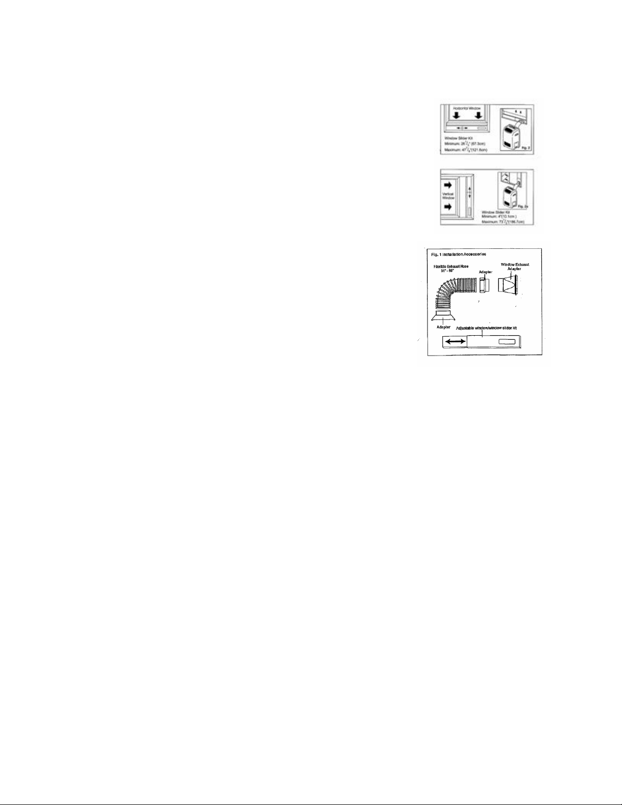
WINDOW KIT INSTALLATION
Installation Accessories (See Fig 1)
Flexible exhaust hose with adapters - 3 pieces
Window exhaust adapter - 1 piece
Adjustable window slider kit – 1 piece
Window KIT Installation:
Kit provided has been designed to fit most standard v ertical and horizontal
window applications.
Please refer to figures 2A & 2B for minimum and maximum window openings.
For certain type of windows you may have to modify the window slider kit.
Exhaust/Window Kit
The exhaust/window kit must be installed at all times when the unit
is operating under the cooling mode. There should be at least 11.8””
(30 cm) clearance between the unit and any other objects or building
structure. The unit should be installed on a level surface. The
window kit does not have to be installed during operation of the
remaining two modes. (Dehumidifying/ Fan).
INSTALLATION INSTRUCTIONS
Installation Accessories
Flexible exhaust hose
Minimum: 21.6” (55 cm)
Maximum: 59” (150 cm)
The unit operates more efficiently if the exhaust hose is shorter.
The exhaust/window kit must be installed at all times when the unit is operating under the cooling
mode.
Page 9

9
?
Warning
?
Electrical Connection
Improper use of the grounded plug can result in the risk of electrical shock. If the power cord is
damaged, have it replaced by an authorized Avanti Products service center.
All wiring must comply with local and national electrical codes and must be installed by a qualifi ed
electrician.
Check available power supply and resolve any wiring problems BEFORE installing and operating this
unit.
This air conditioner should be properly grounded for your safety. The power cord of this air
conditioner is equipped with a three-prong plug which mates with standard three prong wall outlets to
minimize the possibility of electrical shock. If you are not sure whether your wall outlet is properly
grounded, please consult a qualified electrician.
Do not under any circumstances cut or remove the third ground prong from the power cord supplied.
This air conditioner requires a standard 115/120 Volt~AC/60Hz electrical outlet with three -prong
ground.
Never unplug the air conditioner by pulling the power cord. Always grip the plug firmly and pull
straight out from the receptacle.
Do not use plug adapters or an extension cord with this appliance. If the power cord is too short, have
a qualified electrician or service technician install an outlet near the appliance.
Page 10

10
OPERATING YOUR AIR CONDITIONER
Control Panel Key Pad
TEMPERATURE
Press up and down keys to select a suitable temperature
setting. The temperature selected will be displayed in the
LCD window. Temperature settings are adjustable between
15ºC (58 ºF) to 31 ºC (90ºF).
SPEED
Press speed key and the speed sequence will be displayed
in the LCD window.
(LOW – MED - HIGH)
MODE
Each pressing of the mode key will advance to a different
mode setting.
(AUTO – COOL – FAN – HUMIDIFY – HEATING)
The running mode selected w ill be displayed in the LCD
window.
TIMER ON/OFF
Press this key to set desired auto -timer settings sequences
of 30 minutes, from ½ hour to 12 hours.
Every time you press the “TIMER” key, the “AUTO OFF”
time will be displayed in the LCD window.
The same applies to “AUTO ON” time.
ON/OFF
To turn power on, press ON/OFF key once. The unit will
run at auto mode. LCD window will display “AUTO”.
Page 11

11
AUTO Display
When this sequence is selected after pressing the MODE
button, the corresponding signal indiactor is lit.
In this mode, your unit will logically choose a desired
room temperature. If the temperature is not comfortable
for you, the desired MODE can be select manually.
FAN Display
When this sequence is selected the corresponding signal
indicator is lit, after pressing the mode button.
TEMPERATURE Display
When these buttons are pressed, the corresponding area
will show the selected temperature.
COOL Display
When this sequence is selected, after pressing the MODE
button, the signal indicator is lit. Then push the
temperature buttons to set the desired room temp.
HUMIDIFIER Display
When this sequence is selected after pressing the mode
button, the corresponding signal indicator is lit.
Under this mode, you cannot select a fan speed or adjust
the temperature since the fan motor operates at a pre -set
fan speed.
Page 12

12
REMOTE CONTROL OPERATION
The remote control uses 2 alkaline dry batteries (AAA 1.5V).
To install the batteries, slide back the cover and mount them according to the (+ and -) signs shown
on the rear compartment.
NOTE:
If you plan not to use the control for several weeks, remove the batteries.
When replacing the batteries, do not mix old and new.
Replace the batteries when the transmission indicator light fails to appear.
ON/O FF Button:
Press ON/OFF button when the portable air conditioner is ready for use.
The unit is ready to be programmed in auto mode.
The LCD window will display “AUTO”.
MODE Button:
Push the “MODE” button. Each time you press the button, a mode is selected in a sequence that goes
form AUTO – COOL – FAN – HUMIDIFIER - HEATING
Page 13

13
CARE AND MAINTENANCE
? When servicing the air conditioner, be sure to turn the operation switch to the “OFF” position and
disconnect the power cord from the electrical outlet.
? Do not use gasoline, benzine, thinner or other chemicals on the air conditioner as these
substances may cause damage to the paint finish and deformation of plastic parts.
? Never attempt to pour water directly to the front of the unit as this will cause deterioration of the
electrical insulation.
Cleaning the Air Filter
If the air filter becomes clogged with dust, airflow is obstructed and reduces efficiency. The air filter
should be cleaned once a month. More frequent cleaning may be necessary depending on outdoor
and indoor air quality.
The air filter is located behind the air intake front grille.
To remove the air filter, grasp the filter handle (tab) located
on the right (center) side of the air inlet grille and slide the
air filter out. See Fig. 17.
To reinstall the air filter, reverse the above procedure.
Remove dust clogged in the filter by tapping it or vacuum clean it.
Wash the filter well with lukewarm water below 40ºC (104ºF) while rubbing lightly: To get better
results, wash it with soapy water or a neutral cleaning agent.
Rinse the filter well using clean water, then dry completely.
End-of-Season Care
? Operate the fan alone for half a day to dry out the inside of the unit.
? Turn off power and remove plug from wall socket.
? Clean filter.
? Store in dry location.
Fig. 17
Page 14

14
PROBLEMS WITH YOUR AIR CONDITIONER?
You can solve many common air conditioner problems easily, saving you the cost of a possible
service call. Try the suggestions below to see if you can solve the problem before calling the service .
TROUBLESHOOTING GUIDE
PROBLEM POSSIBLE CAUSE SUGGESTED SOLUTION
Air conditioner does not
operate.
Inefficient or no cooling. Dirty air filter.
Noisy unit. Loose parts.
Odors.
Water dripping outside.
Water dripping inside.
Ice or frost build -up.
NOTE:
If circuit breaker is tripped repeatedly, or fuse is blown more than once, contact a qualified technician.
No power to the unit. Check connection of power cord
to power source.
The circuit breaker tripped or a
blown fuse.
Set OPERATION knob to
position other than “OFF”.
Clean or replace air filter.
Inappropriate capacity for
application.
Blocked airflow.
Power interruption, settings
change too quickly, or
compressor overload tripped.
Inadequate support.
Formation of mold, mildew, or
algae on wet surfaces.
Condensation run-off is normal
during hot and humid weather.
Unit is not properly angled to
allow water to drain outside.
Low outside temperature.
Unit air filter is dirty.
Check with dealer to determine
proper unit capacity for
application.
Remove obstruction from grille
or outdoor louvers.
Let fan run to restart
compressor (in approximately
10 minutes.)
Tighten loose parts.
Provide additional support to
unit.
Remove drain plug and drain
base pan.
Replace drain plug.
Clean unit thoroughly.
Add flexible tubing to redirect
water flow.
Unit must be installed on an
angle for proper condensation
run-off. Check the unit and
make adjustments.
When outdoor temperature is
approximately 65ºF or below,
frost may form when unit is in
cooling mode. Switch unit to
FAN (only) operation until frost
melts.
Remove and clean filter.
Page 15

15
SERVICE FOR YOUR AIR CONDITIONER
We are proud of our customer service organization and the network of professional service
technicians that provide service on your Avanti air conditioner. With the purchase of your Avanti air
conditioner, you can be confident that if you ever need additional information or assistance, the Avanti
Products Customer Service Team will be here for you. Just call us toll-free.
AVANTI PRODUCTS CUSTOMER SERVICES
Product Information
800-323-5029
Part Orders
800-220-5570
In-Home Repair Service
800-220-5570
Whatever your questions are about our products,
help is available.
You may order parts and accessories that will be
delivered directly to your home, by personal
check, money order, Master Card, or Visa.
An Avanti Products authorized service center will
provide expert repair service, scheduled at a time
that is convenient for you. Our trained servicers
know your air conditioner inside and out.
Page 16

16
YOUR Avanti Products WARRANTY
Within the 48 contiguous United States and Puerto Rico.
Staple your sales receipt here. Proof of
original purchase date is needed to obtain
service under warranty.
WHAT IS COVERED
FULL ONE-YEAR PARTS AND LABOR WARRANTY
During the first year after the date of original purchase, Avanti Products will, through its authorized
servicers, repair or replace any parts which are defective in material or workmanship due to normal
use. Ready access to the air conditioner is the responsibility of the owner.
LIMITED FIVE YEAR SEALED SYSTEM WARRANTY
In addition to the full one year parts and labor warranty described above, Avanti Products will, through
its authorized servicers, exchange sealed system p arts (consisting of the compressor, evaporator,
condenser, and interconnecting tubing) during the second through fifth years, from the original date of
purchase, providing the parts are defective in material or workmanship. Transportation, handling, and
labor costs to diagnose, repair or replace such defective parts are not covered by this limited parts
warranty and are the owner’s responsibility.
WHAT IS NOT COVERED
Avanti’s warranty, as with most other appliance manufacturers’ warranties, is based on time not
usage. The above warranty does not cover failure to function caused by damage to the unit while in
your possession (other than damage caused by defect or malfunction), or by it improper installation,
or be unreasonable use of the unit, including without limitation, failure to provide reasonable and
necessary maintenance or to follow the written Installation and Operating Instructions. If the unit is put
to commercial, business, rental, or other use or application other than for consumer use, we make no
warranties, express or implied, including but not limited to, any implied warranty of merchantability of
fitness for particular use or purpose. The above warranty does not cover repairs performed by
unauthorized servicers, service calls that do not invol ve defects in material or workmanship such as
customer education, or proper installation, replacement of house fuses or resetting circuit breakers.
Service calls that are related to external problems, such as abuse, misuse, inadequate electrical
power, accidents, fire, floods, or acts of God.
The remedies provided for in the above express warranty are the sole and exclusive remedies,
therefore, no other express warranties are made. All implied warranties, including but not limited to
any implied warranty of merchantability or fitness for a particular use or purpose, are limited in
duration to one year from the date of original purchase. In no event shall Avanti Products be liable for
indirect, incidental, or consequential damages, even if advised in adva nce of the possibility of such
damages, no warranties, express or implied, are made to any buyer upon resale.
Some states do not allow limitations on how long an implied warranty lasts or do not allow the
exclusion or limitation of incidental or consequen tial damages, so the above limitations or exclusions
may not apply to you. This warranty gives you specific legal rights, and you may also have other
rights, which may vary from state to state.
Page 17

17
WIRING DIAGRAM
Page 18

18
INSTRUCCIONES EN ESPAÑOL
INTRODUCCION
Gracias por escoger este equipo de aire acondicionado para enfriar su hogar. Este MANUAL DE
USO Y CUIDADO contiene información necesaria para el cuidado y mantenimiento apropiado de su
nuevo aire acondicionado.
Si lo mantiene apropiadamente, su equipo de aire acondicionado funcionará por muchos años sin
presentar problemas.
Para evitar dificultades durante la instalación lea cuidadosamente estas instrucciones. Este manual
contiene información sobre la instalación y operación de su equipo de aire acondicionado.
PARTES
Panel Frontal Estructura Filtro de aire Salida de aire
Parrilla interior de ingreso de aire
Ingreso exterior de aire
Llave de oscilación Automática de aire Cable de electricidad
Panel de control Palanca de aire fresco
NOTA: La figura en este manual esta basada en la vista exterior de un modelo estándar.
Consecuentemente la forma puede ser distinta a la del equipo que usted seleccionó.
ESPECIFICACIONES ELECTRICAS
1. Los cables deben cumplir con los códigos locales y nacionales de electricidad y deben ser
instalados por un profesional calificado. Si usted tiene alguna consulta respecto a las instrucciones
que a continuación se detallan, contáctese con un profesional calificado.
2. Verifique los enchufes disponibles y resuelva cualquier problema con el cableado ANTES de
instalar y operar este equipo de aire acondicionado.
3. Para su seguridad y protección, esta unidad tiene un cable de tierra en el enchufe de corriente. Si
usted no está seguro que el tomacorriente de pared tiene instalado la entrada de tierra, consúltelo
con un profesional calificado.
4. El tomacorriente de pared (de tres entradas) debe coincidir con el enchufe del cable de corriente
del equipo. NO USE adaptadores o cables de extensión.
Vea la Tabla 1 para la información eléctrica.
5. La placa de valores en esta unidad contiene datos técnicos y eléctricos adicionales. Esta placa
está ubicada sobre el lado derecho de la unidad. Asegúrese de usar el correcto suministro de energía
eléctrica de acuerdo con la placa de valores de su equipo.
RIESGO DE DESCARGA ELECTRICA
Si su aire acondicionado tiene una placa de valores de hasta 115 voltios C/A, que incluya 7.5 AMP, el
equipo podrá estar conectado con otros equipos en un fusible o interruptor. Sin embargo, el máximo
amperaje de todos los equipos no podrá exceder la capacidad del fusible o interruptor.
Si el aire acondicionado tiene una placa de valores de 115 voltios C/A y es mayor a los 7.5 AMP.,
deberá tener su propio fusible o interruptor, sin compartirlo con otro equipo.
Si el aire acondicionado tiene una placa de valores de 230 voltios deberá tener su propio fusible o
interruptor, sin compartirlo con otro equipo.
Para evitar la posibilidad de daños personales desconecte su equipo antes de instalar lo o darle
servicio.
Page 19

19
Tipos de receptáculo y fusibles
Capacidad de enfriamiento 10K-12K 18K-21K
Voltios 125 250
AMPS 15 15
Tomacorriente
Tamaño de fusible 15 15
Tabla 1
CONSEJOS ANTES DE LA INSTALACION
Su equipo de aire acondicionado está diseñado para ser altamente eficiente y a la vez ahorrar
energía. Para obtener una mayor utilidad, siga estas recomendaciones:
1. Seleccione el nivel de temperatura que le brinde el confort que necesita.
2. El filtro es muy eficiente para mantener el aire libre de partículas de polvo. Mantenga limpio su filtro
de aire. Normalmente este se debe limpiar una vez al mes, esta frecuencia dependerá de la calidad
del aire interno y externo.
3. Utilice cortinas o persianas para evitar que los rayos solares calienten la habitación. De ninguna
manera obstruya la circulación de aire alrededor de su equipo.
4. Encienda su equipo de aire acondicionado antes que el aire de la habitación se torne caliente, esto
evitará que el equipo tarde en acondicionar la habitación a la temperatura deseada.
5. Cuando la temperatura exterior sea adecuada, use solamente FAN (HIGH o LOW). Esto hará que
el aire interior recircule proporcionando una sensación de frescura, y además utilizará menos
electricidad que cuando opera al aire acondicionado.
Su equipo de aire acondicionado ha sido diseñado para ser instalado en ventanas de tipo simple o
doble.
NOTA: Este equipo NO fue diseñado para ser instalado en ventanas verticales.
ADVERTENCIA:
Para evitar problemas de instalación/operación del equipo lea cuidadosamente las instrucciones.
NOTA: Guarde la caja y el empaque en el que llegó su equipo para futuros traslados. Verifique el
contenido de las piezas contra la relación de accesorios de cada modelo antes de iniciar la
instalación del equipo.
Vea la relación adjunta. Figura A.
Piezas de instalación
10 tornillos ¾”
18 tornillos ¼”
01 canaleta superior
01 canaleta inferior (instalada de fábrica)
04 arandelas
04 pernos 1-1/2” X ¼”
04 tuercas ¼”
02 escuadras montantes
Page 20

20
02 escuadras con ángulos
02 abrazaderas
01 cortina lateral derecha
01 cortina lateral izquierda
04 cintas de espuma selladora
02 tornillos niveladores
Figura A.
Herramientas necesarias para la instalación en ventanas:
Destornillador : Philips y plano
Taladro : 1/8” de di ámetro
Lápiz
Cinta métrica
Tijeras
Regla niveladora
INSTRUCCIONES PARA LA INSTALACION
ADVERTENCIA
Debido a que el compresor está ubicado en uno de los lados del equipo (lado derecho), este lado
será más pesado y difícil de manipular. El soporte inadecuado en este lado del equipo podría
ocasionar daños personales, a su propiedad o al equipo. Por este motivo recomendamos que otra
persona lo asista durante la instalación de su equipo de aire acondicionado.
1. Seleccione la mejor ubicación
a. Su equipo fue diseñado para que sea colocado fácilmente en ventanas simples o dobles.
Debido a que los diseños de las ventanas varían, podría ser necesario que se realicen
algunas modificaciones para una instalación más apropiada y segura.
b. Asegúrese que el marco de la ventana no esté seco o podrido.
c. Para aumentar la eficiencia instale su equipo en un lugar que normalmente esté en la
sombra. Si el equipo está ubicado directamente debajo de la luz solar, es recomendable
protegerlo con un toldo.
d. Deberá existir suficiente espacio alrededor de la estructura externa del equipo como para
que el aire circule fácilmente. Vea la figura 2. La parte posterior del equipo deberá ir
hacia el exterior del inmueble (no hacia un garaje o edificación). Ubique el equipo tan
lejos como sea posible de obstáculos u obstrucciones y por lo menos a 30” sobre el piso.
Las cortinas u otros objetos dentro de la habitación no deberán obstaculizar la circulación
del aire.
e. Asegurese que el tomacorriente esté cerca del equipo. Utilice un tomacorriente de
15AMP o mayor. Todo el cableado deberá cumplir con las regulaciones de los códigos
locales y nacionales de electricidad.
f. Su equipo fue diseñado para evaporar la condensación bajo condiciones normales. Sin
embargo, bajo extremas condiciones de humedad, la excesiva condensación podría
causar desbordamientos fuera del equipo. Este equipo deberá ser instalado en un lugar
donde un exceso de condensación no ocasione goteos sobre transeúntes o propiedades
vecinas.
Page 21

21
Toldo
20” mínimo
12” mínimo
20” mínimo
Obstrucción lateral 30” mínimo cerca, pared u otro obstáculo
Piso
Figura B
Requerimiento de apertura de ventanas
Modelo
Tamaño 10K 12K 18K-21K
Estructura (aXhXf) 20.5”X14.8”X23.1” 22.8”X15.7”X28.0” 26.5”X18.5”X26.9”
Apertura mínima de
24” 27” 30”
ventana
Apertura máxima de
38” 41” 44”
ventana
2. Preparación para retirar la cubierta corrediza del aire acondicionado
a. Saque los 04 tornillos de cruz que unen la cubierta a la estructura del equipo. Hay dos
tornillos a cada lado. Los tornillos más cercanos a la parte frontal del equipo son los que
unen el panel frontal a la estructura. Los posteriores unen la cubierta a la estructura.
Figura 1.
b. Separe el panel frontal de la estructura halándolo suavemente
c. Tire de la manija ubicada al frente de la cubierta corrediza y cuidadosamente deslice el
aire acondicionado fuera de la estructura. Figura 2.
NOTA: Los tornillos se deben colocar nuevamente para completar la instalación en las
ventanas asegurando la cubierta corrediza.
Es recomendable que tenga asistencia para realizar este procedimiento.
3. Montaje de las canaletas (inferior y superior) a la estructura.
a. Canaleta superior en forma de “L”: instálela en la estructura usando cuatro tornillos de ¼”
como se muestra en la Figura 3.
b. Canaleta inferior en forma de “U”: instálela con el plano más pequeño hacia parte frontal
como se muestra en la Figura 3.
4. Montaje de las cortinas laterales a la estructura del equipo.
a. Deslice las cortinas entre las canaletas como se muestra en la Figura 4.
b. Las cortinas están identificadas como “Left” (izquierda) y “Right” (derecha).
c. Fije las cortinas a la estructura del equipo usando cuatro tornillos de ¼” en cada lado.
5. Instalación de las escuadras montables y la primera cinta selladora
NOTA: Las ventanas vienen en una gran variedad de estilos. Por esta razón, tal vez sea necesario
realizar modificaciones durante la instalación de su equipo de aire acondicionado.
a. Fije las escuadras a los ángulos de soporte de 90º usando dos (02) pernos de 1-1/2”. Figura
Page 22

22
5. Debe usar dos (02) pernos por escuadra. Asegúrelos con las arandelas de 1/4” y con las
tuercas de ¼”. NO ajuste inmediatamente los pernos ya que podría ser necesario ajustar las
escuadras dependiendo de la medida del alfeizar. Figura 7. Instale los dos tornillos
niveladores en los ángulos de soporte de 90º. Pruebe las escuadras ensambladas en la
ventana antes de instalar el equipo. Si los tornillos niveladores no llegan a la pared, deberá
colocar un listón de madera. Figura 8.
b. Mida el interior del alfeizar de su ventana y marque el punto medio como se muestra en la
Figura 6. Alinee las ranuras de las escuadras con esta marca. Fije las escuadras con los
tornillos de ¾” de manera que queden perpendiculares al alfeizar de la ventana. Figura 6.
c. Para tener una buena vía de evacuación de los fluidos propios de la condensación, será
necesario ajustar el ángulo de inclinación de las escuadras. Esto se logra ajustando o
desajustando los tornillos niveladores. El ángulo de inclinación máximo no podrá ser mayor a
3/16”. Figura 7.
d. Corte la primera cinta selladora de manera que quepa exactamente en la parte inferior del
marco de la ventana. Retire el protector de la cinta y péguela al marco de la ventana. Figura
9.
ADVERTENCIA:
En los casos en los que el alfeizar de la ventana sea muy profundo se requerirá la utilización de un
listón de madera sólido para proveer estabilidad al instalar las escuadras.
6. Instalación de la estructura del equipo.
a. Alinee uno de los orificios que se encuentran a los lados del fondo de la cubierta con uno de
los orificios de las escuadras. Fije dichos elementos usando tres tornillos de ¼”. Realice este
procedimiento en ambos lados de la cubierta. Figura 10.
b. Asegúrese que la canaleta superior (en forma de “L”) esté ubicada delante del marco de la
ventana. La canaleta inferior (en forma de “U”) debe estar en la plataforma creada por las
escuadras. Tire de la ventana hasta que descanse sobre la estructura del equipo. Asegúrese
que el marco de la ventana quede detrás de la parte frontal de la canaleta superior. Figura
11.
c. Verifique que la estructura esté inclinada ligeramente hacia el exterior. Si es necesario re-
ajuste los soportes de las escuadras como se muestra en la Figura 7.
7. Instalación de las cortinas laterales.
a. Deslice suavemente el equipo del aire acondicionado dentro de la estructura. Es
recomendable que pida ayuda para este procedimiento.
b. Instale nuevamente los tornillos que fijan la cubierta corrediza como se muestra en la figura
12. Asegure la parte su perior de los marcos al marco de la ventana con dos tornillos de ¾”.
c. Ahora, asegure la parte inferior de los marcos usando una abrazadera y un tornillo de ¾” en
cada lado del equipo. Figura 12.
8. Reinstale el panel frontal
a. Coloque el panel frontal delante de la estructura del equipo. Las muescas de seguridad del
panel frontal se deben insertar en los orificios de la estructura. Realice este procedimiento de
arriba a abajo.
b. Fije la parrilla frontal a la estructura usando los tornillos en cruz restantes. Figura 1.
9. Culminación de la instalación
a. Corte la segunda cinta selladora para rellenar el espacio existente entre la ventana interior y
la exterior como se muestra en la figura 13.
b. Algunas instalaciones requerirán de selladores adicionales entre el equipo y la ventana.
Identifique si existen fugas de aire y séllelas donde sea necesario.
c. En zonas muy húmedas el agua condensada puede ser excesiva ocasionando derrames o
incremento en el ruido del equipo. Si esto ocurriera, usted puede conectar una manguera de
desagüe (no incluída) al tapón de drenado permitiendo que el agua caiga hacia afuera del
Page 23

23
equipo automáticamente. Figura 14.
INSTRUCCIONES PARA OPERAR EL EQUIPO
OPERATION (Operación)
La perilla de operación controla la velocidad del ventilador y del aire acondicionado. Para seleccionar
la temperatura deseada gire la perilla de operación hasta la opción de su preferencia.
AUTO AIR SWING SWITCH (Llave de oscilación automática de aire)
Cuando el interruptor del control de oscilación está prendido (“ON”) las persianas verticales oscilarán
automáticamente dispersando el aire frío en la habitación. Las persianas se detendrán en cualquier
posición cuando el interruptor se encuentre en apagado (“OFF”)
THERMOSTAT (Termostato)
El termostato controla automáticamente el ciclo del aire acondicionado (compresor) para mantener la
temperatura de la habitación. Sin embargo, el motor del ventilador continuará funcionando después
que el ciclo del aire acondicionado se haya completado. Figura 9.
LOW FAN (Ventilación baja) el aire circulará a una mínima velocidad sin enfriar el ambiente.
MED FAN (Ventilación media) el aire circulará a una velocidad media sin enfriar el ambiente.
HIGH FAN (Ventilación alta) el aire circulará a la máxima velocidad sin enfriar el ambiente.
LOW COOL (aire acondicionado bajo) Enfría el ambiente automáticamente con una mínima
velocidad de circulación de aire.
MED COOL (aire acondicionado bajo) Enfría el ambiente automáticamente con una velocidad media
de circulación de aire.
HI GH COOL (aire acondicionado alto) Enfría el ambiente automáticamente con la máxima velocidad
de circulación de aire para los días extremadamente calurosos. Una vez que la habitación se haya
enfriado, cambie su selección a LOW COOL
OFF (Apagado) el equipo está totalmente apagado.
ADVERTENCIA: Luego de haber seleccionado alguna opción, espere tres minutos antes de cambiar
a otra.
VENTILACION CON AIRE FRESCO
Normalmente esta posición se mantiene cerrada. Usela solo cuando desee limpiar la habitación de
olores fuertes o humo.
ADVERTENCIA
Cuando use el control del ventilador gire la perilla lentamente para permitir que el equipo se ajuste.
Cuando use el termostato asegúrese de esperar tres minutos antes de cambiar a otra temperatura,
de lo contrario podría causar una sobrecarga en el equipo.
CUIDADO Y MANTENIMIENTO
Cuando realice el servicio de mantenimiento a su equipo de aire acondicionado asegúrese de que el
equipo esté en la opción APAGADO (OFF) y desenchufado.
Page 24

24
que la capacidad del equipo
1. NO USE gasolina, bencina, tiner u otros químicos en su equipo ya que estas sustancias
pueden dañar la pintura y/o deformar los componentes plásticos.
2. Nunca intente verter agua directamente frente a su equipo ya que podría causar deterioros
en el aislamiento eléctrico.
LIMPIANDO EL FILTRO DE AIRE
Si el filtro esta obstruido, el flujo de aire disminuirá y la eficiencia se reducirá. El filtro de aire debe
limpiarse una vez al mes. La frecuencia podría aumentar dependiendo de la calidad del aire exterior
e interior.
RETIRO DEL FILTRO DE AIRE
El filtro de aire esta localizado detrás de la parrilla frontal de la toma de aire.
Para retirar el filtro de aire, tome la manija del filtro ubicada en la parte superior central de la parrilla
de la toma de aire deslizando el filtro de aire hacia arriba.
Para colocar nuevamente el filtro de aire, realice el mismo procedimiento a la inversa.
ADVERTENCIA
NO olvide instalar el filtro de aire. Si el equipo de aire acondicionado es operado sin el filtro de aire el
polvo no será removido de la habitación y ocasionara fallas en su equipo.
Cuando la parrilla frontal de toma de aire y la estructura del equipo estén sucios límpielos con agua
tibia (menos de 40º C). Use detergente suave.
LIMPIEZA DEL FILTRO DE AIRE
1. Retire el polvo que obstruye el filtro de aire aspirándolo.
2. Lave el filtro con agua tibia (por debajo de los 40º C o 104º F) frotando suavemente. Para
obtener mejores resultados lávelo con agua jabonosa o un jabón neutro.
3. Enjuague el filtro usando agua limpia y luego séquelo completamente.
CUIDADOS DE FIN DE TEMPORADA
1. Opere el ventilador solo, por 12 horas para secar el interior del equipo.
2. Apague el equipo y desenchúfelo.
3. Limpie el filtro.
4. Guárdelo en un lugar seco.
GUIA PARA SOLUCION DE PROBLEMAS
Use esta guía para encontrar una posible solución, cuando se presenten problemas menores que no
requieran un servicio técnico especializado.
PROBLEMA POSIBLE CAUSA SOLUCION SUGERIDA
El equipo no funciona El equipo no está
conectado
Verifique la conexión del
cable de corriente.
Verifique los fusibles y el
interruptor.
La perilla de operación se
encuentra en OFF.
Enfriamiento insuficiente o
nulo
Filtro de aire sucio.
La capacidad del equipo no
Limpie o cambie el filtro.
Verifique con su proveedor
es la apropiada.
Flujo de aire bloqueado.
Interrupción de corriente,
cambio de operación muy
rápido o compresor
es la apropiada.
Retire las obstrucciones de
la parrilla o de la persiana
exterior.
Deje el ventilador prendido
hasta que el compresor
vuelva a funcionar. (10 min.
Page 25

25
sobrecargado. aprox.)
condensación son normales
Equipo muy ruidoso Piezas flojas.
Soporte inadecuado.
Malos olores Formación de moho u otros
en superficies húmedas
Goteos exteriores Las fugas por
durante climas calurosos y
húmedos
Goteos internos El ángulo en que se ubicó
el equipo no permite que el
agua drene al exterior.
Hielo en el equipo Temperatura exterior muy
baja.
Filtro de aire sucio.
NOTA:
Si el panel de interruptores se activa repetidamente o los fusibles vuelan más de una vez,
contáctese con un técnico calificado.
Ajuste las piezas flojas.
Brinde soporte adicional al
equipo.
Retire el tapón de drenaje y
escurra la bandeja inferior.
Cambie el tapón del
drenaje.
Limpie el equipo
minuciosamente.
Añada tuberías para
redireccionar el flujo de
agua.
El ángulo de instalación del
equipo debe permitir que el
agua condensada drene al
exterior. Verifique y haga
los ajustes necesarios.
Cuando la temperatura
exterior es de 65ºF o
menor, se puede formar
hielo cuando el equipo se
encuentra en la operación
de aire acondicionado.
Cambie la operación a FAN
hasta que el hielo se
derrita.
Retire y limpie el filtro
Printed in China
Page 26

26
 Loading...