

Page 1

™
Avanti
Security control panels
8 fully programmable Zones + PA
and Tamper
External lighting facility to control up
to 2000 watts of external security
lighting
3 part set programs
Service timer (selectable)
Chime on any Zone
Entry/Exit timers programmable in
one second increments (0-99 secs)
6 Communicator outputs (RS panels)
7 codes Engineer-Manager-Holiday-4
User codes (individual duress on RS)
Up to 4 remote keypads
K-600HW
engineer manual
1.3 Pre-installation test
Introduction
Avanti is a flexible range of fully featured security control
panels suitable for domestic and light commercial
applications designed to meet the installation
requirements of EN50131-1-6.
Avanti is supplied with on-board keypad or remote end
station; either option allows you to fit up to 4 additional
backlit RKP’s.
With 8 fully programmable zones plus PA and tamper,
doorbell, quick set, fire and the ability to control security
lighting via a Drive Module the Avanti provides you with
a cost-effective solution for most applications.
RS versions provide 6 digital ports for use with a wire on
communicator.
EMC:
Emissions EN50081-1: 1992
Immunity EN50130-4: 1995
Low Voltage Directive (LVD) 73/23/EEC
1 Installation
1.1 System Design
Before commencing installation it is important to
familiarise yourself with these instructions.
Care should be taken when planning the system that the
control panel is sited close to a convenient mains supply
and is not visible from the outside of the property.
If you are using the Avanti ES then the end station may
be located in a cupboard in the hall or under the stairs.
The remote keypads should be located so that the user
can access them easily during entry and exit.
1.2 Fixing
First disconnect the AC and internal speaker wiring,
releasing the PCB from the case.
Offer the case to the wall, mark, drill and plug for three
hole fixing using a suitable bit.
Where required remove trunking cut outs and drill wall for
cable entry.
Screw in top fixing (No8 x 2
1
”, mount the box utilising the keyhole, align and secure
2
using 2 off No8 x 2
Refit the PCB and reconnect the speaker and AC wires.
1
” screws.
2
1
”screw) and leave protruding
2
Observing the correct polarity, Connect the battery to the
terminals marked Batt + -
The panel will now go into alarm condition. Entering the
user code (0123) will silence the system. The Tamper
and Power LED’s will be lit with Day & Zone flashing.
To reset the panel re-enter the user code and the Day &
Power LED’s will become steady (DAY mode).
Upon completion of initial test, disconnect the battery.
1.4 Wiring
Wire each of the zones in turn making sure to connect
tampers in series then continue to wire PA, internal and
external sounder and strobe and any additional remote
keypads. Finally on RS models connect any
communicating devices.
1.5 RKPs
Up to 4 RKP’s may be wired in parallel with the tamper
being wired in series using a single 6-core cable to a
maximum of 100 metres.
1.6 Utility Outputs
A unique feature of the Avanti is the ability to operate
security lighting. To utilise this value-added feature a
Lighting Drive Module (LDM) is required (available
separately).
To install floodlights the LDM is wired into the RKP
terminals and lighting is operated through Channels A &
B. Depressing the A or B keys on the control panel will
switch up to 1000 watts per channel (total available 2000
watts).
If you choose to install a PIR then this can be wired into
any unused zone which when activated will switch the
lighting on for a period of 15 seconds.
1.7 Mains Connection
This equipment should be installed by a suitably
qualified electrician and must be wired with cable
rated at least 1 Amp, 230 volts AC. Ensure that a
suitable disconnect device such as a fused spur or
removable fuse is fitted to the mains supply.
Page 2
1.8 Test & Commission.
After the wiring has been completed re-connect the
battery to the terminals marked Batt + -
The panel will now go into alarm condition, enter user
code (0123) to silence, the Tamper and Power will be lit
and Day & Zone LED’s flashing.
To reset the panel re-enter the user code and the Day &
Power LED’s will be steady (DAY mode).
Re-fit the lower cover and the system should now be
tested to ensure correct operation.
2 Descriptions
2.1 Zones
Avanti panels come supplied with service links fitted to
the zone terminals to simulate a closed circuit. As each
zone is connected these links should be removed. All
zones are fully programmable.
Zone Functions per Program:
Immediate – This function would be used when the
zone is not part of an entry/exit route. When the system
is SET activation of an immediate zone will cause a full
alarm condition.
Timed – A timed zone would be used to protect an
entry/exit route. Opening the door or triggering the
sensor in this type of zone when the system is SET will
start the entry timer.
Time Inhibited – A time inhibited zone operates as an
immediate zone unless a timed zone has been operated
and a timer started. Such a zone would be utilised to
allow passage between the entry/exit door and the control
panel when there are detectors present.
Fire – If you choose to utilise a zone as a fire zone then
no other devices may be wired into this zone. Therefore a
zone cannot be both fire and intruder.
Doorbell –this feature can be programmed into any
zone. A doorbell will not operate whilst the entry/exit
timers have started, when the system is in full alarm
condition or whilst in programming mode.
Exit Modes per Program:
Timed Exit – a timed program will SET once the exit
timer has expired.
Final Door Set – a final door program will SET 5
seconds after the final door has been opened and closed.
Immediate/Silent Set – an immediate program will
SET the system immediately and silently.
2.2 Tamper
Avanti panels come supplied with a service link fitted to
the Tamper terminals; this should be removed as the
tamper circuit is wired.
Tamper circuits must be wired in series.
If a Tamper occurs whilst the system is in DAY mode
then only the internal sounders will be activated.
If a Tamper occurs whilst the system is SET then both the
internal and external sounders will be activated. (If you
are using an RS Panel fitted with a communicator then a
signal will also be sent to an Alarm Receiving Centre
(ARC).
2.3 PA
Remove the service link and wire in series any number of
PA buttons to the PA terminals. Activation of the PA will
cause the system to go into a full alarm condition whether
in DAY mode or SET. (If you are using an RS Panel
fitted with a communicator then a signal will also be sent)
2.4 Bell output & Strobe
Connect the wires from the bell to the terminals D (bell
positive) and B (bell negative).
The bell tamper should be wired to the T A terminals and
the service link removed.
Wire the strobe to the terminals marked strobe observing
the correct polarity.
When fitting a combined sounder/strobe unit follow
manufactures instructions.
• T -Ve tamper return
• A -Ve supply (0V)
• B -Ve sounder trigger
• D +Ve supply (12V)
2.5 Internal sounder
A maximum of two 16 ohm extension speakers may be
wired in parallel to the terminals marked The
volume of both the internal sounder and entry/exit timers
can be adjusted by a pre-set located on the PCB.
2.6 Set +
This output becomes 12V positive on SET and is removed
on commencement of the entry timer.
2.7 13V Supply
This terminal provides a 13.8V output to power detectors
and shock sensors etc. Total current available is 350 mA.
2.8 PTS
The PTS terminals can be programmed to be either
PUSH TO SET (PTS) or KEYSWITCH operation.
PTS – operation of an exit terminate button when exiting
the property will cause the timer to expire immediately
and the system will become SET.
Keyswitch – this enables the system to be SET and
UNSET with the use of a keyswitch. If the panel needs to
be reset then a user code must be entered.
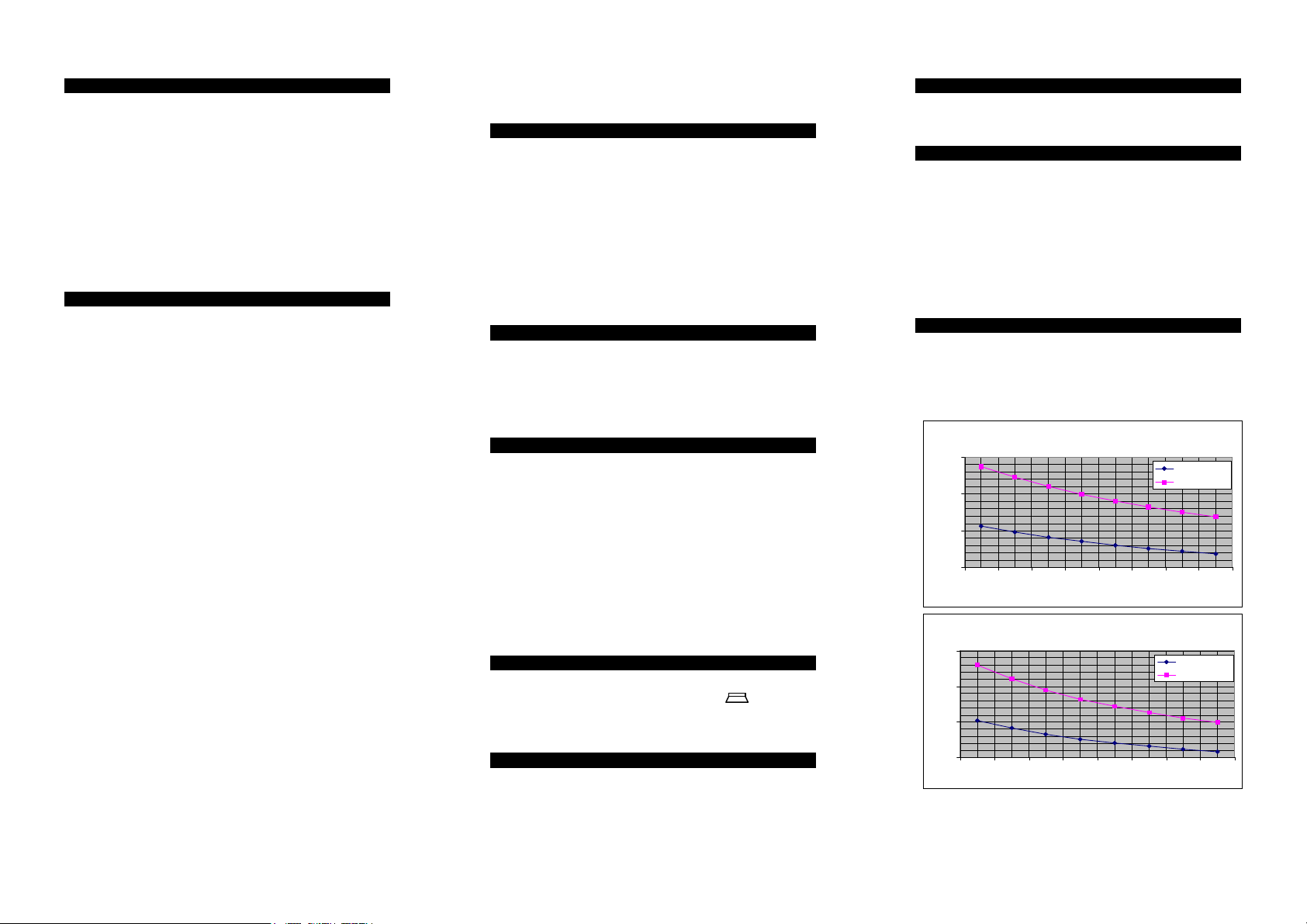
2.9 Battery
To ensure continuing protection in the event of mains
power failure a suitable rechargeable battery with a
capacity to support the system for a period of 12 hours
must be fitted.
Battery Backup Time Vs. Number of Passives (Passive
19
14
9
Backup Time in Hours
4
12 3456 78
Battery Backup Time Vs. Number of Passives (Passive
19
14
9
Backup Time in Hours
4
12345678
Curre nt=10ma )
1.2Ah B attery
2.1Ah B attery
Number of Passives
Current=15ma)
1.2Ah Bat tery
2.1Ah Bat tery
Nu m be r of Pa ssive s
NOTE: Calculations made for Avanti Compact with
onboard keypad using a neon sounder, assuming 1
complete alarm cycle of 20 minutes.
Page 3

3 Operation
3.1 Programs
The Avanti provides the facility for up to 3 programs that
can be selected by entering the A, B or * keys after
entering the user code when setting the system. The *
program is used for Full Set. If no program is selected
when setting the system the Avanti will default to
Program *.
When setting up the programs the function of each zone
can be changed i.e.: - Immediate, Timed, Time Inhibited
or Exit mode.
3.2 Operating
Setting the System
To set the system a user code (4 digits) must be entered
and a program selected (A,B or * [Full Set]). If no
program is selected within 5 seconds then the Avanti will
default to Program * (Full Set).
The exit timer will begin and a series of bleeps will sound.
Unsetting the System
To UNSET the system a user code must be entered, this
will return the panel to DAY mode. If the external siren is
sounding then entering the user code will silence the
sounder. All that is required to reset the system is to
enter a user code.
Fault during setting
If the system is unable to SET then the internal sounders
will make a different bleeping sound. The fault on the
system will be indicated by the relevant zone/PA/tamper
LED being lit.
Omitting Zones
To omit a zone a user code must be entered followed by
Z and then the zone number(s) to be omitted. The
zone(s) chosen to be omitted will be indicated by the
relevant zone LED being toggled off. A program should
then be selected. If a program is not selected then the
panel will default to Program *.
Quick Set
This feature allows the panel to be SET so that it
overrides the programmed exit time. Entering a User
code, selecting Program A/B or * and then pressing
will cause the panel to SET within 2 seconds.
3.3 Access Codes
Avanti has the following access codes:
1x Engineer Access code. 1x Holiday Access code.
1x Manager Access code 4x User Access codes.
Engineer Access Code – cannot be used to SET or
UNSET the panel, it can only be used to configure the
system and view the Event Log. Therefore it can only be
used from within DAY mode.
Manager Access Code – is used to SET and UNSET the
system. It also has the ability to change all other access
codes except for the engineers. The Manager is also able
to view the Event Log, test the system and programme
Chime for any zone.
Holiday Access Code – the purpose of this code is to
allow access to the property whilst the manager is absent.
The Holiday Access Code is programmed by the Manager
and is only valid until the Manager UNSETS the system.
At this point the Holiday Access Code becomes invalid and
is no longer accepted by the control panel.
User Access Code – allows the User to SET and UNSET
the system. Any User can also program Chime.
Additionally RS Panels have individual duress codes for
the Users, Holiday and Manager.
Duress is only accessible in SET. Entering a user code
followed by the first digit within 1 to 1.5 seconds will
activate a silent PA. i.e.: - 0 1 2 3 0
3.4 Keypad tamper
When the control panel is in SET, the Keypad tamper will
be activated after 20 invalid key presses. A full alarm
condition will then be created. (If you are using an RS
Panel fitted with a communicator then a signal will also
be sent.)
3.5 Entry Exit timers
The entry and exit timers have been factory set for 30
seconds. If you require more or less time then these
timers can be programmed independently via the keypad
in increments of 1 second from immediate to 99 seconds.
3.6 On Board PA
Simultaneously depressing key’s 4 and 8 will activate a
PA thus creating a full alarm condition. This feature can
be used when the system is in DAY mode or SET. (If you
are using an RS Panel fitted with a communicator then a
signal will also be sent.)
3.7 Service timer
The Avanti has provision for a service timer, which once
selected is fixed at 900 closings. When expired the
tamper LED will flash intermittently. The expiration of the
service timer will not
disable the control panel.
3.8 Non Volatile Memory (NVM)
The NVM circuit stores and protects the access codes and
system configuration information. To clear there are two
methods. i.e.: -
Method 1 From engineering mode pressing * twice
within 2 seconds will cause the panel to revert to factory
defaults whilst retaining the engineers access code.
Method 2 Remove power and remove link/wires
between T and A. Link Set+ to T with lid tamper closed
and power up the panel. The Avanti will retain all
information but will clear the engineer and manager
access codes.
3.9 Confirmed alarms (RS models only)
To reduce the level of false alarms the Avanti will only
send a confirmed signal to an Alarm Receiving Centre
(ARC) when 2 or more zones have been activated
sequentially.
3.10 Double knock
The Avanti range of panels can be programmed for
double knock. When a zone is activated a 10 minute timer
will begin, if during this time the same or another zone is
activated a full alarm condition will be caused. A zone
active for 10 seconds will also cause an alarm condition.
3.11 Bell follow
Bell Follow Off – If the system is activated then once
the bell has expired the strobe will continue to flash until
the system is reset.
Bell Follow On – If an alarm condition is caused then
the strobe will cease to flash at the same time as the bell
stops sounding.
Page 4

p
A
A
4 Engineer Programming
Once the engineers access code (9999) has been entered
from within DAY mode, the Day LED will be extinguished,
and all 8 Zone LED’s will flash to prompt for the selection
of the menu setting to be changed.
The following is a list of configurable menus available
within the engineers menu.
• Press 1 to Set up the Programs.
• Press 2 to Set up Zone Attributes.
• Press 3 to Set up the Exit timer.
• Press 4 to Set up the Entry timer.
• Press 5 to Set up Bell Active time.
• Press 6 to Set up Bell Delay time.
• Press 7 to Set up Access codes.
• Press 8 to Set up the Service Timer.
• Press 9 to Enter the Test Menu.
• Press 0 to Set up the System Flags.
• Press Z to Exit back to DAY mode.
• Press * twice within 2 sec’s for Factory Reset.
• Press
FACTORY DEFAULTS
1 User code 1 0123
2 User code 2 not used
3 User code 3 not used
4 User code 4 not used
5 Holiday code not used
6 Manager code 8888
7 Engineer code 9999
Entry time 30 secs
Exit time 30 secs
Bell delay 0 secs
Bell time 14 mins
Flags
Bell follow off
PTS in
Program
Z1 Timed
Z2 Time inhibited
Z 3-7 Immediate
Exit mode: Timed
Program
Z1 Timed
Z2 Time inhibited
Z3-5 Immediate
Z6-7 not used
Exit mode: immediate
to View the Event Log.
ut = PTS
*
Z1:
Omit enabled
Double knock disabled
Normally closed loop
Zone enabled
Not a fire zone
Chime zone
Not a doorbell
Z2,Z3,Z4,Z5,Z6,Z7:
Omit enabled
Double knock disabled
Normally closed loop
Zone enabled
Not a fire zone
Not a chime zone
Not a doorbell
Z8:
Omit enabled
Double knock disabled
Normally open loop
Zone enabled
Not a fire zone
Not a Chime zone
Doorbell
Program
Not initialised
B
Once a change has been made you need to accept or
abort the changes. Pressing Key A accepts the change
and returns you to the main engineer menu. Pressing Key
B aborts the change and returns you to the main
engineer menu. Within some menus Pressing A or B will
only return you to the top of that menu and Key Z needs
to be selected to return to engineers menu (this is
identified throughout programming guide).
4.1 Setting Up Programs.
Set-up Programs menu is entered from the Engineers
menu, by pressing Key 1.
When the Set-up Programs menu has been selected, Day,
PA and Tamper LED’s will flash to prompt the engineer to
select which of the 3 programs to set up.
Press A To Set program A.
Press B To Set program B.
Press * To Set program *.
Once the program that needs to be altered has been
selected, the following status LED’s will light.
DAY LED means Program A Selected.
PA LED means Program B Selected.
TAMPER LED means Program * Selected.
Zone Lights 1 to 4 will flash to prompt for a selection of
keys 1 to 4 to program the relevant program settings.
Press 1 To Set-up Immediate zones.
Press 2 To Set-up Timed Zones.
Press 3 To Set-up Time Inhibited zones.
Press 4 To Set-up the Exit Mode.
Press Z To return to Engineer Menu
4.1.1 Setting Up Immediate Zones
On entering Set-up Immediate Zones, the zones that are
currently set-up as immediate zones will have their
respective zone LED’s lit.
Pressing the key number that represents the zone to be
added or removed from the list of immediate zones will
toggle whether that zone is an immediate zone or not.
The zone LED will be lit if it is set as an immediate zone,
and extinguished if not.
Press A To Accept / B To Abort the changes.
4.1.2 Setting Up Timed Zones
On entering Set-up Timed Zones, the zones that are
currently set-up as timed zones will have their respective
zone LED’s lit.
Whether a zone is a timed zone or not is carried out in the
same way as immediate zones, by pressing the key
number for the zone that needs to be toggled to become
a timed zone or not.
Press A To Accept / Press B To Abort the changes.
4.1.3 Setting Up Time Inhibited Zones
On entering Set-up Time Inhibited Zones, the zones that
are currently set-up as time inhibited zones will have their
respective zone LED’s lit.
Whether a zone is a time inhibited zone or not is carried
out in the same way as immediate zones, by pressing the
key number for the zone that needs to be toggled to
become a time inhibited zone or not.
Press A To Accept / Press B To Abort the changes.
4.1.4 Setting Up the Exit mode
On entering Set-up the Exit mode, zone LED’s 1, 2, 3, or
NONE will be lit. The function represented by the LED’s is
as follows:
LED 1 = Timed exit.
LED 2 = Final Door set.
LED 3 = Immediate/Silent set.
NO LEDS means this program is disabled.
Press 0 To Select no exit mode.
Press 1 To Select Timed exit mode.
Press 2 To select Final Door set mode.
Press 3 To select Immediate/Silent set mode.
Press Z To return to Engineer Menu.
Press A To Accept / Press B To Abort the changes.
Page 5

4.2 Setting Up Zone Attributes.
Set-up Zone Attributes menu is entered from the
Engineers menu, by pressing Key 2.
Each of the zones has 9 Attributes that dictate its
function, that are fixed regardless of what the program
set-up has.
On entering the set-up Zone Attributes menu, the Day
LED will flash, along with all 8 zone LED’s. This is to
prompt the engineer to select the zone number for
which to set the attributes.
Once the zone number is entered, the Day LED will stop
flashing and the zone LED’s will be lit according to the
zone attributes that are selected. The attributes are as
follows:
Zone LED 1 – On for Chime. (Key 1)
Zone LED 2 – On for OMIT. (Key 2)
Zone LED 3 – On for double knock. (Key 3)
Zone LED 4 – On for normally open loop. (Key 4)
Zone LED 5 – On for Fire Zone. (Key 5)
Zone LED 6 – On for Doorbell. (Key 6)
Zone LED 7 – Not Used.
Zone LED 8 – On for zone disabled. (Key 8)
Tamper LED – On for Utility output A. (Key 9)
PA LED – On for Utility output B. (Key 0)
Pressing the Key number that represents the LED number
will toggle that attribute.
Press A To Accept / Press B To Abort the changes.
This will then return the engineer back to the Engineers
Menu.
4.3 Setting Up the Exit timer.
Set-up Exit Timer menu is entered from the Engineers
menu by pressing Key 3.
The Exit timer may be programmed from 0 seconds to 99
seconds.
On entering the set-up Exit timer menu, the Day LED will
be extinguished, and Zone 1 & 2 LED’s will light, to
prompt for a 2-digit number between 00 and 99 for the
Exit time in seconds. Once the 2-digit time has been
entered, the PA and TAMPER LED will flash prompting
the engineer to:
Press A To Accept / Press B To Abort the changes.
4.4 Setting Up the Entry timer.
Set-up Entry Timer menu is entered from the Engineers
menu, by pressing Key 4.
The entry timer may be programmed from 0 seconds to
99 seconds.
On entering the set-up Entry Timer menu, the Day LED
will be extinguished, and Zone 1 & 2 LED’s will light, to
prompt for a 2-digit number between 00 and 99 for the
Entry time in seconds. Once the 2-digit time has been
entered, the PA and TAMPER LED will flash prompting
the engineer to:
Press A To Accept / Press B To Abort the changes.
4.5 Setting Up the Bell Active timer.
Set-up Bell Active Timer menu is entered from the
Engineers menu, by pressing Key 5.
The Bell Active Timer may be programmed from 0 Minutes
to 99 Minutes.
On entering the set-up Bell Active Timer menu, the Day
LED will be extinguished, and zone 1 & 2 LED’s will light,
to prompt for a 2-digit number between 00 and 99 for the
Bell Active time in minutes. Once the 2-digit time has
been entered, the PA and TAMPER LED will flash
prompting the engineer to:
Press A To Accept / Press B To Abort the changes.
4.6 Setting Up the Bell Delay timer.
Set-up Bell Delay Timer menu is entered from the
Engineers menu, by pressing Key 6.
The Bell Delay Timer may be programmed from 0 Minutes
to 99 Minutes.
On entering the set-up Bell Delay Timer menu, the Day
LED will be extinguished, and zone 1 & 2 LED’s will light,
to prompt for a 2-digit number between 00 and 99 for the
Bell Delay time in minutes. Once the 2-digit time has been
entered, the PA and TAMPER LED will flash prompting
the engineer to:
Press A To Accept / Press B To Abort the changes.
4.7 Programming Access codes.
Programming Access Codes is entered from the Engineers
menu by pressing Key
7
Once the Programming Access codes menu has been
entered then the Access code to be changed must be
selected. The Day LED and zone LED’s 1 to 7 will flash to
prompt the selection of access codes 1 to 7. The access
codes are selected as follows:
Press 1 To Program User Access code 1.
Press 2 To Program User Access code 2.
Press 3 To Program User Access code 3.
Press 4 To Program User Access code 4.
Press 5 To Program the Holiday code.
Press 6 To Program the Manager code.
Press 7 To Program the Engineer code.
Once the Access code to change has been selected, the
Day LED will light constantly, and zone LED’s 1 to 4 will
light to prompt for the 4 digit access code to be entered.
For every key pressed, 1 zone LED will be extinguished,
indicating the number of digits left to enter of the access
code.
Once all 4 digits of the access code have been entered, all
of the zone LED’s will be extinguished, and the PA and
Tamper LED’s will be flashing.
Press A To Accept / Press B To Abort the changes.
4.8 Setting Up the Service timer.
Set-up Service Timer menu is entered from the Engineers
menu by pressing KEY 8.
The service timer is pre-set to 900 closings. The engineer
has the option of:
1. Enable or disabling the service timer.
2. Resetting the service timer.
On entering the service timer menu the zone LED’s have
the following meaning:
LED 1 Service Timer enabled.
LED 2 Service Timer disabled.
LED 3 Service Timer Expired.
Press 1 To Enable the service timer.
Press 2 To Disable the service timer.
Press 3 To Reset and enable the service timer.
Once a key has been pressed, there will be an
acknowledgement bleep, and then the panel will be
returned back to the engineers menu.
Page 6

4.9 Test Menu.
The Test Menu is entered from the Engineers menu by
pressing Key 9. The alarm panel has several test modes
making life a little easier for the installation engineer.
They are as follows:
• Press 1 to switch bell drive on.
• Press 2 to switch strobe drive on.
• Press 3 to switch all speakers on.
• Press 0 to switch all outputs off.
• Press 6 to enter walk test.
• Press 9 to show zone status.
• Press Z To Exit the Walk Test menu.
On entering the Test menu, All the zone LED’s will be
switched off, and the PA and Tamper LED’s will be
flashing, indicating a test must be selected.
WALK TEST.
On entering the zone walk test, all of the zones will be
reset, and all zone LED’s will be switched off. The PA and
Tamper LED’s will be flashing indicating that the engineer
is within the walk test function.
Each time a zone is activated or de-activated the internal
sounders will bleep. When a zone becomes active, the
zone LED’s for all active zones will be lit.
Press Z To exit walk test. This will move you back to the
test menu, the PA and Tamper LED’s will flash. To return
to Engineer Menu Press Key Z.
4.10 Setting Up the System Flags.
Set up System Flags menu is entered from the Engineers
menu, by pressing KEY 0.
There are 3 system flags that can be set to tailor the way
that the system operates.
On entering the set-up system flags menu, zones 2 and 3
LED’s will be lit according to the zone attributes that are
selected. The flags are as follows:
LED 2 On for Bell follow.
LED 3 On for Key switch operation (PTS input).
LED 3 Off for Push to set (PTS input).
Pressing the Key number that represents the LED number
will toggle that attribute.
Press A To Accept / Press B To Abort the changes.
4.11 Viewing the Event Log.
The Event Log menu is entered from the engineers menu,
by pressing
key.
The Day LED will be extinguished to indicate Event Log
mode.
The Zone, PA and Tamper LED’s will now show the latest
event. Whichever Zone, PA or Tamper LED is flashing is
the first activated, and whichever Zone, PA or Tamper is
lit was triggered after the first event, but before the
system was un-set.
To navigate through the event log, the following keys are
used:
Press 1 To Jump to the oldest event.
Press 2 To move to 1 event older.
Press 3 To move to 1 event newer.
Press 4 To Jump to the newest event.
Press 9 To Reset the event log.
Press Z To Return to Engineer Menu.
If there are less than 16 events, then it is only possible to
scroll between the number of events within the event log.
4.12 Changing Chime in Day Mode
Chime is a low security attribute that can be programmed
onto any zones. In Day mode, the Chime Attribute for
each of the 8 zones may be changed in the following
manner:
Press
All of the zones that will chime when they are activated
will have the LED for that zone lit up.
Press the key that represents the zone that the zone
attribute requires changing for. This will toggle the LED
for that zone. When the LED is lit, that zone will chime
when it is activated.
Once the changes have been made then:
Press A To Accept / Press B To Abort the changes.
5 Remote signalling
Communicator Terminals
The RS variant of the control panel is fitted with
communicator outputs on the top left side of the PCB.
13V output
This output, along with the 0V output provides power for
a wire on communicator, which is fused at 0.5A.
Note: Care should be taken to ensure that the maximum
load on the power supply is less than 350ma for auxiliary
devices such as communicators, passives but excludes the
Bell/Strobe outputs.
Line Fail
This input allows the communicator to inform the panel
that there is a line fault.
When the panel is in DAY mode a line fail will cause the
Tamper LED to flash but will not cause an alarm.
A line fault when the panel is SET will not cause an alarm,
but will cancel any bell delay programmed into the panel.
Outputs
There are 6 outputs labelled FIRE, PA, INT, SET,
ABORT, and CONF. Each output sits at 12V when not
active and is pulled to approximately 0.8V when active.
Each output can sink 50ma, giving enough energy to drive
a relay if required. These outputs would normally be
connected to a STU or communicator.
FIRE – This output becomes active (0V) when the panel
is activated by a fire input.
PA – This output becomes active (0V) when the panel is
triggered by:
INT – This intruder output becomes active (0V) when the
panel is triggered whilst the panel is SET.
SET – This output becomes active (0V) when the panel is
SET.
ABORT – This output becomes active (0V) when an alarm
condition is reset.
CONF – This confirmed output becomes active (0V) when
2 or more zones are triggered when the panel is SET.
Note: If the communicator or STU is being powered by a
separate power supply, the 0V of the external power
supply must be connected to the 0V of the alarm panel.
1) PA input becoming active
2) Duress code being entered
Page 7

y
y
/
/
g
g
S
t
T
S
d
13
PTS
Ab
t
12
PA
INT
L
F
il
RKP C
V
l
t
l
T
5.1 Communicator Test Menu
It is imperative that the system is fully tested before
connecting to a communicator or STU and that the Alarm
Receiving Centre (ARC) is receiving signals correctly.
The Communicator Test menu is entered from the
Engineers menu by pressing Key 9 (Test Menu) and then
Key 4. All zone LED’s will be switched off with Day, PA,
Tamper and Power LED’s all steady.
Press 1 to test Fire output.
Seconds
Seconds
Timer
Exit Timer
Entr
Minutes
Bell Dela
Bell Timer
Minutes
Installation date
ineer
En
Press 2 to test PA output.
Press 3 to test Intruder output.
Press 4 to test Open/Closed output.
Press 5 to test Abort output.
Press 6 to test Confirmed outputs.
Press 0 to switch communicator outputs off.
Press Z twice to return to Engineers Menu.
Area Covered
Detectors
Lo
Resistance
Contact
Site address
Zone 1
Zone 2
Zone 3
Zone 4
Zone 5
Zone 6
Zone 7
Zone 8
Cut to
disable
backlighting
DAY PA
TAMPER POWER
ZONES
1 2 3 4 5 6 7 8
a
v
0v
Comms Connections
or
Conf
Set
Fire
Bell O/P fuse
500mA QB
RKP fuse
500mA QB
amper
v
~
switch
0v
~
Battery fuse
1.A QB
ro
ume con
o
oun
Comm
onnections
Batt
+ -
Zone 8
Zone 7
Zone 6
Zone 5
Zone 4
Zone 3
Zone 2
Zone 1
Tamp
PA
- +
Strobe
B D
T A
Bell Connections
- +
e
amp
Tamp
+
Page 8

Due to continuous product development, we reserve the
right, without prior notice, to alter specifications as and
when required.
Tel: +44 (0) 1305 853 090
Fax: +44 (0) 1305 851 660
e-mail: sales@keystone-electronics.co.uk
 Loading...