

Page 1

www.avantiproducts.com
O
■o
■
3
O
iS
c5
00
MODEL
H2311W
H2312SS
■o
C
03
C)
O
C)
(/)
Model number:
Serial number:
08/05 Rev:1 ® Avanti
Page 2

www.avantiproducts.com
Page 3

j2
INSTALLATION
Specifications
FEATURES & CONTROLS
Controls Overview.
MAINTENANCE
Cleaning
Lights......................
TROUBLE SHOOTING
.................
..............
...2
...3
...4
...5
6
...7
...8
...9
...10
...11
...12
...12
...13
...14
...15-16
c
0)
c
o
o
o
0)
(0
Page 4

READ AND SAVE THESE INSTRUCTIONS
WARNING
8
TO REDUCE THE RISK OE EIRE OR ELECTRIC SHOCK, DO NOT US E THIS LAN WITH ANY SOLID-STATE
SPEED CONTROL DEVICE.
WARNING
TO RE DUCE THE RISK OE EIRE, ELECTRIC SH OCK, OR INJURY TO PERSONS, OBSERVE THE EOLLOWING:
a. Use this unit only in the manner intended by the manufacturer. If you have questions, contact the manufacturer.
b. Before servicing or cleaning unit, switch power off at service panel and lock the service disconnecting means to prevent power from being
switched on accidentally.
When the service disconnecting means cannot be locked, securely fasten a prominent warnintj device, sucfi as tag, to thr; service; panel.
www.avantiproducts.com
'c5
(/>
t
0)
c
(0
o
D.
E
CAUTION
Eor General Ventilating Use Only. Do not Use to Exhaust Hazardous or Explosive Materials and Vapors.
Take care when using cleaning agents or detergents.Suitable for use in household cooking area.
WARNING
TO REDUCE THE RISKOE A RANGE TOP GREASE EIRE:
a. Never leave surface units unattended at high settings. Boilovers cause smoking and greasy spillovers that may ignite. Heat oils slowly on low
or medium settings.
b. Always turn hood ON when cooking at high heat or when cooking flam being food (i.e. Crepes Suzette, Cherries Jubilee, Peppercorn
Beef Elambe)
c. Clean ventilatincj fans frequently. Grease; shoulcJ not be; allowecJto accumulate; on fan or filter
d. Use proper pan size. Always use cookware appropriate;for the size of the surface element.
e. Keep fan, filters and grease laden surfaces clean.
f. Use high setting on hood only when necessary.
g. Don’t leave hood unattended when cooking.
h. Always use cookware and utensils appropriate for the type of and amount of food
being prepared.
WARNING
TO REDUCE THE FilSKOE INJURY TO f^ERSONS IN THE EVENT OE A RA NG E TOP GREASE EIRE, OBSERVE THE EOLLOWING:
a. SMOTHE R ELAMES with a close-fitting lid, cookie sheet, or metal tray, then turn off the burner. BE CARE EUL TO PREVENT BUR NS.
If the flames do not go out immediately, EVACUATE AND CALL THE EIRE DEPARTMENT.
b. NEVER PICK UP A ELAMING PAN - You maybe burned.
c. DO NOT USE WATE R, including wet dishclothes or towels - a violentsteam explosion will result.
d. Use an extinguisherONLY if:
1. You know you have a class ABC extinguisher, and you already know howto operate it.
2. The fire is small and contained in the area where it started.
3. The fire department is being called.
4. You can fight the fire withyour back to an exit.
5. Based on "Kitchen Eire Safety Tips" published by NEPA.
WARNING .
TO REDUCETHE RISKOE EIRE, ELECTRIC SHOCK OR INJURY TO PERSONS, OBSERVE THE EOLLOWING:
a. Installation Work and Electrical Wiring Must be Done by Oualified Person (s) In Accordance with all Applicable Codes and Standards,
Including Eire-Rated Construction.
b. Sufficient air is needed for proper combustionand exhausting of gases throughthe flue (chimney) of fuel burningequipmen1:to prevent back
drafting, follow the heating equipmentmanufacturer's guideline and safety standards such as those published by the National Eire Protection
Association (NEPA), and the American Society for Heating, Refrigeration, and Air ConditionincjEngineers (AS HRAE) and the local code authorities
c. When cutting or drilling into wall or ceiling, do not damage electrical wiring and other hidden utilities.
d. Ducted fans must always venttothe outdoors.
e. Ifthis unit is to be installed over a tub or shower, it must be marked as appropriate for the
application and be connected to a GFCL (Ground Fault Interrupter protected branch circuit).
g. NEVER place a switch where it can be reached from a tub or shower.
h. Make sure the power is off before installing, wiring or maintenancing.
WARNING
TO REDUCE THE RISKOE EIRE, USE ONLY METAL DUCTWORK.
CAUTION
To reduce risk of fire and to properijrexhaust air, be sure to duct air outside - Do not vent exhaust air into spaces within walls or ceilings or into
attics, crawl spaces or garages.
Page 5

1 - Hood
2-Light bulbs, 40W R16
2 - Metallic Mesh Filters
1 - 3 1/4” X 10” rectangular starting collar with damper
1 - Air Recirculation Kit (pre-installed)
1 - Charcoal Filter
1 - Air Diverter Plate (must install for use in ducted mode)
1 - Charcoal Filter Holder
1 - Air Recirculation Louver Plate
1 - Air recirculation Cover Plate (for use in ducted mode)
1 - Hardware packet containing:
3 - Wire connector caps 18g
4 - Wood Screws 2”
4 - Wood Screws 1 1/2”
4 - Wood Screws 1 ”
4 - Washers
N0 DUCTING IS INCLUDED
(0
0)
IS
s
o
%
* Note:
but are readily available at most hardware stores.
Use 50LB EZ anchors if mounting hood onto drywall. These are not provided,
Page 6
(/>
0)
0)
c
o
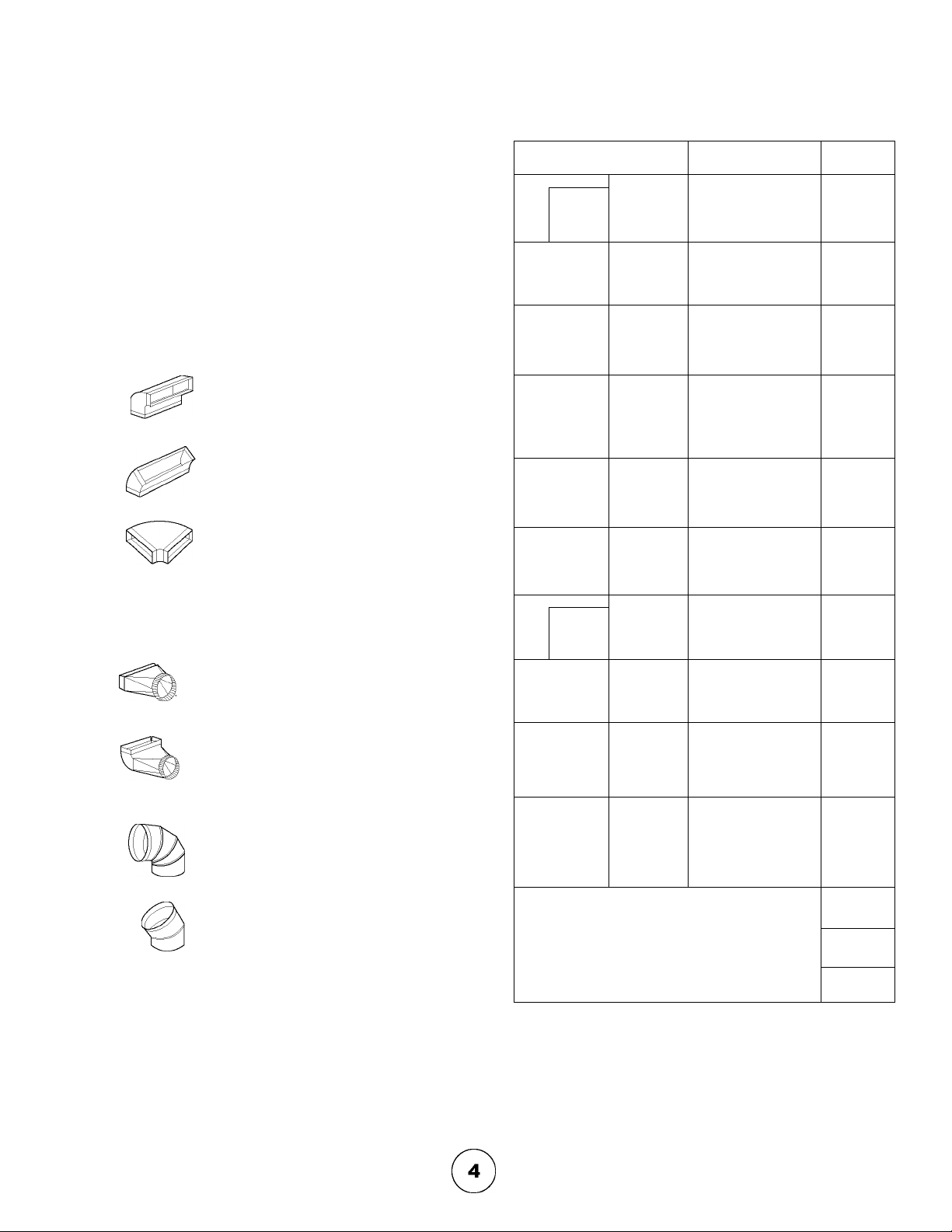
Duct Attachments Not Included
Duct pieces
3 1/4" X 10"
Rect.,
straight
7" Round,
straight
Equivalent number
length X used =
1 Ft. X (
1 Ft. X (
Total
Ft.
Ft.
Duct pieces
c
www.avantiproducts.com
6" Round
wall cap
with damper
6" Round,
roof cap
Equivalent number
length X used =
30 Ft. x( ) =
30 Ft. x( ) =
Total
Ft.
Ft.
o
1
Ü
Q
3
Ü
(0
0
o
7" Round,
straight
3 1/4" X 10"
Rect. 90 "
eibow
3 1/4" X 10"
Rect. 45 "
eibow
3 1/4" X 10"
Rect. 90 "
fiat eibow
1 Ft.
15 Ft.
9 Ft.
24 Ft.
3
3 1/4" X 10"
I
c
c
Rect.
waii cap
with damper
3 1/4" X 10"
Rect. to
6" round
transition
3 1/4" X 10"
Rect. to
6" round
transition
90° eibow
6" Round,
90° eibow
30 Ft.
5 Ft.
15 Ft.
15 Ft.
Ft.
Ft.
Ft.
Ft.
Ft.
Ft.
Ft.
Ft.
c
«a.
6" round to
3 1/4" X 10"
rect.
transition
6" round to
3 1/4" X 10"
rect.
transition
90° elbow
7" Round,
90° elbow
7" Round,
45° elbow
7" Round
wall cap
with damper
7" Round,
roof cap
7" round to
3 1/4" X 10"
rect.
transition
7" round to
3 1/4" X 10"
rect.
transition
90° elbow
1 Ft. X ( ) =
16 Ft. x( ) =
15 Ft. x( ) =
9 Ft. x( ) =
30 Ft. x( ) =
30 Ft. x( ) =
8 Ft. x( ) =
15 Ft. x( ) =
Ft.
Ft.
Ft.
Ft.
Ft.
Ft.
Ft.
Ft.
6" Round,
45° eibow
9 Ft.
Subtotal column 1 =
Maximum Duct Length: For satisfactory air movement,
the totai duct iength of a 3 1/4"x 10" rectangular, 6" or 7"
diameter round duct shouid not exceed 100 equivalent feet.
Ft.
Ft.
Subtotal column 2 =
Subtotal column 1 =
Total ductwork =
Ft.
Ft.
Ft.
Page 7

Minimum mount height between range top to hood bot
tom shouid be no iess than 24".
Maximum mount height shouid be no higher than 32".
0)
o
c
DUCTING
A minimum 3-1/4 x 10"rectanguiar duct
must be used to maintain maximum air
fiow efficiency.
it is important to instaii the hood at the proper mounting
height. Hoods mounted too iow couid resuit in heat
damage and fire hazard; whiie hoods mounted too high
wiii be hard to reach and wiii iose its performance and
efficiency.
if avaiiabie, aiso refer to range manufacturer's height
ciearance requirements and recommended hood
mounting height above range. Aiways check your iocai
codes for any differences.
Cut Out Size
24" 23 3/4"
Minimum Duct Size:
Rectangular- 3-1/4 x 10" minimum
(rear or top)
Net Width
s
(5
_g>
O
o3
U)
'o
U)
c
c
3
o
c
o
Aiways use rigid type metai ducts oniy.
Fiexibie ducts couid restrict air fiow by up
to 50%.
Use caicuiation worksheet to compute totai
duct work.
ALWAYS, when possibie, reduce the number
or transitions and turns, if a reducer is used,
instaii a iong reducer instead of a pancake
reducer. Reduce duct size as far away from
opening as possibie.
if turns or transitions are required:
instaii as far away from opening and as far
apart, between 2, as possibie.
DAMAGE-SHIPMENT/INSTALLATION:
• Piease fuiiy inspect unit for damage
before instaiiation.
if unit is damaged in shipment, return
the unitto the store in which it was
bought for repair or repiacement.
if the unit is damage by the customer,
repair or repiacement is the
responsibiiity of the customer.
if the unit is damage by the instaiier (if
other than the customer), repair or
repiacement must be made by
arrangemnt between customerand
instaiier.
%
c
Page 8

www.avantiproducts.com
Q
D)
C
0
3
1
c
o
c
WARNING FIRE HAZARD
NEVER exhaust air or terminate duct work into spaces between waiis, crawi spaces, ceiiing.attics or garages.
Aii exhaust must be ducted to the outside, uniess using the recircuiating option.
Use singie waii rigid Metai ductwork oniy.
Fasten aii connections with sheet metai screws and tape aii joints w/ certified Siiver Tape or DuctTape.
Some Ducting Options:
cabinet
air recircuiation
A
/p:
3 1/4" X 10" rear discharge
w/side waii gravity damper
■Tn
Page 9

Installation - Specifications
Page 10

Q
"O
www.avantiproducts.com
D)
C
o
3
c
(0
15
o
o
_g>
LU
(0
c
o
0
3
D?
c
1
c
o
1. Remove filters.
3. If using a cable lock (not provided) pry
open the desired electrical knockout, either
on the top or the back. Feed the wires
through the 3/4” cable lock. Note: Some
local codes require the use of a cable lock
check your local codes for this information.
'2.. Remove two phillips head screws and
cover from junction box to gain access
to eiectricai wiring.
4. If using hood in air recirculation mode,
skip steps 4 and 5.
Pry open the desired 3 1/4x 10”
ducting knockout, either on the top or the
back.
Cable lock example
lo
c
5. Attach the 3 1/4” X 10 starting collar
with damper to the duct opening you
exposed.
8
Page 11

If using hood in air recircuiation mode, skip these steps
0)
"O
o
"O
0)
0
3
Q
1
1. Pull up and twist the two spring loaded
clips around the carbon filter holder.
3. Insert air diverter plate and screw
into place.
2. Remove the carbon filter and carbon
filter holder.
4. Remove the air recirculation louver plate
on top of the hood.
c
o
c
5. Finally, attach the cover plate to the
top of the hood.
Page 12

www.avantiproducts.com
"O
ELECTRICAL-WARNING
o
o
0)
D)
c
c
3
o
c
All Electrical work must by performed by qualified
electrician or person with similar technical know how
and background.
For personal safety, remove house fuse or open circuit
breaker before beginning Installation.
Do not use extension cord or adapter plug with
this appliance.
Follow National electrical codes or prevailing local
codes and ordinances.
Electrical Supply:
This appliance requires a 120V 60Hz electrical supply.,
and connected to an Individual, properly grounded branch
circuit, protected by a 15 or 20 ampere circuit breaker or
time delay fuse. Wiring must be 2 wire w/ ground. Please
refer to Electrical Diagram labeled on product. You must
be a qualified technician ora service personnel to Install
this unit.
1. Temporarely position the hood in the
desired mounting location. Measure and
mark the mounting holes, duct and electri
cal access locations with a pencil. Remove
hood and drill/cut out the requirred open
ings for duct and electrical access.
o
c
2. Attach house electrical wiring to
hood wiring. Make sure the power source
is turned off before working with any
electrical wiring.
4. Attach duct work. Use aluminum duct
tape to make joints secure and air tight.
NOTE: This step is not necessary if hood is
in air recirculation mode.
3. Hang hood from mounting screws
provided. Slide hood toward wall until
mounting screws are engaged in narrow
end of keyholes. Tighten mounting screws
securely. CAUTION: Do not push on safety
grill when installing, this may result in
damage to the motor.
5. If not already done, install light bulbs by
screwing in clockwise.
10
Page 13

Blower On/Off/Speed Selection ^ Lights On/Off/Dim
o>
t
0)
>
O
o
^ Blower On/Off/Speed Selection
This switch turns the blower on and off and controls the speed selection.
0 is off, I is low speed, II is medium speed and III is high speed.
^ Lights On/Off/Dim
0 is off, I is bright, II is dim.
c
o
0
1
o
c
o
o
o8
tf>
0)
(0
0)
11
Page 14

www.avantiproducts.com
j5
"O
(0
3
U)
U)
c
o
a.
0)
c
(0
U)
c
Aluminum Mesh Filters:
Clean frequently using hot water and a mild, non abrasive detergent. Filters are dishwasher safe.
Carbon Filters:
Clean carbon filters holder frequently with a damp cloth and mild detergent. DO NOT Immerse carbon filter In water
or put In dishwasher. The carbon filters should be replaced every 4to6 months under normal use.
Hood Surface:
Remove filters. Use a damp cloth and a mild detergent to wipe all residue-laden surfaces. Use care when cleaning fan
blades, It must not become bent or misaligned. DO NOT ALLOW WATER TO ENTER MOTOR. Make sure surfaces
are completely dry before re-lnstalling filters and using hood.
Replacing Light Buibs:
CAUTION: Light bulbs become extremely hot when turned on. DO NOT touch bulbs until switched off and cooled.
Touching hot bulbs may cause serious burns.
Hood comes with (2) 40W medium base. Incandescent appliance bulbs.
Remove bulb by unscrewing counter-clockwise. Use a suction cup or rubber/latex glove to grip the bulb If removing bulb
Is difficult.
_0)
o
c
(0
0)
o
c
(0
c
0)
c
CO
12
Page 15

I. Upon completion of installation
nothing works.
Check if unit has been plugged in, make sure that all power has been
turned back on and all electrical wiring are properly connected.
D)
C
2. Light is on but blower is not
turning at all or seems to be
scraping on something.
3. When blower is on,
something seems to be loose
and spinning around inside.
4. Vibration when blower is on Unit might not have been secured properly on cabinet. Or cabinet
5. Blower noise Our blowers are designed to perform up to 280 cfm. A properly
6. Light is not working Light bulb might need to be replaced. On some instances, the fragile
7. Blower seems \A/eak Check duct size used, duct size should be at least 3 1/4" x lO".
Blower blade unit might have been mounted too low and scraping
the bottom or jammed. Loosen hex screw on blade unit and adjust to
proper height.
There might have been foreign particles left within the discharge
opening or rocks, leaves, branches, etc. that might have fell in from
old duct work. Disconnect duct work to inspect and remove any
foreign particles.
might need to be further secured into studs on wall.
functioning motor itself should be relatively quiet. Nevertheless, due
to vacuum created by the suction, noise level up to 4 sones will be
generated when blower unit is turned on at its maximum speed.
Employing low speeds will suffice moderate cooking such as steam
ing, broiling etc.
bulb could have been damaged during the shipping process.
Replace light bulb.
Range hood WILL NOT function properly with the insufficient
duct size.
Check if duct is clogged or if dumper unit is not opening properly. A
tight mesh on a side wall cap unit might also cause restriction to the
air flow.
Use a damper type sidewall cap.
Reduce the number of elbows and length of duct work or increase
duct size.
Check if all joints are properly connected, sealed and taped.
o
o
(/>
o
3
o
8. Cooking fumes and smoke
dissipates before it reaches
the blower.
Check if unit is installed at the recommended height. The range hood
should also be able to cover the entire cooking area from left to right
and most areas from rear to front.
Open doors and windows might also distract air flow before it reach
es the blower.
Make sure blowers are on high speed for heavy cooking.
13
Page 16

www.avantiproducts.com
C
SH
(5
TO OBTAIN SERVICE UNDER WARRANTY:
or any Service Related Questions, please call:
1-800-220-5570
Staple your receipt here.
Proof of the original purchase
date is needed to obtain service
under the warranty.
TO OBTAIN SERVICE UNDER WARRANTY: You must present proof of original purchase date.
Please keep a copy of your dated proof of purchase (sales slip) in order to obtain service under warranty.
One Year Service Repair Warranty:
For one year from date of original purchase, we will provide free of charge, service labor to repair any failed parts or
components due to manufacturing defects.
Two Year:; Part:; Warranty:
Fortwoyears from date of original purchase, we will provide free of charge, nonconsumable replacement parts or
components that failed due to manufacturing defects. Consumable parts not covered by this warranty include: Light Bulbs,
Metal and Carbon Filters.
Who is Covered:
This warranty is extended to the original purchaser for products purchased for ordinary home use in the 48 mainland states,
Hawaii and Washington D.C. In Canada and Alaska, this warranty Is Limited. There might be costs associated with
shipping the products to our designated service locations or you might need to pay service technician's travel costs, to have
the appliance repaired In-home.
This Warranty will be Voided when:
Product damaged through negligence, misuse, abuse, accident. Improper installation and failure to follow installation instruc
tions. When product is used commercially or other than its intended purpose. Damaged because of improper connection with
equipment of other manufacturers. Repaired or modified by anyone other than Avanti's Authorized Agents.
What is Not Covered:
Consumable parts such as light bulbs, filters, and fuses. Services outside of service area and the labor cost incurred in
connection with the removal, shipping and reinstallation cost, nor does it cover any other contingent expenses. The natural
wear of finish, and wear due to improper maintenance, use of corrosive and abrasive cleaning products, pads, and oven
cleaner products. Chips, dents or cracks due to abuse, misuse, freight damage, or improper installation. Service trips to your
home to teach you how to use the product. Damage of product caused by accident, fire, floods or act of God.
This warranty is valid in the United States and Canada. It is non-transferable and applies only to the original purchaser and does not extend to
subsequent owners of this product. Any applicable implied warranties, including the warranty of merchantability, are limited in duration to a period
of express warranty as provided herein beginning with the date of original purchase at retail and, no warranties, whether express or implied, shall
apply to this product thereafter.
Have your product proof of purchase with date ready for warranty issues.
Or write to:
Customer Service
Avanti Products
10880 NW ;50 Street
Miami, FL 331712
Page 17

(Jl
o
<
o
iD
o
U1
7J
(D
<
!=C!
IND
CO
, ro
ro o>
Exploded View Diagram - H2311W/ H2312SS
Page 18

CO
CM
(0
0
n
E
t:
(C
Q.
www.avantiproducts.com
H2311W
Spare Parts List
Ref# Part#
1
3
4
5
6 HXP001211-27 Motor Holder 1
7
8
10
11
12
13 XP018133-2
14
15 XP018133-4 Carbon Filter Grille 1
16
17
18
19
20 XP01868-14 Slide Switch Gasket-B (Fan) 1
21
26
28 XP02802-4 Capacitor 4.5uf/300v 1
29
30 XP02901-2 Light socket, left 1
40 XP13804-1 Light Bulb, R14,120V 40W 2
41
42
43
44
45 XP14438-7
46 XP14444 Light cover 2
52
53
54
61 XP22302 Carbon Filter 1
63
64
65
66
M033
HXP001211-13
HXP001211-16 Left side panel
HXP001211-19 Right side panel
XP00613
XP00613-1
XP018111 Residue Secure Switch
XP018133
XP018133-1
XP018133-3 Residue Pan
XP01868
XP01868-03
XP01868-06
XP01868-09
XP021174-2
XP02746-3 Electrical wires
XP02901-1
XP14438-1
XP14438-2
XP14438-3
XP14438-4
XP164190-05A
XP164190-29 Top Cover Plate
XP164190-33
XP26501 Fan Blade
XP26601
XP26603 Fan Blade cover panel
XP26701-1 Metal Filter
Description
per Hood
Motor 1
Support Panel 1
Slide switch, motor 1
Slide switch, light 1
Air diverter panel 1
Air diverter panel cover 1
Blowerwheel cover
Slide Switch Gasket-W (Light) 1
Slide Switch Stem - W (Fan) 1
Slide Switch Stem - W (Light) 1
Switch Spacer 1
Decal
Light socket, right 1
Junction Box Cover 1
Control Cover
Light Housing 2
Blowerwheel
Air Recirculation cover plate (W)
Hood Body
Light Panel (W) 1
Rectangular Starting Collar 1
1
1
1
1
1
1
1
1
1
1
1
1
1
1
2
Page 19

www.avantiproducts.com
H2312SS
Spare Parts List
Ref# Part#
1
3
4
5
6 XP001211-27 Motor Holder 1
7
8
10
11
12
13 XP018133-2 Blower wheel cover 1
14
15 XP018133-4 Carbon Filter Grille 1
16
17
18 XP01868-07 Slide Switch Stem - B (Light) 1
19
20 XP01868-12 Slide Switch Gasket-B (Fan) 1
21
26
28 XP02802-4 Capacitor 4.5uf/300v 1
29
30 XP02901-2 Light socket, left 1
40 XP13804-1
41
42
43
44
45
46 XP14444 Light cover 2
52
53
54
61 XP22302 Carbon Filter 1
63
64
65
66
M033
XP001211-13
XP001211-16 Left side panel
XP001211-19 Right side panel
XP00613
XP00613-1
XP018111 Residue Secure Switch
XP018133
XP018133-1
XP018133-3 Residue Pan
XP01868-01
XP01868-04 Slide Switch Stem - B (Fan) 1
XP01868-10
XP021174
XP02746-3 Electrical wires
XP02901-1
XP14438-1
XP14438-2
XP14438-5
XP14438-4 Blower wheel 1
XP14438-6
XP001211-02
XP001211-28 Top Cover Plate
XP001211-32
XP26501 Fan Blade
XP26601
XP26603 Fan Blade cover panel
XP26701-1 Metal Filter
Description
per Hood
Motor 1
Support Panel 1
Slide switch, motor 1
Slide switch, light 1
Air diverter panel 1
Air diverter panel cover 1
Slide Switch Gasket-B (Light) 1
Switch Spacer 1
Decal
Light socket, right 1
LightBulb, R14,120V40W
Junction Box Cover 1
Control Cover
Light Housing 2
Air Recirculation cover plate (B) 1
Hood Body
Light Panel (S)
Rectangular Starting Collar 1
CO
CO
CM
CO
CM
1
1
(0
0
n
E
2
t:
1
1
1
2
1
1
1
1
1
1
2
(C
CL
 Loading...