

Page 1
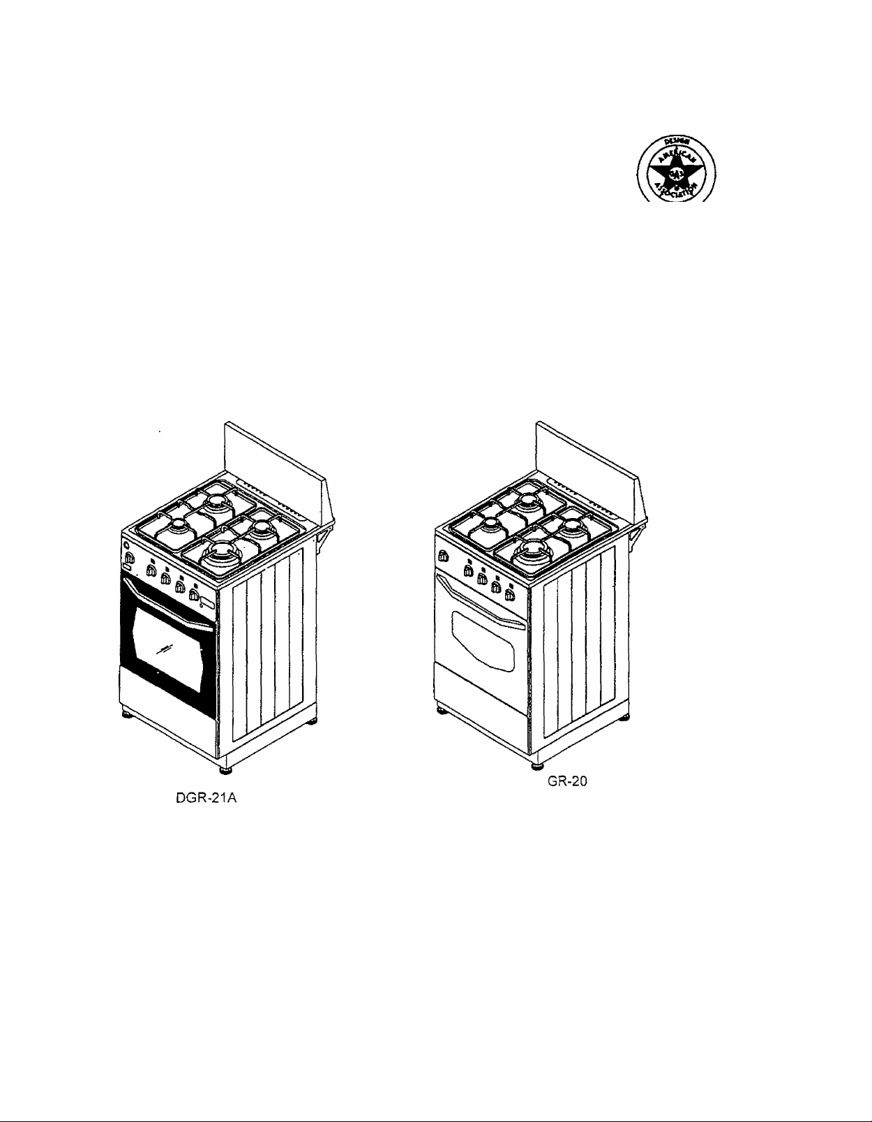
Model Numbers:
GR-20
DGR-21A
GAS RANGE
INSTRUCTION MANUAL
CAUTION:
BEFORE USE, PLEASE READ AND FOLLOW ALL SAFETY RULES AND OPERATING
INSTRUCTIONS.
Avanti Products, A Division of The Mackie Co., Inc.
P.O. Box 520604 - Miami, Florida 33152
www.avantiproducts.com
Page 2

IMPORTANT SAFETY INSTRUCTIONS
Gas ranges have been thoroughly tested for safe and efficient operation. However, as with any
appliance, there are specific installation and safety precautions that must be followed to ensure safe
and satisfactory operation.
WARNING
To reduce the risk of fire, electrical shock, or injury when using your gas range, follow these
precautions:
• Read all instructions before using this appliance.
• Grounding instructions
This appliance must be grounded. In the event of an electrical short circuit, grounding
reduces the risk of an electrical shock. This appliance is equipped with a three-prong cord
with a ground plug. Do not, under any circumstances, cut or remove the ground prong from
the power cord supplied with this appliance. This appliance must be plugged into an outlet
that is properly grounded. Do not use an adapter plug. Using an extension cord is not
recommended. Consult a qualified electrician for any questions as to whether your home or
business has the proper electrical grounding connections.
• Child Safety
An empty appliance can be a dangerous attraction to a child. Never allow children to play
with or crawl inside the appliance. Remove the door, door gasket, latches, or lids before
storing or abandoning the appliance.
• Never clean the appliance with flammable liquids. The fumes can create a fire hazard or
explosion.
• Do not store or use gasoline or other flammable products in the vicinity of this appliance. The
fumes can create a fire hazard or explosion.
A WARNING
Tip Over Hazard
Connect anti-tip bracket to the range back.
Reconnect anti-tip bracket if the range is moved.
Do not push down on the open oven door.
Follow the installation instructions.
Do not let children climb onto the oven door.
Failure to do so can result in death, burns, or other injury.
For more information see Anti-Tip Bracket Installation on Page 7.
A WARNING: If the information in this manual is not followed exactly, a fire or explosion
may result causing property damage, personal injury or death.
-Do not store or use gasoline or other flammable vapors and liquids in the vicinity of this
or any other appliance.
-WHAT TO DO IF YOU SMELL GAS
(3) Open windows.
CD Do not try to light any appliance.
(D Do not touch any electrical switch; do not use any phone in your building.
CD Immediately call your gas supplier from a neighbor’s phone. Follow the gas supplier’s
instructions.
(D If you cannot reach your gas supplier, call the fire department.
- A qiialifipri installnr Rprvir.p agr^nny nr thn gas siippljnr nnnc;i pnrfnrm in.«itallRtinn anr|
service.
Page 3

Table’of Contents
Important Safety Instructions,
Before Using Your Gas Range
Installation Requirements for Your Gas Range
Material Requirements
Space Requirements
Gas Requirements________________________
Electrical Requirements
Installation of Your Gas Range
Leveling of Range
Backguard
Anti-Tip Bracket,
Gas Connection
Electrical Connection
Mobile Home Installation
Operating Your Gas Range,
Operation of Surface Burners
To Light the Desired Surface Burner,
Operation of Oven Burner
Using Your Oven
Oven Light
CIock/Timer
Broiler Burner {DGR-21A Only)
Care and Maintenance ______
Removing Door for Cleaning
Cleaning Your Oven
Cleaning the Knobs and Control Panel
Cleaning the Utensil Supports, Cooktop, Backguard, and Surface Burners,
Converting Gas Type __________________________________________________
Pressure Regulator____________________________________________________
Burner Valves
Surface Burners.
Oven Burners
Broiling Burner {DGR-21A Only)
Troubleshooting Guide
Service For Your Gas range,
Your Avanti Products Warranty
Warranty Information and Registration Card
Help Us Help You
Parts and Features
Wiring Diagrams
_________
________________
__________________
________________________
_______
_________________________________________________________
_________________________
_
______________
___________________
_____________________
_____
_________
________________________________
__________
_ 2
_ 4
_ 4
_ 4
_ 5
_ 5
, 5
_ 6
_ 6
_ 6
_ 7
_ 7
_ 8
_ 8
_ 9
_ 9
10
10
11
11
11
12
12
12
13
13
13
13
13
14
14
15
15
16
18
19
20
21
22
23
Page 4

INSTALLATION INSTRUCTIONS
À WARNING
HAVE THIS RANGE INSTALLED BY A QUALIFIED INSTALLER.
Improper installation, adjustment, alteration, services, or
maintenance can cause injury or property damage. Consult a
qualified installer, service agency or the gas supplier.
Before Using Your Gas Range
• Remove the exterior and interior packing.
• . Check to be sure you have all of the parts listed below:
Oven Rack
Backguard with two screws
Orifice Packet
Anti tip bracket with two screws
Paper template for anti tip bracket
4 leveling legs
2 utensil supports
4 caps and 4 rings in the burner assembly
4 burner knobs
1 oven knob
Heat Deflector Panel (DGR-21A only)
Broiler Tray (DGR-21A only)
Clean the interior surface with lukewarm water using a soft doth. (See “Cleaning” on
Pg. 12)
Have the installer show you the location of the range’s gas shut-off valve and how to
shut it off if necessary.
Have your range installed and properly grounded by a qualified installer in
accordance with the Installation Instructions.
Do not attempt to repair or replace any part of your range unless it is specifically
recommended in this manual.
Be sure your range is correctly adjusted by a qualified service technician or installer
for the type of gas (natural or LP) that is being used.
Installation Requirements for Your Gas Range
> IVIaterial Requirements
• Gas line shutoff valve
• 1/2” NPT male pipe thread for connection to pressure regulator
• L.P. Gas resistant pipe-joint compound
----------
i—AGA ui CGA Uesiyii-cbiiLiried flexible melai uuimedui (4-5 feet) or rigid gas supply line as
needed
• Insulated pad or plywood if range is installed over carpeting
Page 5
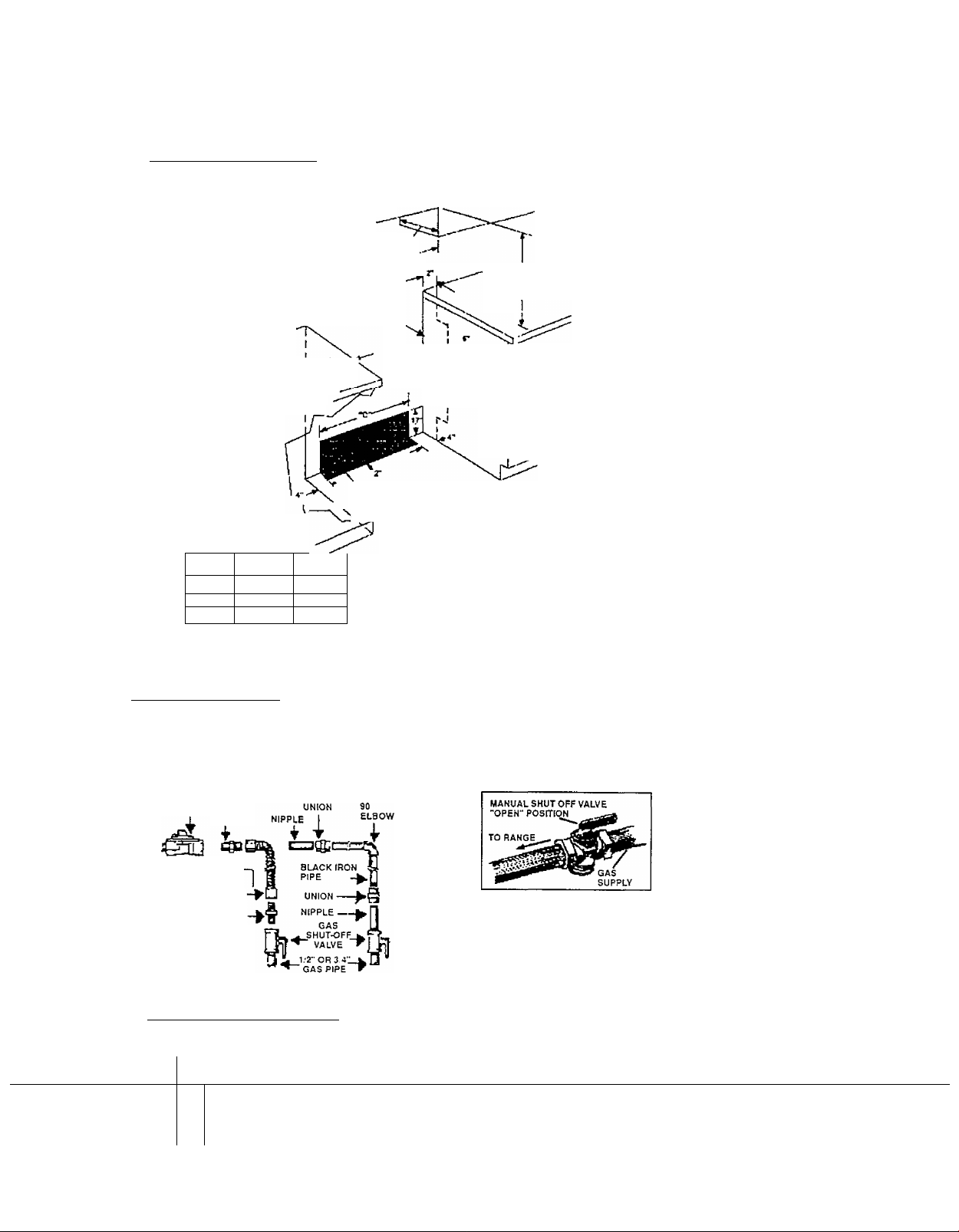
Space Requirements
Ç.9 bi ne [_dime n si on s/requ i re ments
13"max. upper'
cabinet dept
"В"орепПтд
18" min.
clearance upper
cabinet to
countertop
Conbet □ qiKilifled
Пост cmering irublter
b check that the Floor
covering can wilfuland
ol locut 90'F obovo room
temperature
tJie on insulated pad
or l/4‘ p^ood
under range, II installing
range over carpeting.
MODEL
36"
30"
20"
DIM. "A" DIM. "B" DIM. “C"
36"
30" . 30 3/16"
20" 20 1/4"
j^-^width
5" min' '
countertoff'’^
space to side
watt or other
combustible
material
36 3/16” 28 3/16”
"A"niln opening'"^
This shaded area recommended 24" min. when bottom
for installation of ripid qos pipe, metal cabinet is
Jexi^a flos pipe and aiectncoi pfotgeted by not less
22 3/16"
12 1/4"
ouriet ■(,'4" flame retardant
For minimum
clearance to top of
cooktop, see Note
к
¡Contour tino 1er
|bick sMool the
¡modo) 20" r»ngo
Do not pinch the power
supply cord between the
range and the wall
Do not seal the range
to the side cabinets
Oven side panels must
extend beyond cabinet
fronts by 1.'4" where 0”
(flush) of side
walils desired
millboard covered with not
less than N0.28 MSG sheet
steel, 0.015" stainless steel,
0.024" aluminum or 0,020"
copper.
30" min. clearance between
the top of the cooking
platform and the bottom of an
unprotected wood or metal
cabinet.
^ /-Х a
Gas Requirements
TYPICAL CONNECTIONS
FLEXIBLE CONNECTOR HOOK UP RIGID PIPE HOOK UP
PRESSURE
REGULATOR
^*n GAS FLOW
FLEX CONNECTOR-
ADAPTER
ADAPTER
Electrical Requirements
|Т|->к
‘fl
120VOLT, 60HZ, 15 AMP MINIMUM
!
i
i
GAS SHUT OFF VALVE
Page 6
INSTALLATION OF YOUR GAS RANGE
A WARNING
HAVE THIS RANGE INSTALLED BY A QUALIFIED INSTALLER.
Improper installation, adjustment, alteration, services, or
maintenance can cause injury or property damage. Consult a
qualified installer, service agency or the gas supplier.
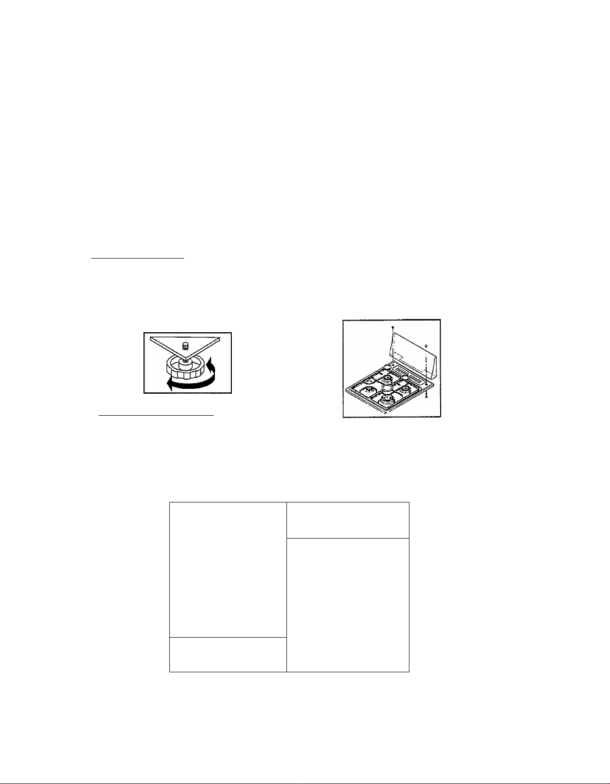
^ Leveling of Range
The range must be level to obtain proper cooking results. The screwed leveling legs located on
the corner brackets at the bottom of range should be adjusted by turning them clockwise to
make the range higher or counter-clockwise to lower the range until the range is level
(See Figure 1). Use a level on the cookware supports to check the leveling of the range.
HIGHER LOWER
Fig. 1
Fig. 2
Backguard Installation
• Place the backguard on top of the cooktop at the rear of the range (Figure 2)
• Line up the holes on the backguard with the holes on cooktop.
• Fasten the backguard to cooktop by using the screws, washers and nuts supplied with
the range.
A
WARNING
- ALL RANGES
CAN TIP
• INJURY TO PERSONS
COULD RESULT
• INSTALL ANTi'TIP
DEVICES PACKED
WITH RANGE
• SEE INSTALLATION
INSTRUCTIONS
Page 7
Anti-Tip Bracket Installation
To reduce the risk of tipping the appliance by abnormal usage
or improper door loading, the appliance must be secured by
properly installing the anti-tip device packed
\with the appliance.
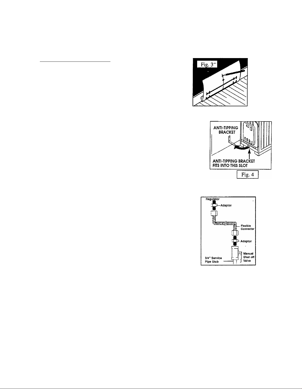
The paper template supplied with the range should be used to
indicate the locations of screws that fix the anti-tip bracket to
adjacent wall.
Fold the paper template along the lower thick black line and
hold it against the floor and wall in the position you intend the range to be
fitted. (See Figure 3). The thick black lines are the same width as the
range.
Mark the centers of the two fixing holes with a pencil on the wall.
If you are fixing to a timber skirting board, make two pilot holes with a
center-punch before screwing the bracket to the wall. If you are fixing to
a plastered/brick/stone wall, use a masonry drill bit and the anchors
supplied.
Finally, screw the anti-tip bracket into the wall and insert the tip of the
bracket to the slot located on the lower rear part of the range
(See Figure 4).
Gas Connection
Gas connection must be made in accordance with local codes
or in absence of local codes, with the National Fuel Gas Code,
ANSI Z223.1-Latest Edition.
Connect gas supply to regulator using a flexible connector, as
shown in Figure 5. Pressure regulator supplied with this range
has a 1/2-inch NPT female connection.
A manual shutoff, not supplied with this range, must be installed
in an accessible location outside of the range.
Use joint compound that is resistant to action of natural or
propane gas on all male pipe threads.
Use supplied pressure regulator only.
Do not over tighten gas fitting when attaching to pressure
regulator. Overtightening may crack regulator.
Appliance and individual shutoff valve must be disconnected from the gas
supply piping system during any pressure testing of that system at test
pressures In excess of 1/2 psi (3.5 kPa).
Appliance must be isolated from gas supply piping system by loosening manual shutoff
valve during any pressure testing of the gas supply piping system at test pressures
equal to or less then 1/2 psi (3.5 kPa).
Gas supply pressure for checking regulator setting must be at least 1-inch water column
above manifold pressure shown on nameplate.
After final gas connection is made, turn on manual gas valve and test all connections in
gas supply piping and range for gas leaks.
Fie. 5
Page 8

In order to avoid property damage or serious personal injury, never use a lighted match.
If a leak is present, tighten joint or unscrew, apply more joint compound, tighten again
and retest connection for leak.
Electrical Connection
• Electrical connection must be made in accordance with local codes or in absence of
local codes, with the National Electrical Code, ANSMNFPA No.70-Latest Edition.
• Connect the 2-prong supply cord to a 120-voIt, 60 Hz, 2-prong wall receptacle.
• Electrical connection must not interfere with gas connection. (See“lnstallation
Requirements" Page 6)
Warning
Improper use of the grounded plug can result in a risk of electrical shock. If the power
cord is damaged have it replaced by an authorized Avanti Products service center.
> Mobile Home Installation
The installation of this range must conform with the Manufactured Home construction and
Safety Standard, Title 24 CFR, Part 3280 {formerly the Federal Standard for Mobile Home
Construction and Safety, Title 24, HUD (Part 280)} or. when such standard is not applicable, the
Standard for Manufactured Home Installations, ANSI A 225.1 and Manufactured Home
Installations, Sites, and Communities ANSI/NFPA 501 A, or with local codes.
When this range is installed in a mobile home, it must be secured to the floor during transit. Any
method of securing the range is adequate as long as it conforms to the standards listed above.
Copies of the standards may be obtained from:
*National Fire Protection Association
Batterymarch Park
Quincy, MA 02269
*American Gas Association
1515 Wilson Blvd.
Arlington, VA 22209
Page 9

OPERATING YOUR GAS RANGE
Before operating the unit, read this section thoroughly. The first time
the burners are operated, a small amount of smoke may be
generated due to burning of grease on the burners, especially on
oven and broiler burners. This is not dangerous. For that reason, it is
advisable to operate the burners without any cooking purpose for 10
minutes. This range is equipped with an electric ignition system to
ignite the burners. Therefore, it must be supplied with electricity.
If any electric power failure occurs, using a match can ignite the burners.
A constant supply of air is needed for combustion. Therefore, allow sufficient
ventilation into the room where the range is placed.
Manual Lighting of the oven burner during power outage
You should place a lighted match next to the entrance of the burner hole.
Depress the oven burner knob and turn counterclockwise.
Keep the control knob depressed for 10 seconds after lighting.
Check that the burner is lit (Figure 7),
> Operation of Surface Burners
There are 3 different types of surface burners with
different size and heat output on the cook top.
* A rapid burner (Front Right)
* Two semi-rapid burners (Back)
* A simmer burner (Front Left)
A WARNING-i
DO NOT ATTEMPT TO OPERATE ANY
SURFACE BURNER WITHOUT INSTALLING
IT. OTHERWISE, THERE IS A RISK OF
EXPLOSION.
First, they must be installed correctly, as seen in Figure 6.
The ring and its cap must be in its place. The burners should be level with the surface of
• The cookware supports must be in place on the cooktop.
These plastic rings are already in place and are used to
prevent rocking as shown in Figure 8.'Extra rings are
supplied for your convenience. Use stable cookware with a
flat bottom and always place the utensil on the cookware
supports before lighting the burner.
• The surface burners are controlled by knobs located on
control panel at front side of the appliance, as seen in
Figure 9.
____________________________________
1
Fiii. 8
Page 10

There is a symbol over the knob on control panel in order to identify which knob
controls which burner. Also, there is a symbol indicator on the knobs, to aid in
setting the burner to the desired temperature.
To Light a Desired Surface Burner
• Push the control knob in.
• After the burner ignites, turn the knob counterclockwise without releasing it to adjust the
flame size. Then release the knob.
• For maximum heat output, align the large flame symbol on the knob with the vertical line
on the control panel. In order to decrease the heat output, turn the knob in the direction of
the small flame symbol. For minimum heat output, align the small flame symbol on the
knob with the vertical line on the control panel.
• The amount of food being cooked, the amount of liquid, or the size of the pan should
determine the heat settings. Always position the utensil on the burner grate before
lighting the burner. For your safety, the flame should not extend beyond the sides of the
pan.
• To turn the burner off, turn the knob clockwise until it reaches the (•) symbol.
The oven is controlled by a knob located at left side of control
panel. (See Figures 9&10)
This knob has two functions.
■ To control oven burner. (GR-20 and DGR-21A)
■ To control broiling burner. (DGR-21A ONLY)
When the knob is turned in a counterclockwise direction, it controls the oven. When the
knob is turned in the clockwise direction, the broiler is engaged. Those burners do not
run simultaneously.
The oven burner is controlled by a thermostat and has a flame failure device. The
numbers on the knob indicate the temperature in the center of oven cavity in degrees of
Fahrenheit.
lO
Page 11

Using Your Oven
• Open oven door to confirm nothing is stored in oven cavity and set racks to proper height.
• Push the oven knob in and turn it counterclockwise to the desired temperature.
• Observe that the oven burner is lit. Wait for ten seconds for the heating of flame failure
device, then release the knob. Never pull up or out the bottom panel of the oven for
observation or operation of oven. Always, make use of slots on the bottom panel of oven
for observation.
• It is usually necessary to preheat the oven. Close the oven door and wait for 10-20
minutes depending on desired temperature, then place food in the oven.
• When selected temperature is reached, the burner will maintain it.
• Do not forget that because the heat rises, the top of the oven will always be hotter than
the bottom.
• After cooking time elapses, remove food and turn oven knob to OFF position, until you
hear a second dick.
> Oven Light f DGR-21A only)
The switch located at the extreme left of the control panel turns the oven light on and off (See
Figure 9). When the button is depressed, the light will be on.
> Clock/Timer fPGR-21A only)
The clock/timer serves two functions: as a clock and as a
cooking timer. It does not control the oven or the cooktop.
You set the timer to remind you of a desired time, at which
a buzzer will sound.
To set the clock (See Figure 11):
• Depress the button located below the TIME display
and turn it to the right until the correct time Is
displayed on the clock.
• Release the button.
To set the cooking time:
• Turn the button located at the left of the TIME display
(do not depress it) until the desired start time of cooking is displayed on the clock.
• Keep in mind that the timer function does not control the oven functions or actual cooking
time. It will alert you when the desired time has passed with a bell.
11
Page 12

Operation of Broiler Burner
The knob controlling the oven burner is also used for operating the
broiler burner. (See Figure 9) When the knob is turned in clockwise
direction, it controls the broiler.
When the knob is'turned in the counter-clockwise direction, the oven
is engaged.
Those burners do not run simultaneously. The broiling burner has
one position. It is full on. The burner can not be set to other heat
outputs.
To operate the broiler burner:
• Open oven door to confirm nothing is stored in oven cavity.
• Place the heat deflector panel, as shown in figure 12.
A WARNINGS
If the heat deflector is not in place, the control panel will
overheat. This could damage the control knobs, and
creates risk of burn injury.
Place food on a cold ungreased broiling pan and set rack to
proper height.
Close the oven door, until it touches the heat deflector panel.
Push the oven knob forward. Ignition starts.
Turn it in the clockwise direction to BROIL position without releasing the knob.
Observe that the broiler burner is lit. Wait ten seconds for the heating of flame
failure device, then release the knob.
Broiling does not require preheating.
All food should be turned at least once.
When the food is cooked enough, remove the food and turn the knob to ‘OFF’ position.
CARE AND MAINTENANCE
The appliance should be cleaned regularly for long-term operation.
Make sure that all parts of the range are cool before cleaning.
> Removing the Oven Door for Cleaning
Open the door fully.
There is a small ring on each hinge. Pull the ring over the claw-like
hook, which is part of the hinge mechanism. Do not forget to do this
on both hinges before the next step. (See Figure 13)
Raise the door slightly and puli it straight outwards away from
the oven. The door will come completely off.
When replacing the door, locate it back into the hinge holes. Pull it
down fully and slip the rings off the claw-like hooks.
Close the door and make sure that it sits in place fully. If not, repeat steps all
above steps.
12
Page 13

> Cleaning your Oven
The oven door glass (DGR-21A) should be cleaned regularly with a non-abrasive liquid cleaner. Rinse
with a damp cloth and then a dry one. The enameled and metal parts of the oven should be cleaned with
hot water and suitable liquid enamel cleaner.
Do not use harsh abrasive cleaners on the enameled panels.
> Cleaning of Knobs and Control Panel
• Pull forward on the knobs to remove them.
• Wash in a water solution with a mild detergent mix. Do not use an abrasive cleaner or abrasive
action. Abrasive action will scratch away the knob markings.
• The control panel should be cleaned by using a damp cloth with mild detergent. Never rinse with
an abrasive cleaner or use abrasive action.
> Cleaning of Utensil Supports, Cooktop, Backquard and Surface Burners
• utensil supports are made of enamel coated steel.
• They can be cleaned at the sink with detergent or soap-filled scouring pads. They can also be put
in a dishwasher.
• The cook top and backguard are also made of enameled-coated steel. They should be cleaned
with hot water and suitable liquid enamel cleaner.
• The aluminum burner rings may be damaged if soaked or put into a dishwasher. They should be
washed with a fine soapy wire wool.
• The burner caps are made of enameled sheet. They can be cleaned in the same manner as
utensil supports. It is very important that the burner be dry before replacing it in the range. A wet
burner will not allow the gas ignite properly.
Converting Gas Type
This range arrives from factory, adjusted for use with Natural Gas. The setting is indicated on
the nameplate. It is important that the range is converted, if the factory adjusted gas type is not
desired.
To avoid electric shock that can cause personal injury or death, disconnect the appliance from
the electric outlet before servicing.
> Conversion of Pressure Regulator
The gas pressure regulator must be set for the type of gas being
used. The inlet pressure of the gas supply shall be in accordance
with the nominal inlet pressure of the regulator used on the range
or 1/2 psi (3.5 kPa) pressure maximum. On the factory setting for
Natural Gas operation, the pressure regulator will regulate the
pressure to 6 inches water column pressure. When set for LP-
Propane gas operation, it will regulate the pressure to 10 inches
water column pressure.
To change the pressure regulator setting:
• Unplug the main supply cord of the range.
' • Unscrew the cap on the pressure regulator.
_________________________
• Lift out cap and turn it over. If set for LP-Propane gas operation, the cap
must show "LP". If set for Natural Gas operation, the cap must show none.
13
Page 14

Conversion of Burner Valves
• Unplug the main supply cord of the range.
• Remove burner control knobs from range by pulling them out.
• Remove the screws on the front surface of control panel.
• Remove two screws located on the bottom surface of control
panel.
• Pull out the control panel.
• Using a small screwdriver, loosen or tighten the screws located
on each valve. If set for LP-Propane gas operation, the screws
must be tightened fully. In the factory setting for Natural Gas
operation, the screws must be loosened by turning them
counterclockwise 3/4 turn.
• Replace the control panel and screws.
• Replace the control knobs. (See Figure 15)
Conversion of Surface Burners
• Unplug the main supply cord of the range.
• Remove the rings of surface burners.
• Pull up the burner rings with their caps and unscrew the orifices
using a 7mm-spanner socket.
• Use orifices located on the information card in a plastic bag at
lower rear side of the range. In order to choose the required orifice
for particular burner and gas type; see the mark located on orifices
and look at the information card.
• Screw each orifice to proper matching burner.
• Place the burner rings to their original locations. Be careful that the
burner rings are level with the surface of the main top.
• Keep the remaining orifices in their plastic bag for future use. (See Figure 16 and
Table 1)
BURNERS
RAPID
SEMl-RAPlD
SIMMER
OVEN
BROILER*
Table 1 - Marks on orifices
1 LP GAS NATURAL GAS
i
0.92
i 0.65 0.97
! 0.50
i 0.90
! 0.90 1.32
1.40
0.75
1.32
•MODEL DGR-21A ONLY
14
Page 15

Conversion of Oven Burner
• Unplug the main supply cord of the range.
• Open oven door.
• Remove the bottom panel of oven pushing it backwards, then lifting
the front edge up and out as shown in Figure 17.
• Loosen the screw which holds the burner in place, and remove the
burner completely (See Figure 18)
• Loosen and remove the orifice at the bottom rear of oven using a
7mm-spanner socket. Replace the orifice supplied with the range.
For the mark of orifice, see Table 1.
• Loosen the retaining screw on the burner ring, if setting for LPPropane gas operation, slide the ring towards the burner to open the
burner hole completely. In the factory setting for Natural Gas
operation, the ring must be located in a place that maintains a gap of
4 mm. (See Figure 19)
• Replace the burner in the oven and replace the screw. Replace the
bottom panel of oven.
• Keep the remaining orifice in its plastic bag for future use.
r^^l]
^
_____
Fig. 17
■1
Conversion of Broiling Burner (Model DGR-21A)
• Unplug the main supply cord of the range.
• Remove the screw and washer holding the burner in place (See
Figure 20).
• Pull out the burner until it releases.
• Remove the orifice using a 7mm-spanner socket. Replace the orifice
supplied with the range. For the mark of orifice, see Table 1.
• Replace the burner and the guard in the oven. Replace the washer
and tighten the screw. Be sure that the burner sits completely in
place while doing this.
• Keep the remaining orifice in its plastic bag for future use.
Fig. 19
Page 16

PROBLEMS WITH YOUR APPLIANCE?
You can solve many common appliance problems easily, saving you the cost of a possible service call.
Try the suggestions below to see if you can solve the problem before calling the servicer.
TROUBLESHOOTING GUIDE
FIND YOUR PROBLEM HERE
POSSIBLE CAUSE
HOW TO FIX IT
Surface burners do not light
Flame burns halfway round.
Surface control has not been
completely turned to the LITE
position.
Burner ports are clogged.
Burners not positioned
properly.
Range not set for appropriate
gas input
Range power cord is
disconnected from the outlet.
Burner ports are clogged.
Moisture is present after
cleaning.
Range is not set for appropriate
gas input
- Push in and turn control to the
LITE position until burner ignites,
then turn control to desired flame
setting.
- Use a small gauge wire or needle
to open parts.
- Verify that the burners are
positioned properly on the orifice
hoods and the burners are sitting
flat on the burner support with tabs
engaged in slots.
- See range conversion section of
this manual.
- Be sure power cord is plugged
into grounded outlet.
Use a small gauge wire or
needle to open ports.
Lightly fan the flame and allow
burner to operate until flame is
full, or dry burners thoroughly
following instructions in range
"Cleaning” section.
See range conversion section
of this manual.
Flame is orange.
Oven light does not work.
Dust particles in main line.
Range is not set for
appropriate gas input
Burned out or loose bulb.
16
- Allow burner to operate for a
few minutes until flame turns blue.
- See range conversion section of
this manual.
- Tighten or replace oven light
bulb. (DGR-21Aonly)
Page 17

Oven or broiler does not heat.
Range is not set for
appropriate gas input.
Temperature control not set
properly.
Flame safety device does not
allow the gas flow
Range cord is disconnected
from outlet
-See range conversion section of
this manual.
-Make sure temperature control is
set at desired temperature.
-Push forward the control knob fully
for ten seconds. If the burner lights
on and does not maintain it, the
thermocouples must be cleaned.
-Be sure the power cord is plugged
into a grounded outlet.
Oven temperature is inaccurate.
Oven capillary bulb not
positioned properly.
- Temperature control not set
properly.
Improper use of foil.
Vent blocked.
Range not set for appropriate
gas input
Smoke or odor on initial oven
-This is normal.
operation.
Range is not level.
- Poor installation.
- Weak or unstable floor.
Kitchen cabinet misalignment
may make range appear to be
unlevel.
Oven smokes excessively. Meat too close to broiler
burner.
Meat not prepared properly.
-Verify that capillary bulb is
snapped in clips straight and not
touching sides or coated with oven
cleaner or food.
-Make sure the temperature control
knob is set at the desired
temperature.
-Keep foil clear of holes in oven
bottom and off of oven racks.
-Keep vent at front of backguard
clear.
-See range conversion section in
this manual.
Place oven rack in center of
oven. Place a level on the
rack. Adjust leveling legs.
Be sure floor is level and can
adequately support range.
Contact carpenter to correct
sagging or sloping floor.
Be sure cabinets are square
and have sufficient room for
range clearance. Contact
cabinetmaker to correct
problem.
Reposition the broiler pan to
provide more clearance
between the meat and the
broiler burner. (See "Operation
of Broiler")
Remove excess fat from meat.
Nuisance sparking while oven is in
operation
Oven burner cycles high and low
Improperly grounded or
reversed polarity electrical
outlet
This is normal
17
Have outlet corrected by a
qualified electrician
Page 18

SERVICE FOR YOUR GAS RANGE
We are proud of our customer service organization and the network of professional service
technicians that provide service on your Avanti appliances. With the purchase of your Avanti
appliance, you can have the confidence that if you ever need additional information or
assistance, the Avanti Products Customer Service team will be here for you. Just call us tollfree.
AVANTI PRODUCTS CUSTOMER SERVICES
Product Information
800-323-5029
Part Orders
800-220-5570
In-Home Repair Service
800-220-5570
Whatever your questions are about our
products, help is available.
You may order parts and accessories that
will be delivered directly to your home.
You may order these items by personal
check, money order, Master Card, or Visa.
An Avanti Products authorized service
center will provide expert repair service,
scheduled at a time that is convenient for
you. Our trained Servicers know your
appliance inside and out.
18
Page 19

WARRANTY - GAS RANGE
LENGTH OF WARRANTY
FULL ONE-YEAR WARRANTY FROM
DATE OF PURCHASE ON ALL PARTS
EXCEPT GLASS PARTS
FULL 30-DAY WARRANTY FROM DATE
OF PURCHASE ON GLASS PARTS AND
FINISH OF PORCELAIN ENAMEL,
PAINTED OR BRIGHT METAL FINISHED
PARTS
WE WILL NOT PAY FOR
A. Service calls to:
1. Correct the installation of your range.
2. Instruct you how to use your range.
3. Replace house fuses or correct house wiring.
4. Replace owner-accessible light'bulbs.
B. Pickup and delivery. Your range is designed to be repaired in the home.
C. Damage to your range caused by accident, misuse, fire, flood, acts of God, or use of products not
mentioned in this manual.
D. Repairs to parts or systems caused as a result of unauthorized modifications made to the
appliance.
E. Repairs when your range is used in other than normal, single-family household use.
"we will PAY FOR
REPLACEMENT PARTS AND REPAIR
LABOR TO CORRECT DEFECTS IN
MATERIALS OR WORKMANSHIP.
SERVICE MUST BE PROVIDED BY AN
AUTHORIZED SERVICE COMPANY.
REPLACEMENT PARTS AND REPAIR
UBOR TO CORRECT DEFECTS IN
MATERIAL OR WORKMANSHIP. SERVICE
MUST BE PROVIDED BY AN AUTHORIZED
SERVICE COMPANY.
AVANTI PRODUCTS SHALL NOT BE LIABLE FOR INCIDENTAL OR CONSEQUENTIAL
DAMAGES.
Some states do not allow the exclusion or limitation of incidental or consequential damages, so
this exclusion or limitation may not apply to you. This warranty gives you specific legal rights,
and you may also have other rights that vary from state to state.
This warranty is not valid outside the United States.
19
Page 20

Warranty Information
Thank you for purchasing this fine Avanti product. Please fill out this card and return it within
100 days of purchase and receive these
important benefits:
> Confirm your warranty:
Your prompt product registration confirms your right to the protection available under the
terms and conditions of your Avanti warranty.
> Protect your product:
We will keep the mode! number and date of purchase of your new Avanti product on file
to help you refer to this information in the event of an insurance claim such as fire or
theft.
> Promote better products:
We value your input. Your responses will help us develop products designed to best
meet your future needs.
“(detach here)-
Avanti Registration Card
Name Model #
Address
City
State
Zip
Date Purchased
Occupation
Area Code Phone Number
Did You Purchase An Additional Warranty:
□Extended GNone
Reason For Choosing This Avanti Product:
Please indicate the most important factors
that influenced your decision to purchase
this product.
□Price
□Product Features
□Avanti Reputation
□Product Quality
□Salesperson Recommendation
□Friend/Relative Recommendation
□Warranty
□Other
Serial #
/
Store/Dealer Name
As Your Primary Residence. Do You:
□Own GRent
Your Age:
□ under 18 118-25 □26-30
□ 31-35 136-50 Gover 50
Marital Status:
□Married “Single
Is This Product Used In The:
□Home OBusiness
How Did You Learn About This Product:
□Advertising
□ In Store Demo
□Other
_______
□Product Features
□ Personal Demo
Comments
20
Page 21

HELP US HELP YOU...
Read this guide carefully.
It is intended to help you operate and
maintain your new gas range properly.
Keep it handy to answer your questions.
If you don't understand something or you
need more help, please call:
Avanti Customer Service
800-220-5570
Keep proof of original purchase date (such
as your sales slip or cancelled check) with
this guide to establish the warranty period.
Write down the model and serial
numbers.
You’lLJpd them on a plate located on the left
wall inside the gas range.
Please write these numbers here:
Date of Purchase
Model Number
Serial Number
Use these numbers in any correspondence
or service calls concerning your gas range.
If you received a damaged gas range,
immediately contact the dealer (or builder)
that sold you the gas range.
IF YOU NEED SERVICE
We're proud of our service and want you to
be pleased. If for some reason you are not
happy with the service you receive, here are
some steps to follow for further help.
FIRST, contact the people who serviced
your appliance. Explain why you are not
pleased. In most cases, this will solve the
problem.
Save time and money. Before you call for
service, check the Problem Solver Guide. It
lists causes of minor operating problems
that you can correct yourself.
NEXT, if you are still not pleased, write all
the details, including your telephone
number, to:
Customer Service
Avanti Products
10880 NW 30 Street
Miami, FL 33172
21
Page 22

Parts and Features
DGR-21A
Parts and Feature
FOUR SEALED BURNERS
THREE TYPES :
A RAPID BURNER
TWO SEHI-RAPID
BURNERS
A SIMMER BURNER
DUAL PORCELAIN
ENAMEL COOK TOP
FULL CONTROL
PANEL FOR EASE OF
OPERATION
OVEN TEMPERATURE
CONTROL DIAL
GR-20
Parts and Feature
-jBACKGUARPl
SURFACE BURNER
MARKER TO
INDICATE INDIVIDUAL
BURNER SETTING
AUTOMATIC
ELECTRONIC IGNITION
DUAL PORCELAIN
ENAMEL OVEN DOOR
22
Page 23

Wiring Diagrams
MODEL DGR-21A
MODEL GR-20
23
 Loading...