

Page 1

INSTRUCTION MANUAL
MANUAL DE INSTRUCCIONES
Model Number/ No. de Modelo; BD555
BEER DISPENSER
(DISPENSADOR/ENFRIADOR DE CERVEZA)
CAUTION:
BEFORE USE, PLEASE READ AND FOLLOW ALL SAFETY RULES AND OPERATING
INSTRUCTIONS.
La sección en español empieza en la página 20.
Avanti has a policy of continuous improvement on its products and reserves the right to change
materials and specifications without notice.
Avanti Products, A Division of The Mackle Co., Inc.
---------
P.O. Box 520601 ■ Miami, Florida 331.52
www.avantiproducts.com
--------
Page 2

ORDER FORM
Avanti Products, P.O. Box 520604, Miami Florida 33152
For your convenience, you may use a major credit card (Master Card, or Visa) to order accessories over the phone by calling (800) 220-5570.
To order by mail, please fill out the following form and send it in with your payment (check, money order or credit card) using the above address.
NAME (please print)
ADDRESS
Qty
Item
SH-1
CS-2
Description
2 SHELVES
2 CASTERS 9.95
SHIPPING AND HANDLING
Price
SUBTOTAL
ACCESSORIES SUBJECT TO AVAILABILITY
PLEASE MAKE CHECKS PAYABLE TO: AVANTI PRODUCTS
Avanti has a policy of continuous improvement on its products and reserves the right to change materials and specifications without notice.
9.95
TOTAL
Total
$ 6.25
$
CITY
STATE
DAYTIME PHONE ( )____
ENCLOSED IS $
IJcHECK pMONEY ORDER [JmASTER CARD []viSA
CREDIT CARD NUMBER
EXPIRATION DATE
NAME (AS IT APPEARS ON CREDIT CARD)
SIGNATURE
(OF CREDIT CARD HOLDER)
ZIP
Page 3
Registration Information
Thank you for purchasing this fine Avanti product. Please fili out this card and return it within 100
days of purchase and receive these
important benefits:
Protect your product:
We will keep the model number and date of purchase of your new Avanti product on file to
help you refer to this information in the event of an insurance claim such as fire or theft.
Promote better products:
We value your input. Your responses will help us develop products designed to best meet
your future needs.
—-
.......
(Detach Here)--
Avanti Registration Card
.......
Name
Address Date Purchased Store/Dealer Name
City
Area Code
Did You Purchase An Additional Warranty:
□ Extended □Food Loss GNone
Reason For Choosing This Avanti Product:
Please Indicate the most important factors
that influenced your decision to purchase
this product.
Q Price
G Product Features
QAvanti Reputation
Q Product Quality
□ Salesperson Recommendation
□ Friend/Relative Recommendation
□Warranty
□Other
_______________________
State
Phone Number
Zip
Model #
Occupation
As Your Primary Residence. Do You:
□Own GRent
Your Age:
□ under 18 □18-25 G26-30
□31-35 □36-50 Dover 50
Marital Status:
□ Married DSingle
Is This Product Used in The:
□Home DBusiness
How Did You Learn About This Product:
□Advertising □ Product Features
□ In Store Demo □ Personal Demo
□Other
______________________________
Comments
_________
Serial #
Page 4
HELP US HELP YOU...
Read this guide carefully.
It is intended to help you operate and maintain
your new Beer Dispenser properly.
Keep it handy to answer your questions,
if you don't understand something or you need
more help, please call:
Avanti Customer Service
800-220-5570
Keep proof of original purchase date (such as
your sales slip) with this guide to establish the
warranty period.
CAUTION:
THIS BEER DISPENSER IS NOT
DESIGNED FOR THE STORAGE
OF MEDICINE OR OTHER
MEDICAL PRODUCTS.
Write down the model and serial numbers.
You'll find them on a plate located on the
bottom outside wall of the Beer Dispenser.
Please write these numbers here:
Date of Purchase
Model Number
Serial Number
Use these numbers in any correspondence or
service calls concerning your Beer Dispenser.
If you received a damaged Beer Dispenser,
immediately contact the dealer (or builder) that
sold you the Beer Dispenser.
Save time and money. Before you call for
service, check the Troubleshooting Guide. It
lists causes of minor operating problems that
you can correct yourself.
IF YOU NEED SERVICE
We're proud of our service and want you to be
pleased. If for some reason you are not happy
with the service you receive, here are some
steps to follow for further help.
FIRST, contact the people who serviced your
Beer Dispenser. Explain why you are not
pleased, in most cases, this will solve the
problem.
NEXT, if you are still not pleased, write all the
details, including your telephone number, and
send to:
Customer Service
Avanti Products
10880 NW 30 Street
Miami, FL 33172
Page 5

Table of Contents
Warranty Information and Registration Card,
Help Us Help You___________________________
Parts and Features
Important Safety Instructions,
Installation Instructions
Before Using Your Beer Dispenser_
Installation of Your Beer Dispenser,
Electrical Connection
Installation of C02
Dispensing of Beer
Converting to an All Refrigerator,
Operating Your Beer Dispenser_
Temperature Control
Care and Maintenance
Automatic Defrosting
Changing the Reversible Door_
Cleaning Your Beer Dispenser,
Maintenance of Your Beer Dispenser,
Vacation Time
Moving Your Beer Dispenser,
Draught Beer Trouble Guide_
Troubleshooting Guide
Service For Your Beer Dispenser,
Wiring Diagram
Your Avanti Products Warranty,
SPANISH VERSION
_______________________
__________________
________
_______________
__________________
_______________
_____________
____________
_____________
________
_____________
,8-9
JO
JO
J1
J1
J1
_11
J2
J2
J2
J2
12
.13-16
__
17
___
18
___
18
19
20-30
Page 6
PARTS AND FEATURES
1 Beer Tower
2 Safety Guard Rail
3 Adjustable Thermostat
4 CO2 Gas Can
5 CO2 Regulator
6 Reversible Door
7 Beer Keg (not Included)
8 Beer Keg Stand
9 Leveling Legs
10 Metal Plate
Page 7

Important Safety Instructions
yWARNINOy
Read all instructions before using the refrigerator.
To reduce the risk of fire, electrical shock,
or injury when using your Beer Dispenser,
follow these basic precautions:
_____________
DANGER or WARNING: Risk of child entrapment.
Before you throw away your old refrigerator or freezer: Take off the doors.
Leave the shelves in place so that children may not easily climb inside.
Never allow children to operate, play with, or crawl inside the refrigerator.
Never clean refrigerator parts with flammable fluids. The fumes can create a fire
hazard or explosion.
Do not store or use gasoline or any other flammable vapors and liquids in the vicinity
of this or any other refrigerator. The fumes can create a fire hazard or explosion.
-Save these instructions-
INSTALLATION INSTRUCTIONS
Before Using Your Beer Dispenser
• Remove the exterior and interior packing.
• Check to be sure you have all of the following parts:
Instruction manual
Instruction video
1 Safety Guard Rail
1 Drip Tray (2 Pieces)
1 Cylinder Support
1 C02 Regulator (Box)
1 COa Empty Cylinder (Box)
1 CO2 Air Line Hose (Red)
2 CO2 Hose Connectors
1 Beer Keg Coupler (Box)
1 Beer Tower
1 Pull Handle (Beer Tower Faucet)
1 Spanner Faucet Wrench (see illustration on page 10)
6 Plugs (Guard Rail)
1 Beer Keg Stand
1 Metal Plate For Cabinet Bottom
• Before connecting the Beer Dispenser to the power source, let it stand upright for
approximately 2 hours. This will reduce the possibility of a malfunction in the cooling system
from handling during transportation.
• Clean the interior surface with lukewarm water using a soft cloth.
Installation of Your Beer Dispenser
• This appliance is designed to be free standing only, and should not be recessed or built-in.
• Place your Beer Dispenser on a floor that is strong enough to support the Beer Dispenser
when it is fully loaded.
• Allow 3 inches of space between the back and sides of the Beer Dispenser, which allows the
proper air circulation to cool the compressor.
• Locate the Beer Dispenser away from direct sunlight and sources of heat (stove, heater,
radiator, etc.). Direct sunlight may affect the acrylic coating and heat sources may Increase
------
electrical consumption. Extreme cold ambient temperatures may also cause the Beer
Page 8

Dispenser not to perform properly.
Avoid locating the Beer Dispenser in moist areas.
After plugging the appliance into a wail outlet, allow the unit to cool down for 2-3 hours before
placing any contents in the Beer Dispenser compartment.
Electrical Connection
X Warning V
Improper use of the grounded plug can result in the risk of electrical shock, if the power cord is
damaged, have it replaced by an authorized Avanti Products service center.
This appliance should be properly grounded for your safety. The power cord of this appliance is
equipped with a three-prong plug which mates with standard three prong wall outlets to minimize
the possibility of electrical shock.
Do not under any circumstances cut or remove the third ground prong from the power cord
supplied.
Plug the appliance into an exclusive properly installed-grounded wall outlet. Do not under any
circumstances cut or remove the third (ground) prong from the power cord. Any questions
concerning power and or grounding should be directed toward a certified electrician or an
authorized Avanti Products service center.
Use of extension cords is not recommended.
This appliance requires a standard 115/120-volt, 60Hz electrical outlet with three-prong ground.
The cord should be secured behind the appliance and not let exposed or dangling to prevent
accidental injury.
Do not use an extension cord with this appliance. If the power cord is too short, have a qualified
electrician or service technician install an outlet near the appliance.
Warning
CO2 GAS CAN BE DANGEROUS
WARNING: CO2 cylinders contain high-pressure compressed gas which can be hazardous if not
handled property. Make sure you READ and UNDERSTAND the following procedures for CO2
cylinders BEFORE INSTALLATION.
1. ALWAYS connect the CO2 cylinder to a regulator. Failure to do so could result in explosion
with possible death or injury when the cylinder valve is opened.
2. NEVER connect the C02 cylinder directly to the product container.
3. ALWAYS follow correct procedures when cylinders are changed.
4. ALWAYS secure the cylinder in an upright position.
5. NEVER drop or throw a C02 cylinder.
6. ALWAYS keep a CO2 cylinder away from heat. Store extra cylinders in a cool place
(preferably TO^F). Securely fasten with a chain in an upright position when storing.
7. ALWAYS ventilate and leave the area immediately if CO2 leakage has occurred.
8. ALWAYS check the D.O.T. test date on the cylinder neck before installation. If over five (5)
years, do not use, return cylinder to gas supplier.
9. NEVER connect a product container unless there are two (2) safety’s in the pressure system:
a. One at or on the CO2 regulator
b. One at or on the product coupler or in the pressure gas line.
Page 9
INSTALLATION INSTRUCTIONS
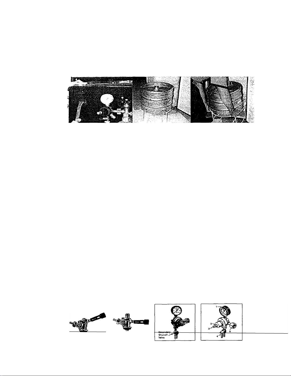
Installation Of CO2 Cylinder Support
• Install the metal support provided onto the 4 studs located on the exterior back wall. Align the
holes in the support with the studs and push down firmly. {See Figure 1)
Installation Of CO2 Cylinder
• Install your fully charged cylinder into the support stand.
installation Of CO2 Regulator
• Attach the CO2 regulator to the cylinder by turning the regulator nut onto cylinder valve,
making sure washer is securely inserted into connecting nut. Tighten snug using an
adjustable wrench and assure there are no leaks. (See Figure 2)
Installation Of CO2 Air Line Hose To Regulator
• Attach one end of the air line (red) hose provided to the hose connection on the regulator.
• Secure hose by using one of the two clamps provided. Use pliers to tighten clamp and assure
no teaks. (See Figure 3)
Installation Of CO2 Air Line Inside Cabinet
• Remove plug located at the exterior back (top left hand corner).
• Save it for later use if you decide to convert unit to an ail refrigerator.
• Insert the open end of the air line (red) into the cabinet through the uncovered hole. (See Figure 4)
Installation Of The Beer Tower
• Remove the top plug by twisting and puliing out, saving it for later use if you decide to convert unit
to an all refrigerator.
• Unravel the beer line (hose) from the tower and insert the beer line and wing nut through the
uncovered hole on top.
• Lock the beer tower assembly to the top and make sure to position the beer faucet so it is aligned
with the cabinet front (6 o’clock position). You accomplish this by aligning the bottom of the beer
tower to the 3 grooves on the top cabinet and tighten by hand clockwise to properly lock.
• Plastic faucet lever: see explanation and skectch on page 10.
Installation Of Protective Metal Plate
• This plate should always be installed when the keg stand is in place to protect against
unnecessary damage to the floor of the cabinet.
Fi« 1
Fig. 2
Fig.3
Page 10
Installation Of The Beer Keg
• Position the keg stand directly in front of the open door. Using keg handles only, carefully lift the
beer keg onto the stand. (See Figure 5)
• To place the beer keg and stand inside the cabinet, brace your knees behind the keg stand. Lift
the front of the keg just enough so the front edge of the stand is resting on the front edge of the
Beer Dispenser bottom cabinet. (See Figure 6)
- Grasp the keg stand front handles and slide it all the way into the cabinet.
Fig. 4
Fig. 5 Fig. 6
Installation Of The Keg Coupler
• Insert the keg coupler provided into the locking neck of the beer keg and turn it clockwise to lock
into position, making sure the keg coupler is in the closed position. (See Figure 7)
Installation Of The CO2 Air Line Hose
• Attach the open end of the red hose to the hose barb connection on the keg coupler. Secure hose
by using the plastic snap provided, using pliers to tighten clamp.
Connecting the beer tower to coupler
• Make sure the washer is properly inserted into the wing nut.
• Place wing nut into the top of the coupler turning until tight.
How To Tap A Keg Of Beer
• Make sure the beer tower faucet is in the closed position.
• Pull tapping handle out and press downward until it locks into position. (See Figure 8) The keg is
now tapped.
Opening The CO2 Cylinder Main Valve
• Before doing that, make sure the secondary shut-off valve is closed, as shown in figure 9. To
open the main CO2 cylinder valve, slowly turn the main valve counter-clockwise until fully open.
• Notice the needle on the gauge start to climb.
Adjusting The CO2 Regulator
• The gauge monitors low internal keg pressure and should be adjusted to read between 10-12
psi/lbs. (See Figure 10)
• In order to do that:
1. Release adjustment lock nut marked 2.
Using a flat screwdriver, turn regulator screw marked 3. If increased low pressure is sought,
2.
rotate screw clockwise. By rotating it counter clockwise, low pressure will be decreased when
the required operating pressure is attained, retlghten lock nut 2.
Open secondary shut off valve to let C02 flow into the keg.
3.
Fig 7
F,g 8
Fig 3
Fig 10
Page 11

Spanner Faucet Wrench
Spanner faucet wrench provided for either removing or tightening
connection.
Plastic Faucet Lever
Attach the black plastic lever (pull handle) provided on top of the faucet
by tighten it by hand clockwise until the end, holding in the process the
golden snug underneath so it does not move.
If there is still a small drip from the faucet, you may have tightened the
plastic lever too much and may need to unscrew golden snug counter
clockwise (as shown) one turn. That should Correct the problem if exists.
Dispensing Beer:
• Keep beer keg refrigerated at all times.
• Never allow beer lines to dry out.
• Use clean beer glassware before pouring.
• Hold glass at a 45° angle when 2/3 full, start to straighten glass and tap it off,
• Always make sure the faucet handle is pushed all the way back.
• A beer faucet lock is available so access to the consumption of beer can be limited to people
above the legal age.
Note: Keg sizes that can be used in your beer dispenser
1/4 barrel 30 Liters 7.8 gals. 992 oz. 82/12-oz. Glass
1/6 barrel 20 Liters 5.2 gals. 661 oz. 55/12-oz. Glass
1/8 barrel 15 Liters 4.0 gals. 496 oz. 41/12-oz. Glass
Converting Your Beer Dispenser To An "Alt Refrigerator”.
I. Turn off the control knob to the “OFF’ position.
Close the main valve on the C02 cylinder.
Close the secondary shut-off valve on the regulator pipe.
Close the connection between the beer keg and the keg coupler.
Drain any remaining beer from the lines.
Disconnect the beer line and C02 air line from the keg coupler
Remove the beer keg, keg stand and bottom metal plate from the cabinet.
Remove the keg coupler.
Disconnect the air line from the CO2 cylinder.
10. Remove the CO2 air line from cabinet plug
II. Replace the air line rear cabinet plug
12. Remove the beer tower. Also pull the beer line thru the top of the cabinet
13. Replace the top cabinet plug
14. Order the optional wire shelves and install them on the side supports.
15. Adjust temperature as desired.
10
Page 12

OPERATING YOUR BEER DISPENSER
> Setting The Temperature
To start, turn the temperature control knob to the maximum setting to achieve fastest cooling
quickly. Allow the unit to run for 3 hours. Temperature range of the thermostat goes from
36°F to 45°F.
Optimum temperature for serving draught beer is between 34®F - SS^F and that is a key
factor to consider in storing and dispensing draught beer.
To turn off the Beer Dispenser, rotate the control knob to the “OFF’ position.
Note; Keep an accurate thermometer handy and adjust temperature control setting as
necessary or according to your needs.
Automatic defrosting
There is no need to defrost the Beer Dispenser. Defrost water collects and passes thru the
drain outlet in the rear wall into a tray located above the compressor, where it evaporates.
NOTE:
« If the unit is unplugged, power lost, or turned off; you must wait 3 to 5 minutes before
restarting the unit, if you attempt to restart before this time delay, the Beer Dispenser will
not start.
CARE AND MAINTENANCE
> Reversal And installation Of the Beer Dispenser Door
This Beer Dispenser has the capability of either opening the door from the left or right side. The unit is
delivered to you with the door opening from the left side. Should you desire to reverse the opening
direction, please follow these instructions.
NOTE:
All parts removed must be saved to do the reinstallation of the door.
Remove both screw-type leveling legs (7).
Remove the three screws (8) that hold the lower right hinge (4), save hinge for later use.
Remove door from upper pin (1), lift it and place it on a padded surface to prevent scratching
it.
Using a flat screwdriver remove right upper pin and transfer it to the same location on the
opposite side.
Remove the pin cap (2) from the left side of the upper frame of the door, and then transfer it
to the same location on the opposite side.
Remove inner plug (3) from upper frame of door and transfer it to the uncovered hole on the
opposite side.
Insert lower hinge (4) previously saved to the lower left side of the door. Before placing this
hinge, reverse the direction of the bolt-pin (6).
Set the door in place making sure the pin enters the bushing at the uncovered hole on the
upper frame of the door.
While holding the door tn me closed position, secure the lower leimtngsijytlgiTternirig ail the
screws, making sure the door is leveled with the countertop.
11
Page 13

FIGURE 1 (Position prior to door reversal) FIGURE 2 (Position after door reversal)
1 Upper Pin
2 Pin Cap
3 Inner Plug
4 Lower Door Hinge
5 Washer
6 Bolt-pin
7 Leveling Legs
8 Door Hinge Screws
Cleaning Your Beer Dispenser
• Turn the temperature control to "OFF", unplug the Beer Dispenser, and remove the contents.
• Wash the inside surfaces with a warm water and baking soda solution. The solution should be
about 2 tablespoons of baking soda to a quart of water.
• Wash the shelves and stand with a mild detergent solution.
• The outside of the Beer Dispenser should be cleaned with mild detergent and warm water.
• Wring excess water out of the sponge or cloth when cleaning area of the controls, or any
electrical parts. ■
• Wash the outside cabinet with warm water and mild liquid detergent. Rinse well and wipe dry
with a clean soft cloth.
Vacation Time
Short vacations: Leave the Beer Dispenser operating during vacations of less than three weeks.
Long vacations: If the appliance will not be used for several months, remove all contents and
unplug the power cord. Clean and dry the interior thoroughly. To prevent odor and mold growth,
leave the door open slightly; blocking it open if necessary.
Moving Your Beer Dispenser
Remove all the contents.
Securely tape down all loose items inside your Beer Dispenser.
Turn the leveling screws up to the base to avoid damage.
Tape the door shut.
Be sure the Beer Dispenser stays secure in the upright position during transportation. Also
protect outside of Beer Dispenser with a blanket, or similar item.
12
Page 14

CLOUDY BEER
When beer in glass appears hazy, and not clear.
Causes
1)
♦ Over chilling beverage cooler and/or
beverage lines.
2)
• Cracking, or when partially opening beer
faucet.
3)
• General conditions causing cioudy beer.
May taste and smell extremely yeasty, or moldy.
Cause
1)
• Contaminated Air Line.
Corrections
1)
• Excessive low temperatures may cause hazy,
cloudy beer, particularly when beer lies in cold
coil for long periods of time. Make certain that
lines are thoroughly cleaned, and then raise
temperature slightly.
2)
• Open faucet quickly and completely.
• Replace worn washers and parts in faucet
when necessary to permit full opening of
faucet.
3)
• See wild beer corrections #2 and #6,
SOUR BEER
Corrections
1)
• See Off-Taste Beer, Correction #2
2)
• Improper transportation of barrels of
beer, Beer delivered on open truck,
during high summer temperatures, may
be the cause for starting secondary
fermentation.
3)
• No refrigeration, and improper rotation.
2)
• If at all possible, deliver beer barrels in closed
body, refrigerated truck. If open staked body
truck is used, cover barrels with a tarpaulin for
protection against summer heat, and
circulating warm air.
• Truck should never be loaded the night before
morning delivery, unless beer is refrigerated In
truck.
3)
• The rule is first barrel in, first tapped.
• Refrigeration must be left on winter or
summer.
• Sour beer is generated as a result of
secondary fermentation, above 45° F degrees.
Retail outlets that do not have refrigeration
should ice up barrels, or at least cover barrels
with tarpaulin or burlap bags.
• Best temperature for barrels is 38° to 40° F.
13
Page 15

FLAT BEER
Foamy head disappears quickly: beer iacks usual zestful brewery fresh flavor.
Causes Corrections
1)
Greasy glass
2)
improper drawing of beer into glass.
1)
Do not wash beer glasses together with
glasses that have contained milk or any
other fatty substance. Lipstick is a fatty
substance. Make sure it is removed from
glass.
Excess amount of germicides build up and
leave a fatty film on glass, which may cause
flat beer.
It is preferable to steam and sterilize
glasses where health laws permit.
Wash glasses thoroughly with a good
detergent.
Do not use soap.
Do not dry-wipe glasses. Permit glasses to
air-dry by placing them on wire or
corrugated metal.
Rinse in fresh cold water just before serving
beer. It is best to serve beer In a wet glass.
2)
Open faucet quickly and completely.
Check and find the correct distance to hold
glass from faucet when drawing. Proper
foam should be a tight creamy head, and
the collar on the average glass should be W
to 1” high.
Beer drawn without head has appearance of
being flat.
3)
Not enough pressure.
4)
Sluggish pressure regulators.
Causes
Large soap-like bubbles (sometimes
called fish eyes). Foam settles quickly.
3)
Increase pressure if beer runs too slowly.
4)
A regular seat, or the regulator diaphragm,
may require replacing.
LOOSE FOAM
Corrections
• This is generally a Flat Beer condition: the
Causes and corrections for Fiat Beer should
be followed.
14
Page 16

OFF-TASTE BEER
Often bitter and bitey, sometimes completely odor, carrying an unpleasant taste.
Beer lines should be flushed after each barrel is empty. Maintain fresh, Clean, sanitary
conditions at bar. Smoke, kitchen odors, fly sprays, and disinfectants will harm the tast and
flavor of beer, making it unpalatable. These conditions, as described, may come from an air
source, or from actual contact with the glass at bar.
Causes
1)
• Improper, hose, leads, and direct draw
system.
2)
• Contaminated Air Line.
3)
• Rubber hose will absorb and retain
odors.
Corrections
1)
• Brush and clean faucet, (see Wild Beer,
Correction #2)
• Taps, rods, and tap-Seal fitting should ail be
scoured, using a detergent, then rinsed clean.
• Direct draw Systems must be cleaned the
same as coil systems; 4 feet of direct draw
line accumulates as much per foot as any
other system.
2)
• Air hoses, air lines should be examined, and if
contaminated, replaced.
• Dirty air lines should be washed with a good
cleaning compound and then rinsed clean.
3)
• Rubber hose will absorb and retain odors. An
approved Vinyl tubing is best for air since it
does not absorb moisture, and is not affected
by oily substances.
• A fresh, outdoor, air line is imperative when air
is the source of pressure.
-
15
I
:#■
Page 17

WILD BEER
Beer, when drawn, is afi foam, or too much foam, and not enough liquid beer.
Cause
1)
* Improper drawing beer into glass.
2)
• Yeast growth, or other obstructions in
faucet.
* Worn faucet parts and worn faucet
washers.
3)
• Kinks, dents, or twists in coils, or direct
draw lines: obstructions in line, near, or
behind faucet.
4)
* Sag, or trap in line.
5)
• Too much air pressure.
Corrections
1)
• Open faucet quickly and completely.
• Check and find the correct distance to hold
glass from faucet when drawing. Proper foam
should be a tight, creamy head, and the collar
on the average glass should be % " to 1" high.
2)
• Clean faucet spout with a good brush daily.
Scour all internal faucet parts at least once a
week.
• Replace worn washers as required, if faucet
does not open wide, worn parts or entire
faucet must be replaced.
3)
• Check for, and replace kinked, dented, or
twisted line from barrel to faucet.
• Examine for frayed coupling washer behind
faucet that may cause obstruction.
4)
• Keep all metal beer lines straight from barrel
to faucet: never permit lines to sag, as this
creates traps that may cause wild beer.
5)
• Check source of pressure. Adjust pressure to
suit properly balanced system. For correct
beer flow, fill a 10 02. Glass in 4 seconds at
proper temperature.
• Check and replace a creeping regulator and
gauge.
6)
• Excess CO2.
I
7)
• Not enough pressure.
• No pressure.
I
6)
• Adjust pressure when using CO2 as low as
possible, however, remembering that the
applied pressure must be slightly higher than
the internal pressure of the beer (no more
than 18 lbs. Should be applied.)
• The colder the beer and the higher the applied
CO2 pressure, the more rapid the absorption
of CO2 by the beer. This over-carbonates the
beer, causing Wild Beer.
7)
• Check for defective air vents, {see Flat Beer,
Corrections #3)
• Always turn pressure on before drawing beer.
16
Page 18

PROBLEMS WITH YOUR BEER DISPENSER?
You can solve many common Beer Dispenser problems easily, saving you the cost of a possible
service call. Try the suggestions below to see if you can solve the problem before calling the servicer.
TROUBLESHOOTING GUIDE
PROBLEM
Beer Dispenser does not operate.
Turns on and off frequently.
Vibrations.
The Beer Dispenser seems to make too much
noise.
The door will not close properly.
Not plugged in.
The circuit breaker tripped or blown fuse.
The room temperature is hotter than normal.
The door is open too often.
The door is not closed completely.
The temperature control is not set correctly.
The door gasket does not seal properly.
The Beer Dispenser does not have the correct
clearances.
Check to assure that the Beer Dispenser is level.
The rattling noise may come from the flow of the
refrigerant, which is normal.
As each cycle ends, you may hear gurgling
sounds caused by the flow of refrigerant in your
Beer Dispenser.
Contraction and expansion of the inside walls
may cause popping and crackling noises.
The Beer Dispenser is not level.
The Beer Dispenser is not level.
The door was reversed and not properly installed.
The gasket is dirty.
The shelves or stand are out of position.
POSSIBLE CAUSE
17
Page 19

SERVICE FOR YOUR BEER DISPENSER
We are proud of our customer service organization and the network of professional service
technicians that provide service on your Avanti Beer Dispenser. With the purchase of your Avanti
Beer Dispenser, you can have the confidence that if you ever need additional information or
assistance, the Avanti Products Customer Service team will be here for you. Just call us toll-free.
AVANTI PRODUCTS CUSTOMER SERVICES
Product Information
800-323-5029
Part Orders
800-220-5570
In-Home Repair Service
800-220-5570
Wiring Diagram
Whatever your questions are about our products,
help is avaiiable.
You may order parts and accessories that will be
delivered directly to your home.
You may order these items by personal check,
money order, Master Card, or Visa.
An Avanti Products authorized service center will
provide expert repair service, scheduled at a time
that Is convenient for you. Our trained servicers
know your Beer Dispenser inside and out.
18
Page 20

YOUR Avanti Products WARRANTY
Staple your sales receipt here. Proof of
original purchase date is needed to obtain
service under warranty.
_________________
WHAT IS COVERED
LIMITED ONE-YEAR
WARRANTY
For one year from the date of
purchase by the original owner, Avanti
Products will, at its option, repair or
replace any pari of the Beer Dispenser
which proves to be defective in
material or workmanship under normal
use. During this period Avanti
Products will provide all parts and
labor necessary to correct such
defects free of charge, so long as the
Beer Dispenser has been installed
and operated in accordance with the
written instructions in this manual. In
rental or commercial use. the warranty
period is 90 days. All Avanti
Appliances of 3.5 cubic foot capacity
or less must be brought/sent to the
appliance service shop for repair.
LIMITED SECOND THROUGH FIFTH YEAR WARRANTY
For the second through the fifth year from date
of original purchase, Avanti Products will
provide a replacement compressor free of
charge due to a failure. You are responsible
for the service labor and freight charges. In
rental or commercial use. the limited
compressor warranty is one year and nine
months. Cost to move the Beer Dispenser to
the servicers’ shop and back to the user's
home, as may be required, are the user's
responsibility.
WHAT IS NOT COVERED
Content losses of food due to spoilage,
incidental or consequential damages.
Parts and labor costs for the following will
not be considered as warranty:
Evaporator doors, door springs, and/or
frames.
Inner door panels, door shelves, door rails,
and/or door supports.
Chest refrigerator lid liners.
Vegetable crispers.
Light bulbs and/or plastic housing.
Plastic cabinet liners.
Punctured evaporator that voids the
warranty on the complete sealed system.
Repairs performed by unauthorized
servicers.
Service calls that do not involve defects in
material or workmanship such as
customer education, door reversal, or
proper Installation.
Service calls that are related to external
problems, such as abuse, misuse,
inadequate electrical power, accidents, fire,
floods, or acts of God.
Replacement of house fuses or resetting
circuit breakers.
Failure of the product if it is used for other
than its intended purpose.
This warranty does not apply outside the
Continental U.S.A.
I
19
Page 21

INSTRUCCIONES
Рага reducir el riesgo de incendio,
descarga eléctrica, o daño cuando use su
electrodoméstico, siga las siguientes
precauciones.
Lea todas las instrucciones antes de usar su electrodoméstico.
Peligro o Precaución: Existe el riesgo que los niños queden atrapados.
Antes de desechar su congelador o refrigerador usado: Retire las puertas,
las repisas en su lugar para evitar que los niños queden atrapados dentro.
No permita que los niños jueguen o entren dentro del refrigerador.
No limpie su refrigerador con líquidos inflamables. Los gases pueden ocasionar
fuego o una explosión.
No guarde ni use gasolina u otros líquidos inflamables cerca de éste o de
cualquier otro electrodoméstico. Los vapores pueden ocasionar fuego o
explosión.
- Guarde estas instrucciones -
INSTRUCCIONES PARA LA INSTALACION
Antes de Usar su Electrodoméstico
• Retire la envoltura interna y externa
• Verifique que tenga las siguientes partes:
___________________________
Deje
Manual de instrucciones
Video de instrucciones
Carril de la parte superior
Bandeja de goteo (2 piezas)
Soporte de cilindro
Regulador del C02 (GAS CARBONICO) (en una caja)
Cilindro C02 (GAS CARBONICO) vacío (en una caja)
Manguera de la línea de aire C02 (GAS CARBONICO) roja
Conectores de la manguera C02 (GAS CARBONICO) (2 piezas)
Acoplador del barril de cerveza (en una caja)
Dispensador de cerveza con grifo
Manija del dispensador (grifo de la torre de cerveza)
6 Tapas para la bandeja de goteo
Soporte para el barril de cerveza
Plato de metal para la parte inferior del gabinete
Llave de metal
• Antes de que conecte su Dispensador de Cerveza a la corriente eléctrica,
manténgalo ubicado en una superficie plana y derecha por lo menos por 2 horas.
Esto reducirá la posibilidad de malfuncionamiento en el sistema de enfriamiento por
el manipuleo durante el transporte.
• Limpie la superficie interior con agua tibia utilizando un trapo suave.
Instalación de su Dispensador de Cerveza
• Ubique su Dispensador de Cerveza en un piso que sea lo suficientemente fuerte
para soportar el peso de la unidad cuando esté totalmente lleno.
• Deje más o menos 3 pulgadas de espacio entre la pared, la parte posterior y los
------
lados-ctei-eteetfodomésttco, lo cual permitirá la circulación de aire apropiado para
20
Page 22

enfriar ef compresor.
Aleje su Dispensador de Cerveza de la luz solar y de fuentes directas de calor
(estufa, calentador, radiador, etc.). Los rayos solares directos pueden malograr la
capa acrilica, y las fuentes de calor pueden ocasionar un aumento en el consumo
eléctrico. Los ambientes extremadamente fríos pueden afectar la eficiencia del
enfriamiento de su dispensador.
Evite ubicar e! dispensador en áreas húmedas.
Conecte el dispensador a un enchufe de pared exclusivo e instale el cable de tierra.
Bajo ninguna razón se debe retirar la tercera punía del enchufe. Cualquier consulta
con respecto a la energía y/o cable de tierra debe ser dirigida a un electricista
certificado o autorizado por el Servicio Técnico de Avanti Products.
Después de enchufar el dispensador, deje que la unidad se enfríe de 2 a 3 horas
antes de poner cualquier contenido en el compartimiento del dispensador.
Conexión eléctrica
ADVERTENCIA
: El uso inapropiado del enchufe a tierra puede desencadenar un choque eléctrico. Si el
; cordón del enchufe del electrodoméstico se encuentra dañado, debe ser reemplazado
■ por el Servicio Técnico de Avanti Products._____________________________________________
• El cordón del enchufe está equipado con tres puntas que encajan perfectamente en un
enchufe de pared standard para reducir el riesgo de un choque eléctrico.
• Bajo ninguna circunstancia corte o saque la tercera punta de! enchufe que le proveemos,
ya que esta es para que vaya conectada a tierra.
• No use una extensión.
• La corriente de este electrodoméstico es de 115/120 voltios, tiene una salida eléctrica de
60 hz. y consta de un enchufe de tres puntas que va conectado al enchufe de pared.
• El cordón del enchufe debe ser asegurado atrás del electrodoméstico y no dejarlo
expuesto para evitar accidentes.
• Nunca desenchufe el Dispensador de Cerveza tirando de! cordón de corriente eléctrica.
Siempre tome firmemente el mango del enchufe y hale hacia usted.
ADVERTENCIA
GAS C02 (GAS CARBONICO) PUEDE SER PELIGROSO
ADVERTENCIA: Los cilindros de C02 (GAS CARBONICO) contienen un gas comprimido
de alta presión que puede ser peligroso si no es manejado correctamente. Cerciórese de
leer y entender las siguientes instrucciones relacionadas a los cilindros de C02 (GAS
CARBONICO) antes de su instalación.
1. SIEMPRE conecte el cilindro de C02 (GAS CARBONICO) a un regulador. Una falla al
momento de abrir la válvula podría dar lugar a una explosión, existiendo peligro de
muerte o lesión.
2. NUNCA conecte el cilindro de C02 (GAS CARBONICO) directamente al recipiente del
producto.
3. SIEMPRE siga correctamente los procedimientos cuando los cilindros sean cambiados.
4. SIEMPRE esté seguro de que los cilindros estén en posición vertical.
5. NUNCA arroje o deje caer el cilindro de C02 (GAS CARBONICO).
6. SIEMPRE mantenga el cilindro de C02 (GAS CARBONICO) alejado del calor.
Almacene los cilindros extras en un tugar fresco (de preferencia 70® F).
7. SIEMPRE deje ventilada el área en caso ocurriese una fuga de C02 (GAS
CARBONICO).
8. SIEMPRE controle la fecha de vencimiento D.O.T, en la tapa del cilindro antes de su
instalación. Si pasan 5 años y usted no lo utilizó, devuélvalo al surtidor del gas.
21
Page 23

9. NUNCA conecte un recipiente del producto a menos que haya 2 seguros en el sistema
de presión:
a. Uno en el regulador de C02 (GAS CARBONICO).
b. Uno en el acoplador del producto o en la línea de presión del gas.
Instalación del Soporte del Cilindro de C02 (GAS CARBONICO)
• Instale el soporte de metal sobre los 4 tornillos localizados en la parte posterior. Alinee
los agujeros en el soporte con los tornillos presionando firmemente hacia abajo. (Vea la
figura 1)
Instalación del Cilindro de C02 (GAS CARBONICO)
• ínstale el cilindro completamente cargado en el soporte de metal.
instalación dei Regulador de C02 (GAS CARBONICO)
• Una el regulador de C02 (GAS CARBONICO) ai cilindro girando la tuerca del regulador
sobre la válvula dei cilindro, cerciórese de insertar la tuerca. Apriete con una llave
ajustabíe y asegúrese de que no haya ningún escape de C02 (GAS CARBONICO).
(Vea la figura 2).
Instalación de la Manguera de Aire de C02 (GAS CARBONICO) al Regulador
• Junte el extremo de la manguera de aire (roja) a la conexión de la manguera en el
regulador.
• Asegure la manguera usando una de las dos presillas de ajuste proporcionadas. Utilice
ios alicates para apretar la presilla de ajuste y asegúrese que no hayan fugas.
Instalación de la torre al acoplador
• Asegúrese que la empacadora este bién colocada en la rosca tipo mariposa.
• Coloque rosca tipo mariposa en el acoplador ajústela firmemente.
Instalación de la Línea de Aíre dentro del Compartimiento
• Retire la tapa situada en la parte posterior (esquina superior de la mano izquierda).
• Guárdela para después en caso de que decida convertir la unidad a refrigerador.
• Inserte el extremo abierto de la línea de aire (roja) en el compartimiento a
través del agujero descubierto.
Instalación de la Torre
• Retire la tapa girando y halando. Guárdela para después, en caso decida convertir su
unidad de dispensador a refrigerador.
• Desenrede la manguera que traslada la cerveza desde la torre e insértela junto con la
tuerca tipo mariposa, a través de la apertura.
• Asegure la torre ensamblada a la parte superior y verifique que la posición del grifo
surtidor de cerveza se encuentra alineado con el gabinete frontal. Logre esto alineando
las tres alas en la parte inferior de la torre de cerveza a los tres agujeros destapados en
la parte superior del gabinete y ajúsfelos con la mano de manera que quede
apropiadamente cerrados.
Instalación del protector de la placa de metal
• Esta placa debe de ser instalada cuando el barril esté en posición vertical, (ver figura 3)
• No se necesita si la unidad se convierte a refrigerador
instalación del barril de cerveza
• Coloque el soporte del barril de cerveza frente a la puerta abierta. Utilizando las asas del
barril, levántelo cuidadosamente y sobre el soporte de! barril de cerveza.
• Para ubicar el barril de cerveza colóqueío dentro de la cabina, doble ligeramente sus
22
"•'1 r"
Page 24

rodillas y levante el barril usando las asas posteriores del soporte, solo lo suficiente, de
manera que pueda colocar el frente del barril con el frente de la cabina.
Agarre el soporte del barril por las asas y deslícelo dentro de la cabina. {Vea figura 4)
instalación del adaptador del barril
• inserte el adaptador del barril que se provee dentro del cuello del barril de cerveza y
gírelo en sentido horario para asegurarlo en posición
Instalación de la manguera de aire C02 (GAS CARBONICO)
o Una el extremo de la manguera roja a la manguera de conexión en el barril acoplador,
conectando la llave dispensadora de cerveza al acoplador,
o Asegure la manguera usando el broche de presión de plástico que se proveé, usando
alicates para ajustar con grampas. (Vea figura 5)
o Cerciórese de que la arandela esté insertada correctamente en la tuerca de ala.
o Coloque la tuerca de ala en la tapa del acoplador y dele la vuelta firmemente.
Como servir la cerveza desde la Torre
• Cerciórese que el grifo de la torre de la cerveza esté en la posición “Cerrada”.
• Hale y presione hacia abajo la manija surtidora del acoplador hasta que quede
asegurada.
• El barril proporcionará la cerveza deseada por el usuario.
Como abrir la válvula principal del C02 (GAS CARBONICO)
• Antes de hacer esto, asegúrese que la válvula secundaria de corte esté cerrada,
(POSICION HORIZONTAL) como se muestra en la figura. Para abrir la válvula principa!
del cilindro de C02 (GAS CARBONICO), gire lentamente la válvula principal en
dirección contrario al sentido horazio.
• Note que la aguja empieza a subir.
Como ajustar el regulador del C02 (GAS CARBONICO)
• Afloje la tuerca de fijación.
• A! ajustar el regulador del C02 (GAS CARBONICO), la aguja vigila la presión interna
baja del barril. Ajústelo para que lea entre 10-12 psi/lbs.
• Como ajustar:
Con un destornillador plano, de vuelta al tornillo del regulador marcado “vea fig 3”, Si se
necesita aumentar la presión, rote el tornillo en sentido de las agujas del reloj. El tornillo
en dirección contraria a tas manecillas del reloj, disminuirá la presión. Cuando se logra
la presión de funcionamiento requerida, vuelva a apretar la tuerca de fijación “vea fig 2”.
• Abra la válvula (posición vertical) secundaria para dejar el C02 (GAS CARBONICO) fluir
en el barril.
Dispensando Cerveza
Mantenga el barril de cerveza refrigerado todo el tiempo
Nunca permita que las vías de cerveza queden secas
Use vasos bien limpios
Sostenga el vaso en un ángulo de 45°, cuando esté 2/3 lleno empiece a enderezar el
vaso y cierre el grifo
Siempre asegúrese que la manija del grifo esté cerrada.
La llave de cerradura para el grifo del Dispensador de Cerveza está disponible para que
el dispensador solamente pueda ser usado por personas mayores de edad.
23
Page 25

Nota :
Capacidad у medidas de los barriles que pueden ser usados para surtir cerveza
30 Litros {1/4 barril)
20 Litros {1/6 barril)
Convierta su Dispensador de Cerveza en “Todo un Refrigerador”
1. Gire el control a la posición “OFF”.
2. -Cierre la válvula principal en el cilindro de C02 (GAS CARBONICO).
3. Cierre la válvula de desconexión secundaria en el tubo del regulador.
4. Cierre la conexión entre el barril de la cerveza y el acoplador del barril.
5. Drene cualquier tipo de residuo de cerveza en las vías.
6. Desconecte las vías de cerveza y las vías de aire C02 (GAS CARBONICO) del
barril de cerveza.
7. Retire el barril de cerveza, el soporte y el platillo de metal inferior de la cabina.
8. Retire el adaptador del barril.
9. Desconecte la vía de aire del cilindro de C02 (GAS CARBONICO).
10. Retire la vía de aire C02 (GAS CARBONICO) de la tapa de la cabina.
11. Reemplace la tapa de la vía de aire posterior.
12. Retire la torre de cerveza. También tire de la línea de la cerveza a través del hueco
de la cabina superior.
13. Reemplace la tapa superior de la cabina.
14. Ordene las parrillas opcionales e instálelas en los soportes laterals.
15. Ajuste la temperatura a su gusto.
USANDO SU DISPENSADOR DE CERVEZA
Control de temperatura
Para empezar, gire el control de temperatura al nivel más alto para enfriamiento rápido.
Deje que la unidad funcione por 3 horas seguidas. La temperatura del termostato se puede
ajustar desde 36 °F a 45 ®F.
La temperatura óptima para servir cerveza es entre 34° F y 38° F y ese es un factor
importante que debe considerar para almacenar y surtir cerveza.
Para apagar su dispensador, gire el control a la posición "OFF”.
NOTA: Mantenga un termómetro adecuado a la mano y ajuste el control temperatura según
sus necesidades.
Descongelamiento Automático
No hay necesidad de descongelar el dispensador de la cerveza. Toda el agua
descongelada pasa por la salida de drenaje por la pared posterior, a una bandeja ubicada
sobre el compresor, donde se evaporará.
“ NOTA Si la unidad es desenchufada, pierde poder o es apagada, espere de 3 a 5
minutos antes de reiniciar la unidad. Si usted intenta reiniciar antes de este tiempo, es
muy posible que el dispensador no funcione.
CUIDADO Y MANTENIMIENTO
^ Instalación de la puerta del Dispensador de Cerveza
El Dispensador de Cerveza tiene la capacidad de poderse abrir no solo por la
izquierda sino también por el lado derecho. La unidad viene con una puerta que se
abre por la izquierda. Si usted desea puede invertir la dirección de apertura de la
puerta, siga las siguientes instrucciones:
24
Page 26

NOTA;
Retire y guarde todos los repuestos para la reinstalación de la puerta.
Retire ambos tornillos niveladores de patas.
Retire los tres tornillos que aseguran la bisagra ubicada en la parte inferior derecha
(4), guarde las bisagras para su uso posterior.
Retire pin superior de la puerta (1), levántela y colóqueia en una zona donde no se
maltrate o se raye, puede ser sobre una tela.
Usando un destornillador plano retire el tornillo superior derecho y colóqueio en la
misma posición pero al lado opuesto.
Retire el casquillo de! tornillo (2) de! lado superior izquierdo de la puerta y colóqueio
en la misma posición pero al lado opuesto.
Retire la tapa inferior (3) del marco superior de la puerta y traslade este al agujero
descubierto al lado opuesto.
Inserte la bisagra inferior, previamente guardada, al lado izquierdo inferior de la
puerta. Antes de colocaría invierta la dirección de los clavitos del cerrojo. (6)
Asegúrese de colocar la puerta en el lado del marco donde ya se encuentran hechos
los agujeros para asegurar las bisagras con los tornillos.
Asegure la puerta, correctamente nivelada, ajustando los tornillos.
FIGURA 1 FIGURA 2
(Posición inicial) (Posición puerta invertida)
•Clavo superior
Casquillo de contacto
Enchufe interior
Bisagra de la Puerta inferior
Arandela (aro)
Clavitos del cerrojo
Patas niveladoras
Tornillos de bisagra de la puerta
Limpieza de su Dispensador de Cerveza
• Girar el control de temperatura a OFF, desenchufe el Dispensador de Cerveza y
vacíe el contenido.
• Lave el interior con agua tibia y un trapo suave remojado en una solución de
bicarbonato de sodio. La solución consiste en 2 cucharadas de bicarbonato de
sodio y un litro de agua.
• Lave las repisas y cabina con un detergente suave.
• Exprima el exceso de agua de la esponja o trapo cuando limpie áreas como
controles o partes eléctricas.
• Las partes externas de su congelador deben ser limpiadas con un detergente suave
y agua tibia. Enjuague bien y seque el interior y exterior con un trapo suave.
Si usted sale de vacaciones
• Vacaciones cortas: Deje su Dispensador de Cerveza funcionando si sus
vacaciones serán de menos de 3 semanas.
• Vacaciones largas: Retire el contenido interior de su dispensador. Desconecte su
dispensador y Ifmpielo. Deje la puerta de su congelador ligeramente abierta para
evitar la formación de mal olor o moho. En el caso de ser un largo tiempo de
almacenamiento, selle la puerta con cinta adhesiva para que no se abra o retírela.
25
Page 27

Para mover su dispensador
Retire todo el contenido del dispensador.
Asegúrese de colocar cinta adhesiva a todo lo que se puede caer dentro de su
congelador.
Retire las patas para prevenir accidentes.
Selle las puertas con cinta adhesiva.
Asegúrese que el dispensador se mantenga parado durante el traslado. También
proteja el exterior del Dispensador de Cerveza con una manta o algo similar.
CERVEZA TURBIA
La bebida no se muestra cristalina
CAUSAS
1)
• La temperatura del nivel de enfriamiento de
las bebidas está muy baja
2)
• Crujidos 0 cuando se abre parcialmente ei
grifo del dispensador
3)
• Condiciones generales que ocasiona
nubosidad en la cerveza.
La bebida tiene un olor y sabor a rancio o pasado
CAUSAS
1)
• La línea de aire está contaminada
CORRECCIONES
1)
• La nubosidad en la cerveza es causada por
excesiva baja temperatura, particularmente
cuando la cerveza permanece recostada en el
espiral por un periodo de tiempo largo. Verifique
que las líneas estén perfectamente limpias, y suba
ligeramente la temperatura.
2)
• Abra el grifo rápida y completamente.
• Reemplace los anillos gastados y partes del grifo
cuando sea necesario, ya que esto permitirá que
se pueda abrir el grifo completamente.
3)
• Ver correcciones para cerveza rebelde #2 y #6.
CERVEZA ACIDA
CORRECCIONES
1)
• Ver OFF-Taste Beer, Corrección #2.
2)
• Transporte inapropiado de los barriles
de cerveza, cuando se transporta en un
camión no refrigerado durante la
temporada de verano en que las
temperaturas son muy altas, puede
causar que se inicie una fermentación
secundaria
_3}
______________________________________
2)
• Si es posible, envíe todos los barriles de
cerveza completamente cerrados en un
camión refrigerado. Si se usa un camión que
no está completamente cerrado y no cubre los
barriles, cúbralos con tarpaulín o bolsas de
yute 0 fardo para protegerlos del calor, clima y
la circulación de aire caliente.
• El camión nunca debe ser cargado la noche
anterior a la mañana en que se hará el envío
de barriles, a menos que la cerveza esté
refrigerada en ei camión.
_______________________________________
26
Page 28

Falta de refrigeración o rotación de barriles
inapropiada
La regla es: conecte primero el barril con fecha de
vencimiento más próxima.
La refrigeración debe realizarse en invierno o en
verano.
La cerveza se acidifica como resultado de la
fermentación secundaria, por encima de los 45
grados. Los comerciantes de barriles de cerveza
que no tienen refrigeración deben mantener fresca
la parte superior de los barriles o al menos
cubrirlos con tarpaulín o bolsas de yute o fardo.
La temperatura perfecta para los barriles de
cerveza es de 38° a 40° grados.
________________
CERVEZA SIN CUERPO
La espuma desaparece rápidamente, la cerveza carece de su acostumbrado sabor
fresco
CAUSAS
1)
Vasos grasosos
2)
Chorro inapropiado del Dispensador de Cerveza
3)
No hay suficiente presión
CORRECCIONES
1)
No lavar los vasos cerveceros junto con
vasos que hayan contenido leche, o
cualquier tipo de sustancia grasosa. Las
pinturas de labios contienen una sustancia
grasosa, asegúrese de que se retire bien al
lavar los vasos.
El exceso de gérmenes deja una película de
grasa en los vasos, lo que ocasiona que la
cerveza pierda cuerpo inmediatamente.
Es preferible vaporizar y esterilizar los vasos
si esto es permitido.
Lave ios vasos minuciosamente y con un
buen detergente.
No use jabón.
No seque los vasos con secador. Déjelos
secar al aire libre colocándolos en un
escurridor de rejillas de metal.
Enjuague con agua helada o fresca sólo
antes de servir la cerveza. Es mejor servir
la cerveza en un vaso mojado.
2)
Abra el grifo rápida y completamente.
Verifique y encuentre la distancia correcta
entre el grifo y el vaso en el momento que
sale la cerveza del grifo.
La espuma debe quedar arriba de la
cerveza y el collar promedio del vaso de
cerveza debe ser de % de pulgada a 1
pulgada de alto.
Cerveza servida sin espuma da la
apariencia de no tener cuerpo.
3)
Aumente la presión si la cerveza sale muy
lentamente.
27
Page 29

4)
• Reguladores de presión lentos
4)
• El regulador de diafragma pueda que
requiera un cambio.
PERDIDA DE ESPUMA
1 CAUSAS
• La espuma muestra burbujas grandes (como ojos
de pescado) o se asienta rápido
CERVEZA SIN SABOR
• Esto es generalmente una cerveza sin
cuerpo: se deben de seguir las causas y
correcciones para cerveza sin cuerpo.
CORRECCIONES
A menudo amargo a veces con olor o sabor desagradable
Las vías de la cerveza deben ser enjuagadas después de vaciar cada barril. Mantenga las
condiciones sanitarias del bar frescas y limpias. Humo de cigarrillo, olor de cocina,
vaporizadores aromáticos, y desinfectantes dañaran el sabor y el gusto de la cerveza
haciéndola desagradable. Las condiciones descritas pueden venir del ambiente, o del
contacto con los vasos del bar
CAUSAS
1)
• Inapropiadas mangueras y sistemas que
dirigen el drenaje
2)
• Vía de aire contaminada
3)
• Mangueras de goma absorben y retienen
olores
1)
• Cepille y limpie el grifo (Vea cerveza rebelde,
Corrección #2).
• Casquillos, varillas y barras deben ser lavadas
usando detergente y enjuagándolas
cuidadosamente.
• El sistema de drenaje directo debe ser limpiado
igual que el sistema de enrollado: 4 pies del
sistema de drenaje directo acumula la misma
cantidad por pie que cualquier otro tipo de
sistema.
2)
• Mangueras de aire, vías de aire, deben ser
examinadas. Si están contaminadas,
reemplácelas.
• Las vías de aire contaminadas deben ser lavadas
con un buen detergente, de los que se usan para
limpiar de mangueras de espiral, y enjuagándolas
cuidadosamente
3)
• Mangueras de goma absorben y retienen olores.
Puede usar tubo de vinilo regulado y aprobado y
son lo mejor para el aire ya que no absorben
humedad y no pueden ser afectados por
sustancias grasosas. Una línea de aire fresca es
importante cuando el origen de la presión es el
aire.
CORRECCIONES
28
Page 30

CERVEZA REBELDE
Cuando la cerveza es pura espuma, o demasiada espuma, y no hay casi nada de
cerveza líquida
PROBLEMA
1}
• La cerveza es vertida inapropiadamente
dentro dei vaso
2)
• Acumulación de levadura u otras
sustancias en el grifo
• Partes gastadas de la llave y anillos de la
llave desgastados
3)
• Mangueras torcidas o rajadas:
obstrucciones en línea, cerca o detrás del
grifo
4)
• Vías hundidas y con trampas
5)
• Demasiada presión de aire
6)
. Exceso C02 {GAS CARBONICO)
7)
• No hay presión o esta no es suficiente
COPRECCIONES i
• Abra el grifo rápida y completamente. :
• Verifique y encuentre la distancia correcta entre ;
el grifo y el vaso en el momento que sale la
cerveza del grifo.
j
• La espuma debe quedar arriba de la cerveza y el !
collar promedio del vaso de cerveza debe ser de ;
Va de pulgada a 1 pulgada de alto. \
2) I
• Limpie diariamente el orificio del grifo con una ;
escobilla. Refriegue el interior del grifo con un [
buen cepillo una vez a la semana. ¡
• Reemplace los anillos sólo cuando sea ¡
necesario. Si cuando abre la llave sale poca I
cerveza, la llave debe ser cambiada. j
3)
• Verifique las vías, desde el barril hasta la llave
del dispensador y rempláceías si están dobladas |
0 golpeadas. |
• Examinar que es lo que causa obstrucción.
4)
• Mantenga todas las vías de metal derechas
desde el barril hacia el grifo, jamás permita que
las vías se hundan y creen trampas que podrían
causar una cerveza rebelde.
5)
• Verifique la fuente de presión. Ajuste la presión
a la más adecuada. Para un correcto flujo de
cerveza, llene 10 oz. en un vaso por 4 segundos
a la temperatura adecuada.
• Verifique y reemplace el regulador.
6)
• Ajuste la presión usando C02 (GAS
CARBONICO) ai nivel más bajo posible, y a!
mismo tiempo recuerde que la presión aplicada
debe ser ligeramente más alta que la presión
interna de la cerveza (no aplique más de 18 Ibs).
• Mientras más fría esté la cerveza y más alta sea
la presión aplicada de C02 (GAS CARBONICO),
la cerveza absorberá más rápidamente el C02.
Esto carbonata la cerveza en exceso, causando
que la cerveza se ponga rebelde.
7)
• Verifique las salidas de aire defectuosas. Vea
corrección # 3.
• Siempre encienda la presión antes de verter
cerveza.
29
Page 31

PROBLEMAS CON SU DISPENSADOR DE CERVEZA
Usted puede resolver muchos problemas comunes de su electrodoméstico muy fácilmente,
ahorrando el gasto de una posible visita del servicio técnico.
Pruebe las siguientes sugerencias para verificar si usted puede resoiver el problema antes
de llamar al servicio técnico.
GUIA PARA SOLUCIONAR PROBLEMAS
PROBLEMA
Su Dispensador de Cerveza no funciona No está conectado a la corriente eléctrica.
El interruptor se enciende y se apaga
frecuentemente
El aparato vibra
Ruido fuerte cuando comienza a trabajar el
compresor
SOLUCION
El interruptor saltó o se quemó un fusible.
La temperatura de la habitación es más
caliente que lo normal.
Abre la puerta muy frecuentemente.
La puerta no está completamente cerrada.
Seleccione correctamente la temperatura.
El sallador de la puerta está sucio.
El Dispensador de Cerveza no tiene el
espacio suficiente.
Asegúrese que el electrodoméstico esté
ubicado en una superficie totalmente
plana.
Los refrigeradores modernos tienen más
capacidad de almacenaje y temperatura
más uniforme. Estos requieren
compresores más eficientes. Ud. puede
oír el compresor cuando no hay ruido
alrededor.
La puerta no cierra completamente
Se enciende y se apaga frecuentemente
El refrigerador no está totalmente nivelado.
El sallador de la puerta está sucio.
La canasta de almacenaje está fuera de su
sitio obstaculizando el cierre de la puerta.
La temperatura de la habitación es más
caliente de lo normal.
La puerta se abre demasiado seguido.
La puerta no está cerrada completamente.
El control de temperatura no está
configurado correctamente.
El sello de la puerta no es adecuado o los
soportes no están en posición adecuada.
El dispensador no cuenta con el espacio
libre adecuado.
30
 Loading...