

Page 1
ZERO 1 USER MANUAL
ZERO 1
by Avantgarde Acoustic
Page 2

INHALTSVERZEICHNIS TABLE OF CONTENTS
SAFETY INFORMATION
PRECAUTIONS 4
PRECAUTIONS ON INSTALLATION 5
OPERATING VOLTAGE / MAINS FUSES 5
SYSTEM UNPACKING
CONTENTS OF PACKAGING 6
UNPACKING 7
ATTACHING THE SPEAKER STAND 8
TILTING THE SYSTEM 9
LEFT AND RIGHT CHANNEL 9
SYSTEM INSTALLATION
INCLINATION OF SPEAKER 10
ROOM PLACEMENT AND TOE IN 11
FINE–TUNING BY TOE–IN OF SPEAKER 11
OPERATION
DIGITAL INPUTS 13
ANALOG INPUT (optional) 13
WIRE LINK 13
DIP SWITCH FOR BASS RESPONSE 15
POWER SWITCH 15
REMOTE CONTROL
STANDBY SWITCH 17
INPUT SWITCH 17
VOLUME CONTROL 17
INFRARED SENSOR 17
CHANGING THE BATTERIES 17
FINE TUNING TIPS
BURN–IN TIME 18
DIGITAL VOLUME CONTROL 18
AUDIO SETTINGS OF PLAYBACK DEVICE 18
RADIO LINK & CLEANING
RADIO LINK BETWEEN MASTER & SLAVE 19
CLEANING OF THE SOFT TOUCH SURFACE 19
CLEANING OF THE METAL PARTS 19
WARRANTY TERMS 20
NOTES 22
ADDRESS 24
SICHERHEITS INFORMATIONEN
SICHERHEITSHINWEISE
INSTALLATIONSHINWEISE
NETZSPANNUNG / SICHERUNGEN
SYSTEM AUSPACKEN
LIEFERUMFANG
AUSPACKEN DES LAUTSPRECHER
MONTAGE DES FUSSRAHMENS
AUFRICHTEN DES SYSTEMS
LINKER UND RECHTER KANAL
SYSTEM INSTALLATION
NEIGUNG DES SYSTEMS
PLATZIERUNG UND ANWINKELN DES SYSTEMS
FINE–TUNING DURCH ANWINKELN
BEDIENUNG
DIGITALE EINGÄNGE
ANALOGER EINGANG (optional)
WIRE LINK
DIP SCHALTER FÜR BASSPEGEL
EIN/AUS–SCHALTER
FERNBEDIENUNG
STANDBY TASTE
EINGANGS TASTE
LAUTSTÄRKEREGELUNG
INFRAROT SENSOR
AUSTAUSCH DER BATTERIEN
FINE TUNING TIPPS
EINSPIELZEIT
DIGITALE LAUTSTÄRKEREGELUNG
AUDIO EINSTELLUNGEN DES MUSIK PLAYERS
RADIO LINK & REINIGUNG
FUNKVERBINDUNG ZW. MASTER & SLAVE
REINIGUNG DER SOFT TOUCH OBERFLÄCHEN
REINIGUNG DER METALL OBERFLÄCHEN
GARANTIE BESTIMMUNGEN
NOTIZEN
ADRESSE
Page 3
SICHERHEIT SAFETY
• Um Feuer und die Gefahr eines elektrischen Schlages zu vermeiden, dürfen die
Geräte weder Regen noch Feuchtigkeit ausgesetzt werden.
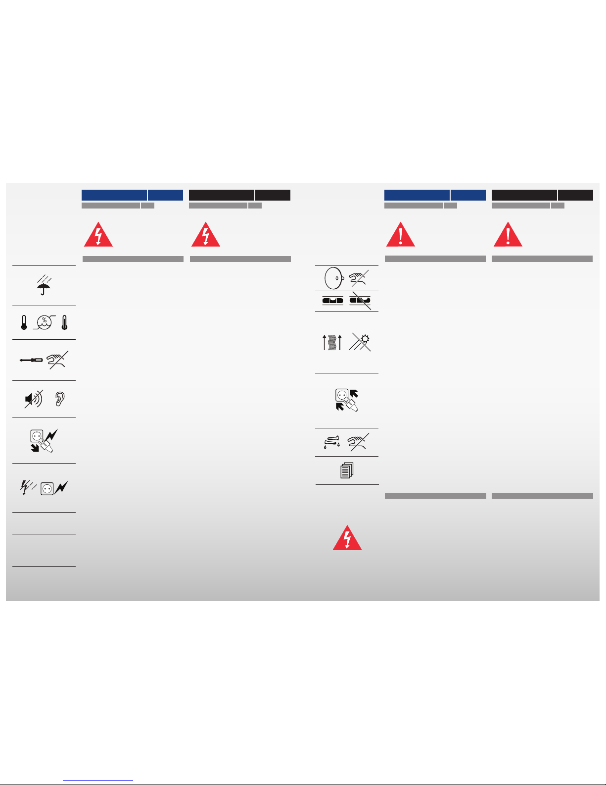
• Betriebsbedingungen:
Raumtemperatur 5 - 35 0C
Luftfeuchtigkeit 10 - 75%
• Um einen elektrischen Schlag zu vermeiden, die Gehäuse niemals öffnen. Wartungsarbeiten stets und ausschließlich vom autorisierten Fachpersonal ausführen lassen.
• Hohe Abhörlautstärken beeinträchtigen
das Hörvermögen und können zu bleibenden Gesundheitsschäden führen. Das Lautsprechersystem nicht zu laut stellen!
• Sollte ein fester Gegenstand oder Flüssigkeit in das Innere der Komponenten
gelangen, alle Geräte ausschalten und die
Komponenten vom autorisierten Fachpersonal überprüfen lassen, bevor Sie sie weiter
benutzen.
• Bei längerer Nichtbenutzung des HiFi–
Systems oder bei Gewittergefahr alle Geräte
von Stromnetz und Antennen trennen. Zum
Abtrennen die Netzkabel stets am Stecker
und niemals am Kabel selbst anfassen. Den
Stecker nie mit nassen Händen berühren.
• Die Geräte nur vom autorisierten Fachpersonal reparieren und installieren lassen.
• Diese Lautsprecher sind für die Wiedergabe von Tonsignalen bestimmt.Jede andere
Verwendung, insbesondere der gewerbliche
Betrieb, ist ausdrücklich ausgeschlossen.
VORSICHT
5 0C
35
0
C
10%
75%
• Beim Tragen immer nur an Gehäuse und
Fussrahmen halten.
• Die Lautsprecher auf eine ebene, solide
Fläche stellen.
• Gute Luftzirkulation ist wichtig, um einen internen Hitzestau zu vermeiden.
Die Lautsprecher an einem gut belüfteten Ort betreiben. Das System nicht in
die Nähe von Wärmequellen (z.B. Öfen,
Warmluftauslässe) stellen und nicht direkter
Sonnenbestrahlung, Staub oder mechanischer Vibration aussetzen.
• Alle elektrischen Verbindungen fest und
sicher anschließen. Die Stecker fest in die
Buchsen einstecken. Lockere Anschlüsse
können Brummen/Rauschen verursachen
und die Geräte beschädigen. Um sichere
Verbindungen zu gewährleisten, nur hochwertige Stecker verwenden.
• Um eine Beschädigung der Oberflächen zu
vermeiden, niemals Alkohol, Farbverdünner
oder Chemikalien verwenden.
• Diese Installations- und Bedienungsanleitung sorgfältig lesen, bevor das Lautsprechersystem in Betrieb genommen wird.
Vergewissern Sie sich vor der Inbetriebnahme der Komponenten, dass die Geräte
der örtlichen Netzspannung entsprechen:
Europa 230 V AC, 50 Hz
England 240 V AC, 50 Hz
USA, Kanada 120 V AC, 60 Hz
Andere Länder 120, 220 oder
240 V AC, 50/60 Hz
Sicherungen 3,15 A T bei 230 / 240 V
5,0 A T bei 120 V
INSTALLATIONSHINWEISE
NETZSPANNUNGEN / SICHERUNGEN
PRIVATE USE ONLY
• It is intended to alert the user of the presence of uninsulated “dangerous voltage“
within the products enclosure that may be
of sufficient magnitude to constitute a risk of
electrical shock to persons.
• Conditions for operation:
room temperature 5 - 35 0C
humidity 10 - 75%
• To prevent fire, shock or damage, do not
expose the components to rain or moisture.
To avoid electrical shock, do not open the
cabinet of the components. Refer servicing
to qualified personnel only.
• Excessive sound pressure levels might
cause serious damage to your health. Do
not operate the speaker system at excessive
levels for a long period of time.
• Should any solid object or liquid fall into
the cabinet of the components, unplug the
unit and have it checked by qualified personnel before operating it any further.
• Unplug the components of your system
from the wall outlet and antenna if they are
not to be used for an extended period of
time. To disconnect the power cord, pull it
out by the plug. Do not pull the cord itself.
Never touch the plugs with wet hands.
• Only let qualified personnel repair or reassemble the components of the system.
• These loudspeakers are designed for the
playback of audio signals. Any other use,
especially in commercial applications, is expressly prohibited.
CAUTION
! SERVICE !
SICHERHEIT SAFETY
• When lifting the speaker only hold to the
speaker enclosure and the speaker stand.
• Place the components of the system on a
flat solid surface.
• Good air circulation is essential to prevent
internal heat accumulation in the components. Place units in a location with sufficient
air circulation. Do not install the speakers in
a location near heat sources such as radiators, or in a place subject to direct sunlight,
excessive dust, or mechanical vibration.
• Connect everything securely. Always insert the plugs fully into the jacks. A loose
connection may cause hum pickup and can
damage the system. To prevent malfunction and short circuits, use only high quality
cables and plugs.
• To avoid damaging the finish, never use
alcohol, paint thinner or chemicals to clean
the components.
• Read this user manual thoroughly before
operating the speaker system.
Before connecting the speaker system to
the power source, check that the operating
voltage of the unit is the same as the local
power line voltage.
Europe 230 V AC, 50 Hz
United Kingdom 240 V AC, 50 Hz
USA, Canada 120 V AC, 60 Hz
Other countries 120, 220 or
240 V AC, 50/60 Hz
Fuses 3.15 A slow at 230 / 240 V
5.0 A slow at 120 V
PRECAUTIONS ON INSTAL
LATION
OPERATING VOLTAGE / MAINS FUSES
54
Page 4
SYSTEM INSTALLATION SYSTEM INSTALLATION
AUSPACKEN DES LAUTSPRECHERSYSTEMS UNPACKING THE SPEAKER SYSTEM
Beim Auspacken und Aufstellen das hohe
Gewicht der Lautsprecher beachten! Zur
Erleichterung empfehlen wir die Zuhilfenahme einer zweiten Person!
LIEFERUMFANG CONTENTS OF PACKAGING
• Verpackung des Lautsprechers:
2 x Papp-Kartonage mit den Lautsprechern
• 2 x Styrodur–Zubehörboxen:
1 x standard Fernbedienung mit 10 Tasten
runde Aluminium Fernbedienung
als Zubehör erhältlich
2 x Fussrahmen verchromt
2 x Netzkabel
• 1 x Kleinteilebox:
8 x Schrauben M8
8 x Unterlegscheiben M8
8 x Distanzscheiben Kunststoff
1 x Inbus-Schlüssel
• The packing of the system consists of:
2 x boxes with the 2 x speakers
• 2 x styrofoam accessory boxes contain:
1 x standard Remote control with 10 buttons
round aluminium Remote control
available as an accessory
2 x Speaker stand chrome
2 x Power cord
• 1 x cardboard box contain:
8 x Screws M8
8 x Washer M8
8 x Plastic spacers
1 x Allen key
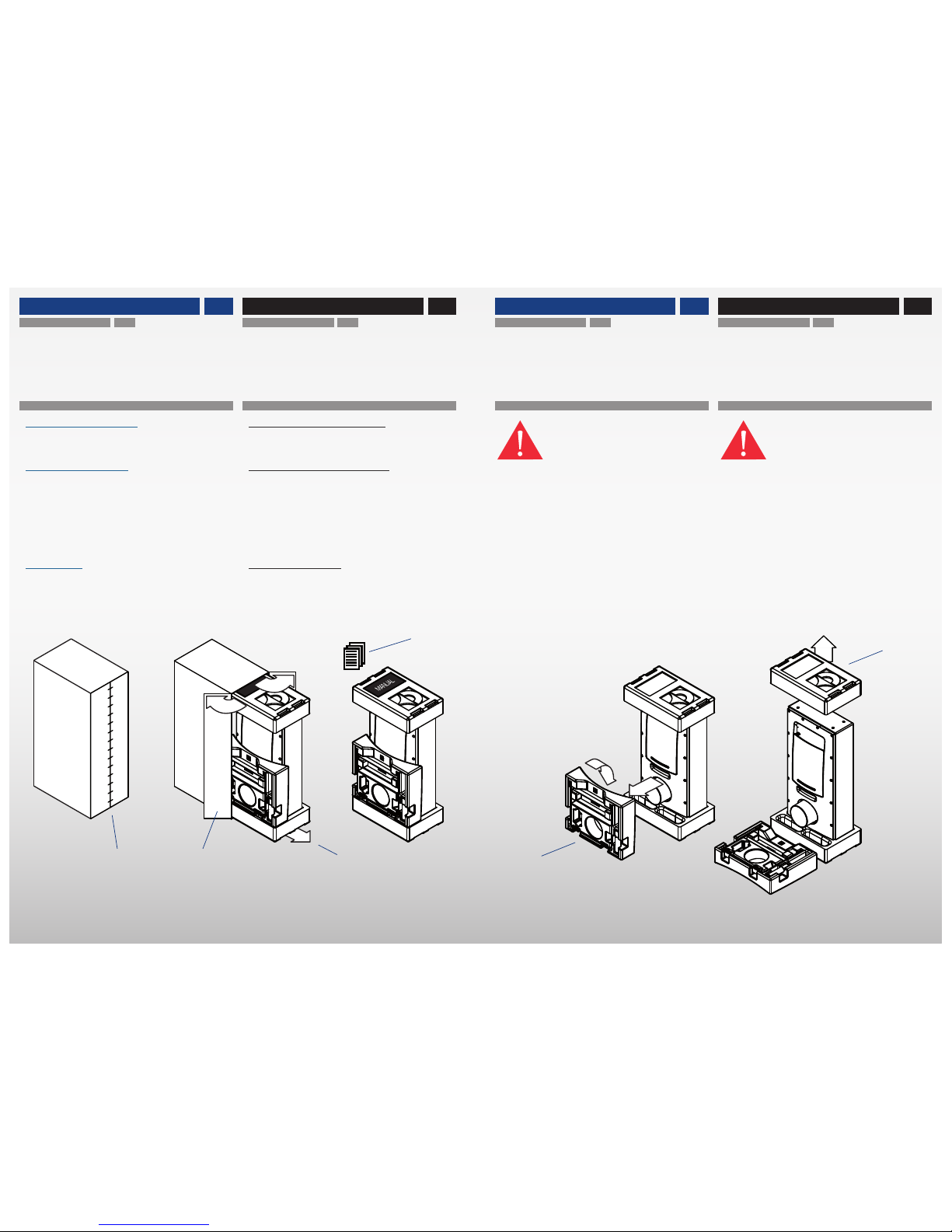
① Klammern entfernen
② Kartonage öffnen
③ Lautsprecher vorsichtig nach vorne herausziehen.
④ Bedienungsanleitung entnehmen und lesen.
⑤ Seitliche Styrodur–Zubehörverpackung abheben.
⑥ Obere Styrodur–Verpackung abheben.
① Remove the clamps.
② Open the box.
③ Carefully pull out the speaker to the front.
④ Read user manual.
⑤ Remove lateral styrofoam accessory box.
⑥ Remove upper styrofoam box.
Please note the heavy weight of the speaker
system when unpacking and installing the
system. We advise doing this work with the
help of a second person!
SYSTEM INSTALLATION SYSTEM INSTALLATION
④
① ② ③
⑤
76
⑥
Page 5
MONTAGE DES FUSSRAHMENS ATTACHING THE SPEAKER STAND
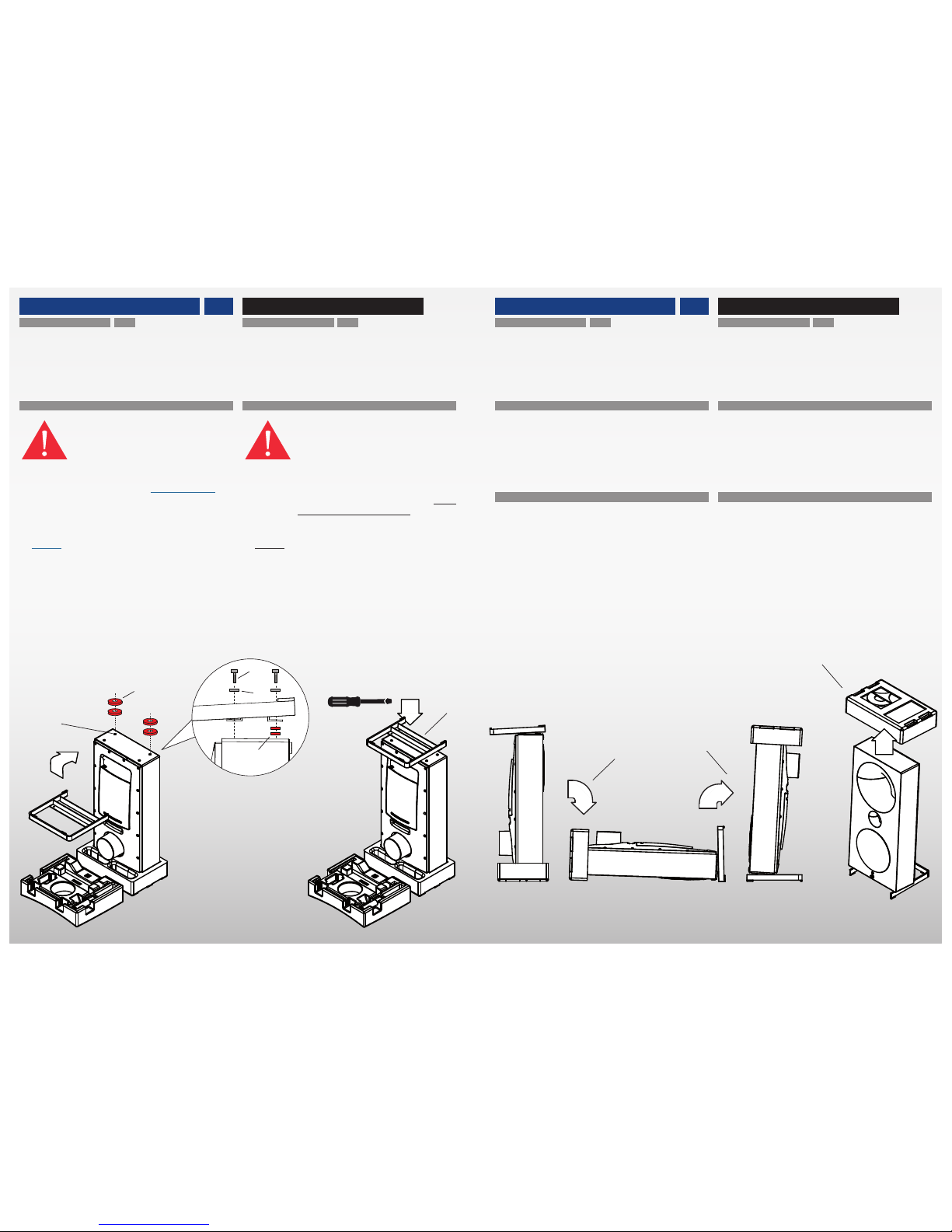
⑦ Optional: in order to increase the inclination of the sys-
tem, position 1—2 plastic spacers ❶ each on top of the
two threads facing to the front of the speaker.
⑧ Screw the speaker stand with the supplied M8 screws
❷ and washers ❸ onto the 4 x threads at the bottom-
side of the system by slowly turning them clockwise
until it obtains a tight fit. A good handtight force will
suffice, there is no need to use excessive force!
⑦ Optional: zum stärkeren Anwinkeln des Lautsprecher-
systems, je 1—2 x Kunststoff Distanzscheiben ❶ auf die
vorderen beiden Gewindebohrungen legen.
⑧ Mit den mitgelieferten M8 Schrauben ❷ den Fussrah-
men vorsichtig in die 4 x Innengewinde auf der Unterseite des Systems einschrauben. M8 Unterlegscheiben
❸ verwenden und Schrauben ❷ im Uhrzeigersinn einschrauben. Auf richtig festen Sitz achten. Dabei jedoch
keine übermäßige „Gewalt“ ausüben.
SYSTEM INSTALLATION SYSTEM INSTALLATION
AUFRICHTEN DES SYSTEMS TILTING THE SYSTEM
⑨ After the installation of the speaker stand, carefully lay
the speaker on its front.
⑩ Carefully lift up the system onto its speaker stand.
⑬ Remove upper styrofoam box.
SYSTEM INSTALLATION SYSTEM INSTALLATION
⑨ Das System mit montiertem Fussgestell vorsichtig nach
vorne auf die Vorderseite umlegen.
⑩ Das System vorsichtig aufrichten.
⑪ Obere Styrodur–Verpackung abheben.
Je nach Hörabstand und Höhe der Sitzposition ist die Neigung der Hornsysteme wichtig. Der Winkel kann durch Distanzscheiben
bei der Montage des Fussrahmens angepasst werden.
Lesen Sie deshalb vor der Montage des
Fussrahmens den Abschnitt „Neigung des
Systems“ auf der folgenden Seite.
Depending on the listening distance and the
height of your seat it might be important to
adjust the inclination of the system. The angle can be adjusted by using plastic spacers
when attaching the speaker stand.
Thus read the chapter “Inclination of the
System” on the following page, before
screwing-on the speaker stand.
LINKER UND RECHTER KANAL LEFT AND RIGHT CHANNEL
• Bitte beachten Sie, dass die Kanalzuordnung (linker bzw.
rechter Kanal) ab Werk vorprogrammiert ist und nur mit der
speziellen Zero 1 Software und einem Windows PC geändert werden kann. Die Zero 1 Software kann von der Avantgarde Acoustic Webseite heruntergeladen werden.
• Bei der Positionierung des Lautsprechers darauf achten,
dass:
MASTER = LINKER Kanal
SLAVE = RECHTER Kanal
• The channel assignment of the speakers (left or right
channel) is preprogrammed in the factory and can only
be changed with the special Zero 1 software running on
a Windows PC. The software can be downloaded from the
Avantgarde Acoustic website.
• When positioning the speakers, please make sure that:
MASTER = LEFT channel
SLAVE = RIGHT channel
⑦
⑧
⑨
⑩
98
⑨
❶
❶
❷
❸
⑪
Page 6
SYSTEM INSTALLATION SYSTEM INSTALLATION SYSTEM INSTALLATION SYSTEM INSTALLATION
NEIGUNG DES SYSTEMS INCLINATION OF THE SYSTEM
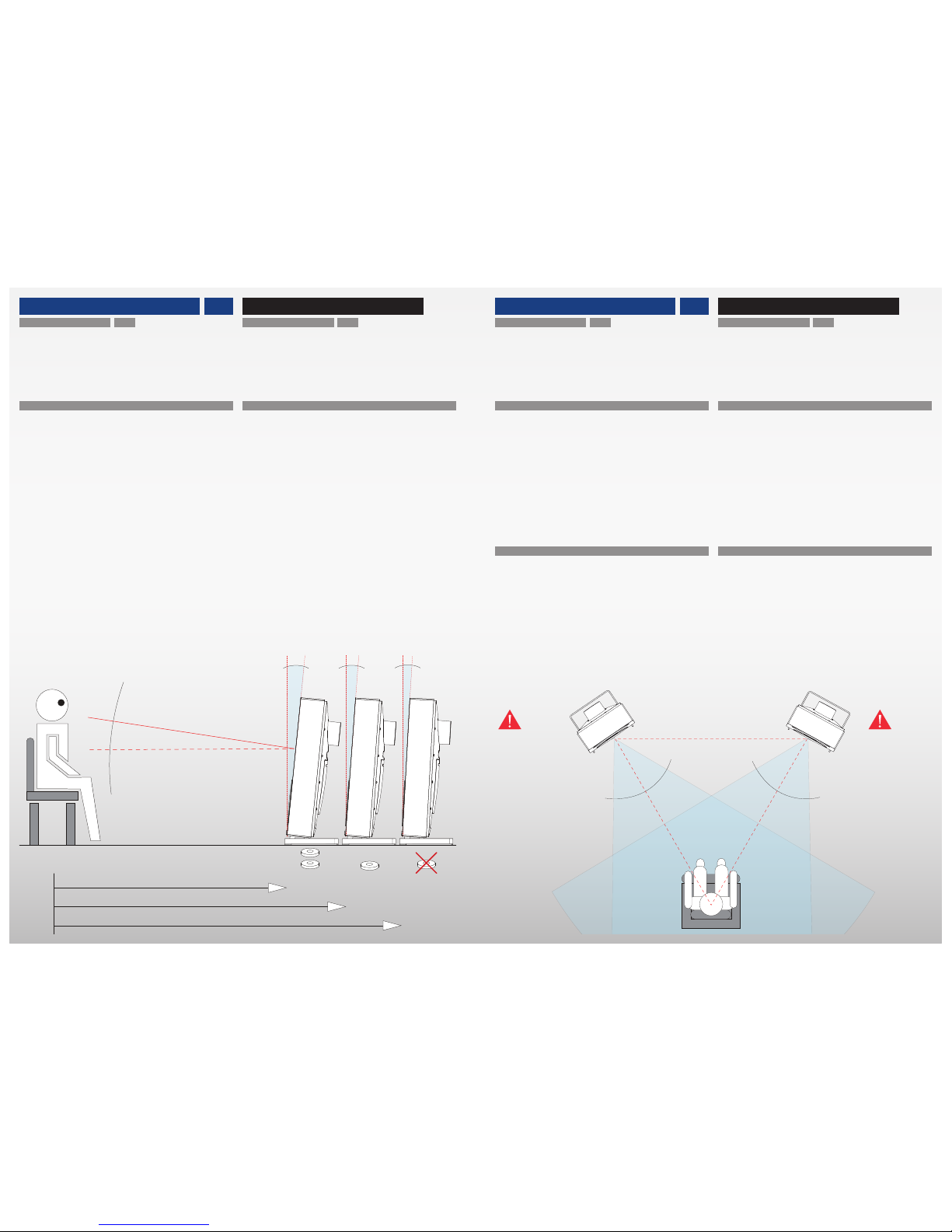
• Je nach Hörabstand und Höhe der Sitzposition ist die Neigung der Hornsysteme wichtig. Der Neigungswinkel des
Systems kann durch Distanzscheiben bei der Montage des
Fussrahmens von 3 auf 4 bzw. 5 Grad vergrößert werden.
• Der ideale Neigungswinkel kann durch ein Peilungs-Prinzip eingestellt werden.
Setzen Sie sich auf Ihren Hörplatz und schauen Sie auf den
Lautsprecher. Das Hochtonhorn sollte in etwa gerade auf
Sie (Augenhöhe) gerichtet sein.
D.h. je näher Sie vor dem Lautsprecher sitzen und je höher
Ihre Sitzposition ist, desto stärker sollte der Lautsprecher
angewinkelt sein.
Die folgende Grafik verdeutlicht diese Zusammenhänge und
dient als ausreichend präziser Anhaltspunkt bei der Erstinstallation.
• Depending on the listening distance and the height of your
seat it might be important to incline the speakers. The inclination can be increased from a 3 to a 4 or 5 degree angle
by using plastic spacers when attaching the speaker stand.
• The ideal inclination can be checked and aligned by a
simple “bearing” principle.
Have a seat and look at the speakers. The tweeter horn in
the middle of the system should be facing straight towards
you (ear height).
The more close you sit to the speaker and the higher your
sitting position is, the more the speaker should be inclined.
The below graphic show these dependencies and serve as
a mostly perfect rule of thumb during the initial installation.
kurzer Abstand / short distance ca. 2,0 — 2,8 m
mittlerer Abstand / mid distance ca. 2,8 — 3,8 m
großer Abstand / long distance ca. > 3,8 m
5 Grad
5 degree
4 Grad
4 degree
3 Grad
3 degree
PLAZIERUNG UND ANWINKELN DES SYSTEMS ROOM PLACEMENT AND TOE–IN OF SPEAKER
• Der Lautsprecher verursacht aufgrund der kontrollierten
Abstrahlcharakteristik der Hörner weniger unerwünschte
Reflexionen durch die Raumwände und kann deshalb auch
direkt vor der Rückwand bzw. in Raumecken (beide oder
nur ein Lautsprecher in der Ecke!) aufgestellt werden.
• Für die Systeme einen Standplatz wählen, an dem die
Lautsprecher und der bevorzugte Hörplatz annähernd ein
gleichseitiges Dreieck bilden. Idealerweise beträgt die Kantenlänge jeweils ca. 3,0m. Die Systeme sollten so angewinkelt werden, dass die Hörner direkt auf den Hörplatz zeigen.
• Due to the controlled dispersion characteristics of the
horns the speaker will excite less unwanted reflections
from the room walls and thus can be positioned directly in
front of back walls or close into corners (both or only one
speaker in the corner!).
• Choose a position for the speakers in your listening room.
Both speakers and your listening seat should form an approx. equilateral triangle. Ideally each side of the triangle
should be approx. 10 feet (3,0m). The speakers should be
toed-in with the horns pointing to the listening position.
FINE–TUNING BY TOE–IN OF SPEAKER
• Facing the speakers inwards or outwards (toeing–in, toeing–out) further affects the focus and tonal balance.
• By toeing–out, the sound is less “direct” or “forward
sounding”, but may affect the focus of the centre image.
• Toeing–in emphasizes increased focus on the centre image, but may affect the width of the stereo image.
FINE–TUNING DURCH ANWINKELN DES SYSTEMS
• Durch Ein– oder Auswinkeln der Lautsprecher können
Klangbalance und Fokus beeinflusst werden.
• Auswinkeln lässt das Klangbild weniger „direkt“ erscheinen. Durch zu starkes Auswinkeln kann jedoch die Mittenortung beeinträchtigt werden.
• Einwinkeln betont die Mittenortung. Durch zu starkes
Einwinkeln kann jedoch die Stereoabbildung beeinträchtigt
werden.
MASTER =
LINKER Kanal
LEFT channel
SLAVE =
RECHTER Kanal
RIGHT channel
3,0 m
3,0 m
3,0 m
60
0
60
0
1110
Page 7
GAIN
WIRE LINK
ANALOG INPUT
BALANCED
(OPTIONAL)
POWER
DIGITAL INPUTS
OPTUSB
SPDIF2
SPDIF1
AES/EBU LEFT RIGHT
BEDIENUNG OPERATION
DIGITALE EINGÄNGE
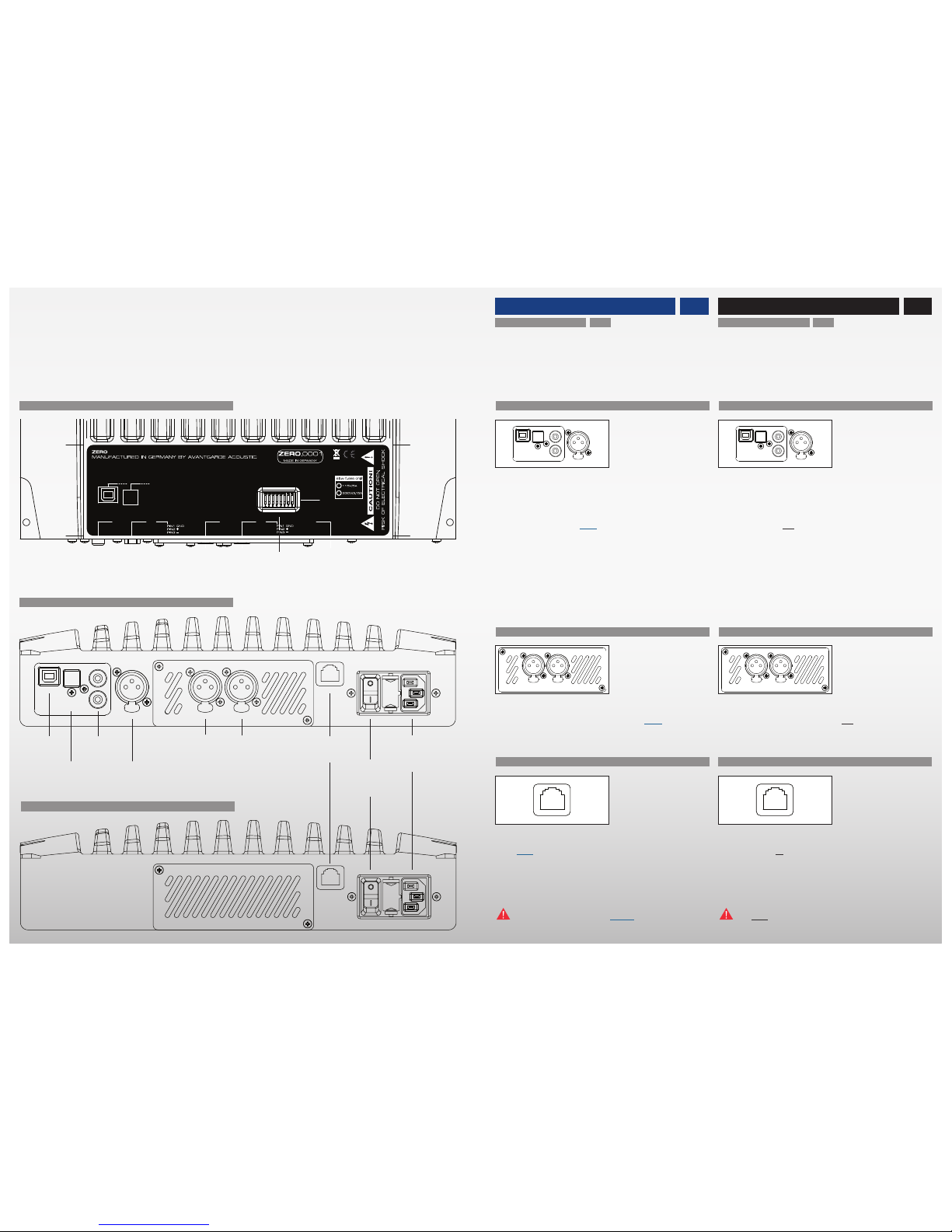
• Die digitalen Musikquellen mit den digitalen Eingängen
(USB ❶, TOSLINK ❷, SPDIF ❸ und/oder AES/EBU ❹)
des Master Lautsprechers (siehe Abb. links) verbinden.
• Der Lautsprecher ist nicht mit einem eingebauten WLAN
Empfänger ausgerüstet. Zur Integration des Lautsprechers
in einem Funknetz, eine externe WLAN Schnittstelle (z.B.
AirPort Express) über ein optisches TOSLINK Digitalkabel
mit dem TOSLINK ❷ Eingang des Lautsprechers verbinden.
Es können alle digitalen Eingänge gleichzeitig belegt
werden. Das Aktivieren des entsprechenden Eingangs erfolgt mit der Fernbedienung.
ANALOGER EINGANG (OPTIONAL)
• Optional ist ein analoger Eingang ❺-❻ erhältlich. Dieser
hochwertige Analog-Digital Konverter ist nicht im Standard
Lieferumfang enthalten, kann aber jederzeit vom authorisierten Service Personal nachgerüstet werden.
WIRE–LINK ZWISCHEN MASTER UND SLAVE
• Master und Slave Lautsprecher sind untereinander über
Funk oder optional einer Kabelverbindung (Wire–Link ❼)
verbunden. Hierfür Ethernet Kabel (CAT.5/5e/6 LAN Kabel
mit Standard 8P8C/RJ45 Stecker; 100 Ohm) verwenden.
Bei Verwendung des Wire–Links schaltet sich das Funk–
Modul automatisch aus.
Die Wire–Link ❼ Buchse NICHT zum Anschluss des
Lautsprechers an ein Ethernet Datennetz verwenden!
GAIN
WIRE LINK
ANALOG INPUT
BALANCED
(OPTIONAL)
POWER
DIGITAL INPUTS
OPTUSB
SPDIF2
SPDIF1
AES/EBU LEFT RIGHT
DIGITAL INPUTS
• Connect the digital music sources with the digital inputs
(USB ❶, TOSLINK ❷, SPDIF ❸ and/or AES/EBU ❹) of the
master speaker (see graphics left).
• The speaker is not equipped with an internal WLAN receiver. Connect an external WLAN interface (ex. AirPort
Express) through an optical TOSLINK cable with the
TOSLINK ❷ input of the master speaker, to integrate the
speaker in a WLAN environment.
All digital inputs can be connected at a time. The activation of the inputs is done with the remote control.
ANALOG INPUT (OPTIONAL)
• An analog input ❺-❻ is available an an option. This high
quality analog-digital converter is not included in the standard version of the system. The analog-digital converter can
be retrofitted anytime by authorized service staff.
WIRE–LINK BETWEEN MASTER AND SLAVE
• Master and slave speaker communicate with each other
via radio signal or alternatively via a Wire–Link ❼. For the
Wire–Link ❼ connection use an Ethernet Kabel (CAT.5/5e/6
LAN cable with standard 8P8C/RJ45 plug; 100 Ohm). The
radio module will automatically switch–off, when the Wire–
Link is connected.
Do NOT use the Wire–Link ❼ socket to connect the
speaker to an Ethernet computer network.
MASTER – AUFSICHT / TOP VIEW
SLAVE – SEITENANSICHT / SIDE VIEW
MASTER – SEITENANSICHT / SIDE VIEW
PIN 1 = GND
PIN 2 = hot
PIN 3 = cold
PIN 1 = GND
PIN 2 = hot
PIN 3 = cold
❶
❷
❸
❹
❺ ❻
❼
❽
❾
❿
1312
USB
TOSLINK OPT.
2 x SPDIF
AES/EBU
XLR ANALOG
(optional)
LEFT RIGHT
WIRE–LINK
ON/OFF
SWITCH
MAINS
INPUT
DIP–SWITCH
BASS RESPONSE
Page 8
BEDIENUNG OPERATION
EIN/AUS SCHALTER
Master und Slave Lautsprecher haben je einen 2–stufigen
Netzschalter ❽:
POSITION I : STANDBY oder EIN
POSITION O : AUS
POSITION I
• Das Gerät ist eingeschaltet und kann mit der Fernbedienung auf STANDBY und ON umgeschaltet werden. Im
Standby Betrieb ist das Gerät zwar am Netz angeschlossen
aber alle Audioschaltungen und die Audio Netzteile sind
ausgeschaltet (Standby Stromverbrauch < 0,5 Watt).
POSITION 0
• Die Stromversorgung des Lautsprechers ist ganz abgeschaltet. Zum Ausschalten kann der Netzschalter ❽ oder
ein externer Schalter (z.B. Steckerleiste) benutzt werden.
Bei längerer Abwesenheit sollten die Systeme ausgeschaltet und vom Netz getrennt werden. Unbedingt auch die
„Sicherheitshinweise“ in dieser Bedienungsanleitung lesen.
• Das beiliegende Netzkabel an der Kaltgerätebuchse ❾
anschließen. Alternativ können auch andere hochwertige
Netzkabel mit Kaltgerätestecker verwendet werden.
Der Betriebszustand wird durch die LED an der Vorderseite des Lautsprechers angezeigt:
LED AN: Gerät eingeschaltet
LED BLINKT: Gerät im Standby
LED AUS: Gerät ausgeschaltet
DIP–SCHALTER FÜR BASSPEGEL
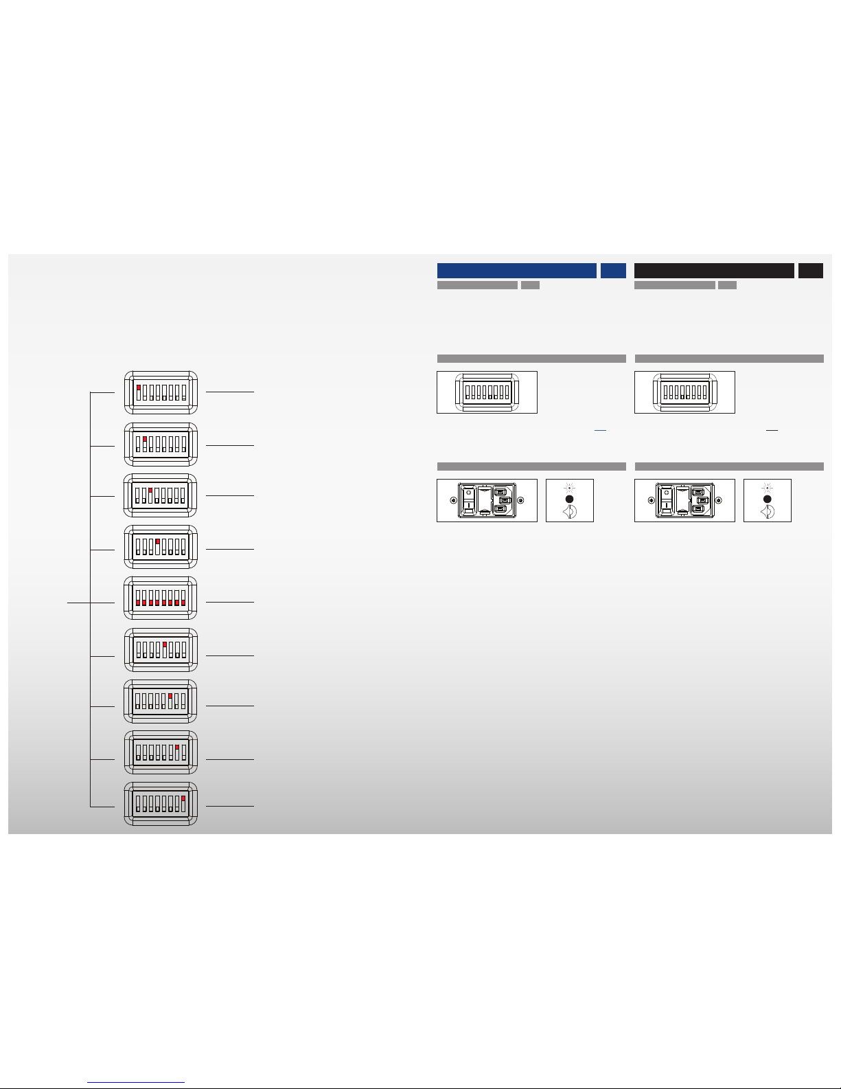
• Über einen 8–fachen DIP Schalter ❿ im Master und Slave
kann die Lautstärke der Basswiedergabe in 1 dB Schritten
von –4 dB bis + 4 dB angepasst werden (siehe Abb. links).
ON ON ONON ON ON ON ON
1 2 3 4 5 6 7 8
ON ON ON ON ON ON ON ON
1 2 3 4 5 6 7 8
ON ON ON ON ON ON ON ON
1 2 3 4 5 6 7 8
ON ON ON ON ON ON ON ON
1 2 3 4 5 6 7 8
ON ON ON ON ON ON ON ON
1 2 3 4 5 6 7 8
ON ON ON ON ON ON ON ON
1 2 3 4 5 6 7 8
ON ON ON ON ON ON ON ON
1 2 3 4 5 6 7 8
ON ON ON ON ON ON ON ON
1 2 3 4 5 6 7 8
ON ON ON ON ON ON ON ON
1 2 3 4 5 6 7 8
ON ON ON ON ON ON ON ON
1 2 3 4 5 6 7 8
ON/OFF SWITCH
Master and slave speaker each have a 2–position power
switch ❽:
POSITION I : STANDBY or ON
POSITION O : OFF
POSITION I
• The speaker is permanently „ON“ and can be toggled with
the remote control between STANDBY and ON. In Standby–
mode the unit is still connected to the mains, but all audio
circuits and audio transformers are completely turned off
(Standby power consumption is below 0,5 Watt).
POSITION 0
• The speaker is turned to permanent “OFF”. To turn the
system “Off” you can either use the Power–Switch ❽ or an
external power-switch. Turn the system “Off”, if your system is not in use over a longer period. Please carefully read
the “Precaution and Safety” instructions in this manual.
• The supplied power cord can be connected to the Mains
Input–Socket ❾. Alternatively you may use any other high
quality power cord that features the appropriate IEC plug.
The operation is indicated by the LED at the frontside of
the speaker:
LED ON: speaker switched on
LED FLASHING: speaker in standby
LED OFF: speaker switched off
DIP–SWITCH FOR BASS RESPONSE
• The 8–fold DIP switch ❿ in the master and slave speaker
allows to adjust the volume of the bass response in 1 dB
steps from –4 dB to + 4 dB (see graphics left).
ON ON ONON ON ON ON ON
1 2 3 4 5 6 7 8
1514
DIP 1 ON =
DIP 2 ON =
DIP 3 ON =
DIP 4 ON =
STANDARD =
DIP 5 ON =
DIP 6 ON =
DIP 7 ON =
DIP 8 ON =
+ 4 dB
+ 3 dB
+ 2 dB
+ 1 dB
0 dB
– 1 dB
– 2 dB
– 3 dB
– 4 dB
❿
Page 9
FERNBEDIENUNG REMOTE CONTROL
EINGANGSTASTER
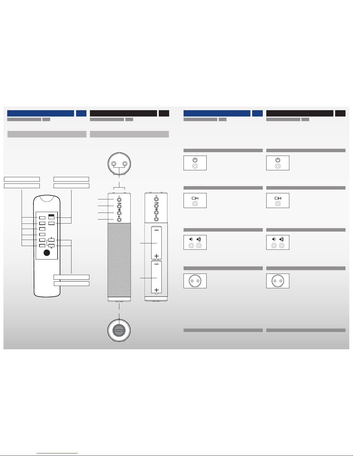
• Drücken der Eingangstaste ⓬ schaltet zwischen den Eingängen (USB ❶, TOSLINK ❷, SPDIF ❸, AES/EBU ❹ und
ANALOG ❺❻) um.
INFRAROT SENDER
• Die beiden Infrarot Sender ⓯ befinden sich an der Vorderseite der Fernbedienung. Für einen guten Empfang des
Infrarot Signals die Fernbedienung in Richtung Empfänger
Sensor des Master Lautsprechers halten. Der IR Sensor
befindet sich frontseitig oberhalb des verchromten Logos.
Starke Lichtquellen oder Sonnenlicht können den Infrarot Empfang beeinträchtigen.
AUSTAUSCH DER BATTERIEN
• Zum Einsetzen bzw. Austauschen der beiden 1,5V Typ AA
Batterien ⓱ und ⓲ den Schraubdeckel des Batteriefachs
⓰ mit Münze entgegen dem Uhrzeigersinn aufschrauben.
STANDBY TASTE
• Drücken der Standby Taste ⓫ schaltet zwischen
STANDBY– und ON–Betrieb um.
LAUTSTÄRKEREGLUNG
• Drücken der Lautstärketaste ⓭ erhöht die Lautstärke.
• Drücken der Lautstärketaste ⓮ senkt die Lautstärke.
REMOTE CONTROL – INPUT SWITCH
• Pressing the input switch ⓬ toggles between the inputs (USB ❶, TOSLINK ❷, SPDIF ❸, AES/EBU ❹ and
ANALOG ❺❻).
REMOTE CONTROL – INFRARED TRANSMITTER
• Both infrared emitters ⓯ are located at the frontside of
the remote control. Point the remote control towards the infrared sensor of the Master speaker to ensure good reception. The IR sensor is located at the front side of the Master
speaker above the Avantgarde chrome logo.
Strong sources of light or direct sunlight may interfere
and disable the infrared reception.
CHANGING THE BATTERIES
• To insert or replace the two 1.5V Typ AA batteries ⓱ and
⓲ open the round screw cap of the battery compartment ⓰
with a coin by turning it counter–clockwise.
REMOTE CONTROL – STANDBY SWITCH
• Pressing the standby switch ⓫ toggles between
STANDBY and ON.
REMOTE CONTROL – VOLUME CONTROL
• Pressing the volume button ⓭ increases the volume.
• Pressing the volume button ⓮ decreases the volume.
ZERO 1
by Avantgarde Acoustic
USB
OPT
COAX 1
COAX 2
AES
ANALOG
ON
VOL
OFF
FERNBEDIENUNG REMOTE CONTROL
STANDARD
• im Lieferumfang enthalten
• included as standard
OPTIONAL
• als Zubhör erhältlich
• available as an option
1718
16
⓯
⓫
⓬
⓭
⓲
⓰
⓮
⓱
EIN-/AUS Taster
ON/OFF Switch
LAUTSTÄRKE Taster
VOLUME Control
EINGANGS Taster
INPUT Select
Page 10
FINE–TUNING TIPPS FINE–TUNING TIPS
BURN–IN TIME
• The speaker system usually need at least 40 hrs. of running-in. During this period sound quality will improve “minute by minute”. After this time it may be necessary to check
and correct the system set-up, positioning and bass level
settings (DIP switch ❿) . Please leave the system switched
ON during this run-in period.
EINSPIELZEIT
• Für das Lautsprechersystem gilt gewöhnlich eine Einspielzeit von mindestens 40 Std. Danach kann es nötig sein,
die Aufstellung der Systeme sowie die Einstellungen des
Basspegels (DIP Schalter ❿) nochmals zu überprüfen und
gegebenenfalls zu korrigieren. Für die Dauer dieser ersten
Einspielzeit das Lautsprechersystem möglichst kontinuierlich am Netz lassen.
RADIO LINK & REINIGUNG RADIO LINK & CLEANING
CLEANING OF THE SOFT–TOUCH SURFACES
• We recommend to regularly clean the soft–touch surfaces
of the speaker system with a dry soft fabric (duster).
• To remove finger prints and dirty spots on the soft–touch
surfaces we recommend the use of glass detergent or care
products for the interior of automobiles.
• Heavy stains can be cleaned with liquid soap and a soft
brush. Depending on the kind of stains ethyl alcohol + soft
fabric or a magic sponge is maybe advisable.
Never use cleaning agents for lavatories and toilets!
To be on the safe side: first apply glass detergent on the
backside of the horns to test the result!
Do not touch the membranes while cleaning the speaker!
Avoid scratching the surfaces with dirty fabrics and
never use aggressive detergents or abrasives!
REINIGUNG DER–SOFT TOUCH OBERFLÄCHEN
• Wir empfehlen die lackierten Soft–Touch Oberflächen des
Lautsprechers regelmäßig mit einem trockenen, weichen
Staubtuch zu reinigen.
• Zur Entfernung von Flecken oder Fingerabdrücke
handelsüblichen Fensterreiniger oder Pflegestoffe aus dem
Automobil Innenbereich verwenden.
• Hartnäckiger Flecken oder Fingerabdrücke mit Flüssigseife und einer weichen Bürste reinigen. Weitere erprobte
Reinigungsmethoden sind Spiritus + ein weiches Tuch und
Magic Sponge bzw. Schmutzradierer.
Niemals Scheuermittel aus dem Badbereich verwenden!.
Reinigungsmittel erstmalig zum Testen nur auf der Rück-
seite des Lautsprechers verwenden!
Beim Reinigen nicht die Membranen berühren!
Kratzer durch schmutzige Tücher oder aggressive bzw.
abrasive Reinigungsmittel vermeiden.
CLEANING OF THE METAL SURFACES
• Clean the powder coated surface of the amplifier heat sink
with a regular duster or slightly moisted (i.e. by glass detergent) piece of cloth.
REINIGUNG DER METALL OBERFLÄCHEN
• Die pulver–beschichtete Oberfläche des Kühlkörpers mit
einem trockenen oder feuchten (z.B. Glasreiniger) Staubtuch reinigen.
AUDIO EINSTELLUNGEN DES MUSIK PLAYERS
• Die Zero 1 ist ein sehr hochwertiges Lautsprechersystem, das in der Lage ist, ein überragendes Klangerlebnis
zu erzeugen. Die Klangqualität wird jedoch nicht nur vom
Lautsprecher, sondern auch durch die Qualität der wiedergegebenen Musikformate und den Einstellungen der Audio
Abspielgeräte determiniert.
• Um einen optimalen Hörgenuss zu gewährleisten, empfehlen wir deshalb, unbedingt die folgenden Punkte zu beachten:
Verwenden Sie keine datenreduzierten Musikformate
(MP3 etc.), sondern ausschließlich hochwertige unkomprimierte Musikformate (WAV, FLAC, LOSSLESS* etc.)
Bei Smartphones, Tablets (z.B.. iPad*) oder Computer
als Abspielgerät stellen Sie unbedingt sicher, dass alle sogenannten „Klangverbesserungen“ ausgeschaltet sind. Dies
betrifft insbesondere die folgenden Audio Einstellungen von
Smartphones, Tablets und Computern:
• Lautstärkeeinstellung im Player (iTunes*) MAX
• Automatische Lautstärkeanpassung AUS
• Equalizer AUS
• Maximale Lautstärke AUS
AUDIO SETTINGS OF PLAYBACK DEVICE
• The Zero 1 is a very sophisticated speaker system. It is capable of generating an unforgettable sound experience. But
please keep in mind, that the achieved sound quality does
not only depend on the speaker system, but is determined
as well by the quality of the music formats and the settings
of the audio playback devices.
• To ensure a perfect sound, we thus recommend to strictly
follow the below recommendations:
Do not use compressed music formats (MP3 etc.) but
only use high quality uncompressed music formats (WAV,
FLAC, LOSSLESS* etc.)
If you use a smartphone, tablet (ex. iPad*) or computer
as a playback device make sure the so-called “sound enhancements” are switched off. Especially this applies to
the following audio settings of smartphones, tablets and
computers:
• Volume setting of the player (iTunes*) MAX
• Automatic sound check / SPL adjust OFF
• Equalizer OFF
• Volume limit OFF
DIGITAL VOLUME CONTROL
• Smartphones, tablets (ex. iPad*) or computer allow to
adjust the listening volume directly within the player (ex.
iTunes*). This digital volume control decreases the quality
of the music signal by 1 Bit per –6 dB. I.e. at a „normal“
listening level (approx. –48 dB) the resolution of the music
signal is decreased by 8 Bit!
Set the volume of your player (ex. iTunes*) always to
MAX. Only use the volume buttons ⓭ ⓮ of the supplied
remote control to set the volume.
DIGITALE LAUTSTÄRKEREGELUNG
• Smartphones, Tablets (z.B.. iPad*) oder Computer ermöglichen es, die Lautstärke direkt im Player (z.B. iTunes*)
einzustellen. Bei dieser digitalen Lautstärkeregelung kommt
es jedoch zu einem Auflösungsverlust von 1 Bit pro –6 dB.
D.h. bei „normaler“ Abhörlautstärke (ca. –48 dB) reduziert
sich die Auflösung des Musiksignals um 8 Bit!
Stellen Sie die Lautstärke im Player (z.B. iTunes*) auf
MAX. Immer die mitgelieferte Fernbedienung des Lautsprechers ⓭ ⓮ zur Einstellung der Lautstärke verwenden.
* eingetragene Marke der Apple Inc., Cupertino California, USA
* registered trademark of Apple Inc., Cupertino California, USA
WIRELESS LINK BETWEEN MASTER & SLAVE
• The radio link between master & slave speaker uses
the 2.4 GHz band. This public frequency band is used by
multitude of products and services (Wifi, Bluetooth, TVs
etc.). This congestion of available radio space can cause
interferences. Dropouts in sound might occure.
In these cases use the Wire-Link between Master &
Slave speaker. See page 13.
FUNKVERBINDUNG ZWISCHEN MASTER & SLAVE
• Die Funkstrecke zwischen Master & SLave Lautsprecher
arbeitet im 2.4 GHz Band. Dieser öffentliche Bereich wird
von einer Vielzahl von Geräten (Wifi, Bluetooth usw.) verwendet. Es kann zu gegenseitigen Störungen (z.Bsp. kurzzeitige Aussetzer im Ton) kommen.
In diesem Fall den Wire-Link zwischen Master & Slave
verwenden. Siehe S. 13
1918
Page 11

GARANTIE WARRANTY
WARRANTY TERMS
• Avantgarde Acoustic™ Lautsprechersysteme GmbH warrants that the products are free from defects attributable to
faulty manufacture. The warranty is limited to ten (10) years
for material fatigue of the metal parts and plastic parts,
five (5) years for the color coating and drivers, and two (2)
years for all electronic components.
• All products Avantgarde Acoustic™ have been thoroughly
checked before shipping. In the case of problems, please
check the following:
1. This warranty begins on the date of original purchase and
may be enforced only by the original purchaser. Please keep
the original dated sales slip as proof of warranty coverage.
The warranty period is not effected by warranty services
provided within the warranty period.
2. Except as specified below, this warranty covers all defects in material and workmanship in this product. Our liability for any defective product is limited to repair or replacement of the products, at our option. Any implied warranties,
including warranties of merchantabilities and fitness for a
particular purpose, or damages based upon inconvenience,
loss of use of the product, or commercial loss, or any other
damages are not covered by this warranty.
3. Any modification, alterations or changes to the product
are strictly prohibited.
4. In case of defects, pleases contact at first your dealer. If
at the sole descretion of Avantgarde Acoustic™ it is necessary to ship the product to the manufacturer, please make
sure that:
• The product is carefully packed and shipped in its original
shipping box.
• The product is shipped free of charge to us, e.g. you must
pay all shipping charges (ex. freight, insurance etc.).
GARANTIE BESTIMMUNGEN
• Avantgarde Acoustic™ Lautsprechersysteme GmbH gewährleistet, dass die Geräte keine fertigungsbedingten
Fehler haben. Die Garantie beträgt zehn (10) Jahre auf Materialermüdung der Metallteile und der Kunststoffteile, fünf
(5) Jahre auf den Lack und die Treiber, sowie zwei (2) Jahr
auf die Elektronik.
• Die Geräte von Avantgarde Acoustic™ wurden vor der
Auslieferung messtechnisch kontrolliert und geprüft. Sollten Sie dennoch einmal Probleme mit Ihren Geräten haben,
beachten Sie bitte Folgendes:
1. Die Garantiezeit beginnt mit dem Kauf des Gerätes und
gilt nur für den Erstbesitzer. Als Nachweis über das ursprüngliche Kaufdatum bewahren Sie bitte die OriginalRechnung auf. Die Garantiezeit wird von einer Garantieleistung durch uns nicht berührt.
2. Während der Garantiezeit beseitigen wir unentgeltlich
etwaige Mängel, die nachweislich auf Material- oder Fabrikationsfehlern beruhen, nach unserer Wahl durch Reparatur oder Austausch der Geräte. Weitergehende Ansprüche,
insbesondere solche auf Minderung, Wandlung, Schadensersatz oder durch Folgeschäden sind ausgeschlossen.
3. Am Gerät dürfen keine unsachgemäßen Eingriffe vorgenommen worden sein.
4. Bei Inanspruchnahme der Garantie wenden Sie sich bitte
zunächst an Ihren Fachhändler. Sollte es sich nach Ermessen von Avantgarde Acoustic™ als notwendig erweisen das
Gerät an uns einzuschicken, so sorgen Sie bitte dafür, dass:
• Das Gerät in einwandfreier Originalverpackung verschickt
wird.
• Das Gerät frachtfrei zugestellt wird, d.h. Frachtkosten,
Porto und Risiko zu Ihren Lasten.
GARANTIE WARRANTY
WARRANTY TERMS (cont.)
5. The following are not covered by this warranty:
• Regular inspections, tuning, repairs or replacement of
parts which are attributable to normal wear and tear.
• Damage occuring during shipment of the product. All
transport claims must be presented to the carrier.
• Damages or scratches on the surface of the product (ex.
housing, horns, metal parts, color coating etc.). These
claims must be presented within 3 days after the date of
original purchase with your dealer.
• Damage resulting from incorrect placement, faulty connections, improper operation. Damage resulting from failure
to follow instructions supplied with the product.
• Damage resulting from accident, misuse, abuse, neglect,
electrical surges, lightning or other acts of God.
• Damage resulting from repair or attempted repair by
anyone other than Avantgarde Acoustic™ or an authorized
Avantgarde Acoustic™ dealer.
• Consequential, secondary or subsequent damages to
other third party appliances.
6. Some states do not allow limitations on how long an implied warranty lasts and/or do not allow the exclusion or
limitation of incidental or consequential damages, so the
above limitations may not apply to you.
7. The warranty card supplied with the product has to be
filled in correctly and in case of a warranty claim be send to:
Avantgarde Acoustic™ Lautsprechersysteme GmbH
Nibelungenstr. 349
D-64686 Lautertal - Reichenbach
Germany
GARANTIE BESTIMMUNGEN (Fortsetzung)
5. Von der Garantie ausgeschlossen sind:
• Regelmäßige Inspektionen, Wartung bzw. Reparatur oder
Austausch von Teilen bedingt durch normalen Verschleiß.
• Transportschäden, sichtbar oder unsichtbar. Reklamationen sind umgehend bei der Transportfirma einzureichen.
• Kratzer in Lackoberflächen, Hörnern, Gehäuseteilen usw.
Diese Defekte müssen innerhalb von 3 Tagen nach dem
Kauf direkt bei Ihrem Händler reklamiert werden.
• Fehler, die durch fehlerhafte Aufstellung, falschen Anschluss, unsachgemäße Bedienung oder Beanspruchung
und äußere gewaltsame Einwirkung entstanden sind.
• Unfälle, höhere Gewalt oder andere nicht von Avantgarde
Acoustic™ zu verantwortende Ursachen.
• Unsachgemäß reparierte oder geänderte Geräte, die von
anderer Seite als von Avantgarde Acoustic™ oder unseren
autorisierten Fachhändlern geöffnet wurden.
• Folgeschäden an fremden Geräten.
6. Diese Garantie schränkt weder die gesetzlichen Rechte
des Verbrauchers nach dem jeweils geltenden nationalen
Recht noch die Rechte des Verbrauchers gegen den Verkäufer aus dem zwischen ihnen abgeschlossenen Kaufvertrag ein.
7. Die beiliegende Garantiekarte muss beim Gerätekauf
vollständig ausgefüllt und im Garantiefall vorgelegt werden
beim Hersteller:
Avantgarde Acoustic™ Lautsprechersysteme GmbH
Nibelungenstr. 349
D-64686 Lautertal - Reichenbach
Germany
2120
Page 12

NOTIZEN
NOTES
NOTIZEN
NOTES
2322
Page 13

purity
performance
Avantgarde Acoustic GmbH
Nibelungenstraße 349
D-64686 Lautertal
Germany
www.avantgarde-acoustic.de
ZERO 1 User Manual
Version 2.0, January 3, 2015
 Loading...