

Avantco 177AG24MG, 177AG36MG, 177AG24RC, 177AG48RC, 177AG36RC Installation Operation & Maintenance
...
02/2019
INSTALLATION, OPERATION & MAINTENANCE
AVANTCO SERIES 177AG OWNER’S MANUAL
Manual Griddles:
Radiant Charbroilers:
Hot Plates:
All equipment manufactured by Avantco is for use with the type of gas specified on the rating plate
and for installation that will be in accordance with National Fuel Gas Code ANSI Z223.1 (latest edition).
FOR YOUR SAFETY: Do not store or use gasoline or other flammable vapors
or liquids in the vicinity of this or any other appliance.
WARNING: Improper installation, adjustment, alteration, service or
maintenance can cause property damage, injury or death. Read the installation,
operating and maintenance instructions thoroughly before installing or
servicing this equipment.
177AG24MG • 177AG36MG • 177AG48MG
177AG24RC • 177AG36RC • 177AG48RC
177AGR212 • 177AGR424 • 177AGR636
Instructions to be followed in the event the user smells gas must be posted in a prominent
location in the kitchen area. This information shall be obtained from the local gas supplier.
PLEASE RETAIN THIS MANUAL FOR FUTURE REFERENCE
This equipment is design engineered for commercial use only.
Page | 1

TABLE OF CONTENTS
Installation Instructions.......................................................................2
Operating Instructions .....................................................................3-4
Cleaning & Maintenance Instructions ..........................................................5
Conversion .................................................................................6
Specifications...............................................................................7
Equipment Diagrams ..................................................................... 8-16
Warranty .................................................................................. 17
INSTALLATION INSTRUCTIONS
• Installation of the equipment should be performed by qualified, certified and authorized
personnel who are familiar and experienced with local installation codes.
• Before installation, please read instructions completely and carefully.
• Do not remove permanently axed labels, warnings or plates from the product.
SHIPPING DAMAGE CLAIM PROCEDURE
1. Visible loss or damage: Note on freight bill or express delivery and have signed by
person making delivery.
2. File claim for damages immediately: Regardless of the extent of damages.
3. Concealed loss or damage: if damage is noticed after unpacking, notify transportation
company immediately and file “Concealed Damage” claim with the transportation carrier.
This should be done within five (5) days from the date of delivery and receipt of goods.
Retain container for inspection.
• Please observe all local and national codes and ordinances.
• Installation must conform with local codes, or in the absence of local codes, the National
Fuel Gas Code, ANSI Z223.1 (latest edition). In Canada, installation should conform to
installation codes for gas burning appliances and equipment standard CAN/CGA-B149.1
or the propane installation code, CAN/CGA-B149.2, as applicable.
• Electrical wiring to the appliance must be electrically grounded in accordance with local
codes or in the absence of local codes with the National Electrical Code ANSI/NFPA 70,
or the Canadian Electrical Code, CSA C22.2, as applicable.
• A manual gas shut-o valve must be installed in the gas supply line ahead of the
appliance and gas pressure regulator for safety and ease in servicing.
• The gas pressure regulator supplied must be installed on the appliance prior to
connecting the equipment to the gas line. Failure to install a regulator could be
potentially hazardous and will void the appliance warranty.
• The appliance and its individual shut o valve must be disconnected from the gas supply
piping system during any pressure testing of that system at test pressures in excess of ½
psi (3.45kpa).
• The appliance must be isolated from gas supply piping system, by closing its individual
manual shut o valve during any pressure testing of the gas supply piping system at test
pressures equal to or less than ½ psi (3.45kpa).
Page | 2
OPERATING INSTRUCTIONS
Operation of this equipment must be performed by qualified or authorized personnel who
have read and are familiar with the functions of the equipment.
MAINTENANCE
To perform maintenance and repairs of the appliance, please contact the factory, the factory
representative, or the nearest authorized local service company.
RATING PLATE
Information on this plate includes the model, serial number, BTU/hour input of the burners,
operating gas pressure in inches WC, and whether the appliance is orificed for natural or
propane gas. When communicating with factory about a unit or requesting special parts or
information, rating plate data is essential for proper identification.
AVANTCO COOKING APPLIANCES MUST BE CONNECTED ONLY
TO THE TYPE OF GAS IDENTIFIED ON THE RATING PLATE
CLEARANCES
The appliance area must be kept free and clear of all combustibles.
Combustible Non-Combustible
AVANTCO MODEL
Rear Sides Rear Sides
177AG (24/36/48) MG - Manual Griddles 8” 10” 0” 0”
177AG (24/36/48) RC - Radiant Charbroilers 8” 10” 0” 0”
177AGR (212/424/636) - Hot Plates 8” 10” 0” 0”
AIR SUPPLY AND VENTILATION
The area in front of, around, and above the appliance must be kept clear to avoid any
obstruction of the flow of combustion and ventilation of air.
Adequate clearance must be maintained around the appliance for easy servicing.
Provisions should be made for any commercial, heavy duty cooking appliance to have its
exhaust combination waste products released to the outside of the building. The usual
practice is to place the appliance under an exhaust hood, which should be constructed in
accordance with local codes.
Strong exhaust fans in this hood or in the overall air conditioning system can produce a slight
vacuum in the room and/or cause air drafts, either of which can interfere with the pilot or
burner performance and could be dicult to diagnose. Air movement should be checked
during installation. Air openings or baes may have to be provided in the room, if pilot or
burner outage problem persists.
GAS CONNECTION
The gas supply (service) line must be the same size or greater than the inlet line of the
appliance. Avantco appliances use a ¾” NPT inlet. Sealant on all pipe joints must be resistive
to LP gas.
MANUAL SHUT OFF VALVE
This installer-supplied valve must be in the gas service line ahead of the appliance regulator
in the gas stream and in position accessible in the event of an emergency.
Page | 3
PRESSURE REGULATOR
Commercial cooking equipment must have a pressure regulator on the incoming service line for
safe and ecient operation, since service pressures may fluctuate on local demand. A pressure
regulator is packed inside every Avantco appliance.
FAILURE TO INSTALL THE PRESSURE REGULATOR WILL VOID THE APPLIANCE WARRANTY
The regulators supplied along with Avantco appliances will have ¾” inlet/outlet openings.
Prior to connecting the regulator, check the incoming line pressure as these regulators can only
withstand a maximum pressure of ½ psi (14” WC). If the line pressure is beyond this limit, a step
down regulator will be required.
The arrow shown on the bottom of the regulator body shows the gas flow direction, it should
point downstream to the appliance. The red air vent cap on the top is part of the regulator and
should not be removed.
Any adjustments to the regulator should be made only by qualified service personnel with the
proper equipment.
CONNECTIONS
Please check installer-supplied intake pipes visually and/or blow them with compressed air to
clear any dirt particles, threading chips, or any other foreign matter before installing a service line.
When gas pressure is applied, these particles could clog orifices. All connections must be sealed
with a joint compound suitable for LP gas, and all connections must be tested with a soapy water
solution before lighting any pilots.
CAUTION: When lighting pilots and checking for leaks, do not stand with your
face close to the combustion chamber.
INITIAL PILOT LIGHTING
Check all gas connections for leaks with a soapy water solution before lighting any pilots.
LIGHTING & SHUTDOWN
• Turn all valves to the OFF position.
• Wait for 5 minutes.
• Turn pilot valve(s) by adjusting the screw counter clockwise, then light standing pilot and
adjust flame to ¼” high.
• Turn ON gas valve(s) to light the main burner.
• For complete shutdown, shut OFF gas valve(s) and turn pilot valve(s) by adjusting the screw
clockwise to shut o gas to the pilot(s)
BEFORE GRIDDLES 1ST USE
• Clean the griddle surface thoroughly with hot, soapy water to remove factory-applied
protective oil coating.
• Rinse with a mixture of ¼ cup vinegar to 1 qt. water.
• Spread unsalted solid shortening or liquid frying compound evenly over the entire griddle
surface.
• Turn all griddle burners to medium and wait until the shortening begins to smoke, then turn the
burners OFF.
• Rub the now melted shortening into the griddle surface with burlap, moving in the direction of
the surface’s polish marks and covering the entire surface.
• Allow the griddle to coool.
• When the griddle is cool after the second seasoning, wipe it with a thin film of shortening or
cooking oil.
Page | 4

CLEANING & MAINTENANCE INSTRUCTIONS
Any equipment works better and lasts longer when maintained properly. Cooking equipment
is no exception. Your Avantco appliance must be cleaned on a daily basis.
DAILY MAINTENANCE
OPEN BURNERS
1. Remove all top grates.
2. Lift o the burner heads and venturi by raising the head slightly, sliding to the rear of the
range, and lifting upwards.
3. Wash o the above in hot soapy water.
4. Reinstall burner parts in the reverse order.
GRIDDLES
1. Scrape with a nylon griddle scraper to remove the cooked spills. When absolutely
necessary, use a fine grained stone to scrape.
2. Wipe away any griddle stone dust and food particles with burlap.
3. Wash with hot, soapy water, then rinse with vinegar and water.
4. Rinse again with clear water.
5. Re-oil with shortening or liquid frying compound.
6. DO NOT FLOOD A HOT GRIDDLE WITH COLD WATER. This could cause warping and the
griddle plate to crack.
STAINLESS STEEL
All stainless steel body parts should be wiped regularly with hot soapy water during the day
and with a liquid cleaner designed for this material at the end of each day. DO NOT USE
steel wool, abrasive cloth, or powders to clean stainless surfaces. If it is necessary to scrape
stainless steel to remove encrusted materials, soak in hot water to loosen the material, then
use a wood or nylon scraper. DO NOT USE a metal knife, spatula, or any other metal tool to
scrape stainless steel. Scratches are almost impossible to remove.
PERIODIC CLEANING
Check the ventilation system periodically to see that nothing has fallen down into the stub
back, high riser, or high shelf exhaust vents. Ensure your Avantco cooking equipment is
checked by a qualified technician once a year for ecient and long-lasting operation of the
appliance.
Contact the factory, factory representative, or a local service company
to perform all Maintenance & Service Repairs
Page | 5
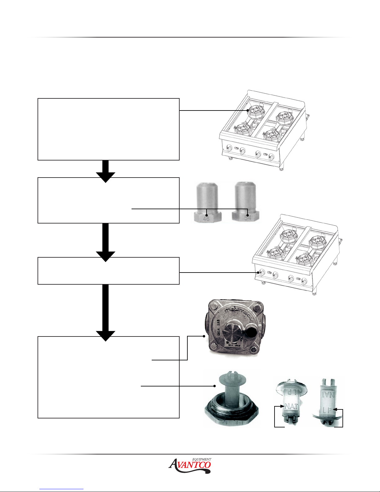
CONVERSION
Instructions are for conversion from Natural Gas to Propane (L.P.) on all models. The
conversion should be done before connecting the unit to the gas supply.
Units are shipped from the factory equipped for use on natural gas. Orifices necessary for LP
(propane) are provided in a bag tied to the valve on the front panel.
1. Remove the trivets from the top
of the appliance.
2. Remove the burner from the top
of the gas pipe.
3. Replace the orifice fittings into
the valve. Note: Unit Number on
side of orifice fittings.
4. Install the front panel knobs.
5. Before installing the regulator,
unscrew the octagonal cap,
up you can read (NAT) on the
plastic insert out of the cap, flip
it over and snap back in.
6. Continue with installation.
Orifice Fittings
Regulator with Brass Cap
Page | 6
L.P Position of Insert
Plastic Insert
 Loading...