

Page 1

Avant Mostro 700 Nitro
Assembly Manual Version 1.10
Latest Assembly Manual is located at:
http://www.AvantRC.com/Products/Mostro/n700MostroManual.pdf
Mostro
unleash the monster inside
Copyright 2014 Avant RC. All rights reserved
Page 2
Avant
Mostro
700 Nitro
LIABILITY DISCLAIMER
!
!
This kit is for a radio controlled (RC) helicopter. RC Helicopters are not toys.
Moving parts can present a hazard to operators, bystanders and anyone or
anything that could be reached by the RC helicopter. Improper operation,
maintenance or assembly can potentially cause a helicopter to pose a danger
to persons or objects including but not limited to the possibility of causing serious physical injury and even death. After leaving its facilities the manufacturer
has no way of maintaining control or supervision over the assembly and/or operation of the helicopter therefore the manufacturer and/or its agents assume
no responsibility or liability whatsoever for any damages including but not
limited to ones generated by incidental or consequential damages. The operator of the helicopter assumes all responsibility and liability that could be result
from the correct or incorrect operation of the helicopter.
This product is intended to be used by experienced adult radio control helicopter pilots under controlled safety conditions and on locations properly autho-
rized and setup for safe ying and away from other people. This product must
not be operated without reasonable Liability Insurance.
Under no circumstance should a minor be allowed to operate this or any radio
controlled helicopter without the approval, supervision and direction of his parent or legal guardian who takes full responsibility for the minor’s actions.
Do not operate an RC helicopter within the vicinity of homes, trees, electrical
lines during inclement weather or rain or near crowds of people.
Before you start assembling:
Get the latest manual: It’s highly recommended that you get the latest version
of the manual. Please download a copy by clicking below:
http://www.AvantRC.com/Products/Mostro/n700MostroManual.pdf
and use that copy instead of this one.
Page: 2 Copyright 2014-2015 Avant RC. All rights reserved
Page 3
Avant
Mostro
!
700 Nitro
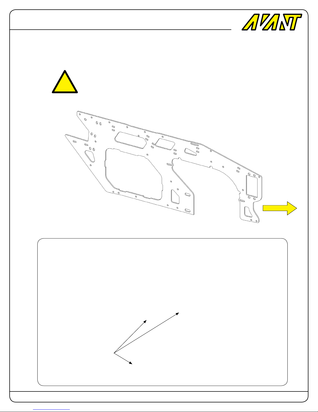
Preparation of ALL Carbon parts.
Important: Using a piece of sanding paper sand and round the edges of ALL the
carbon ber pieces.
Sharp edges can cut into the electric wires and since carbon ber is conductive
it can possibly create an electrical shortcut. Sharp edges can also cut into control and power wires creating shorts that could make the motor and or electronics
operation fail. Whenever you’re ready to install a carbon ber piece make sure to
sand all its edges to prevent wire chang and a possible electrical short circuit.
Make sure edges are
round and smooth on
ALL carbon parts not
only the frames
Sand Edges
Page: 3 Copyright 2014-2015 Avant RC. All rights reserved
Page 4
Avant
Mostro
700 Nitro
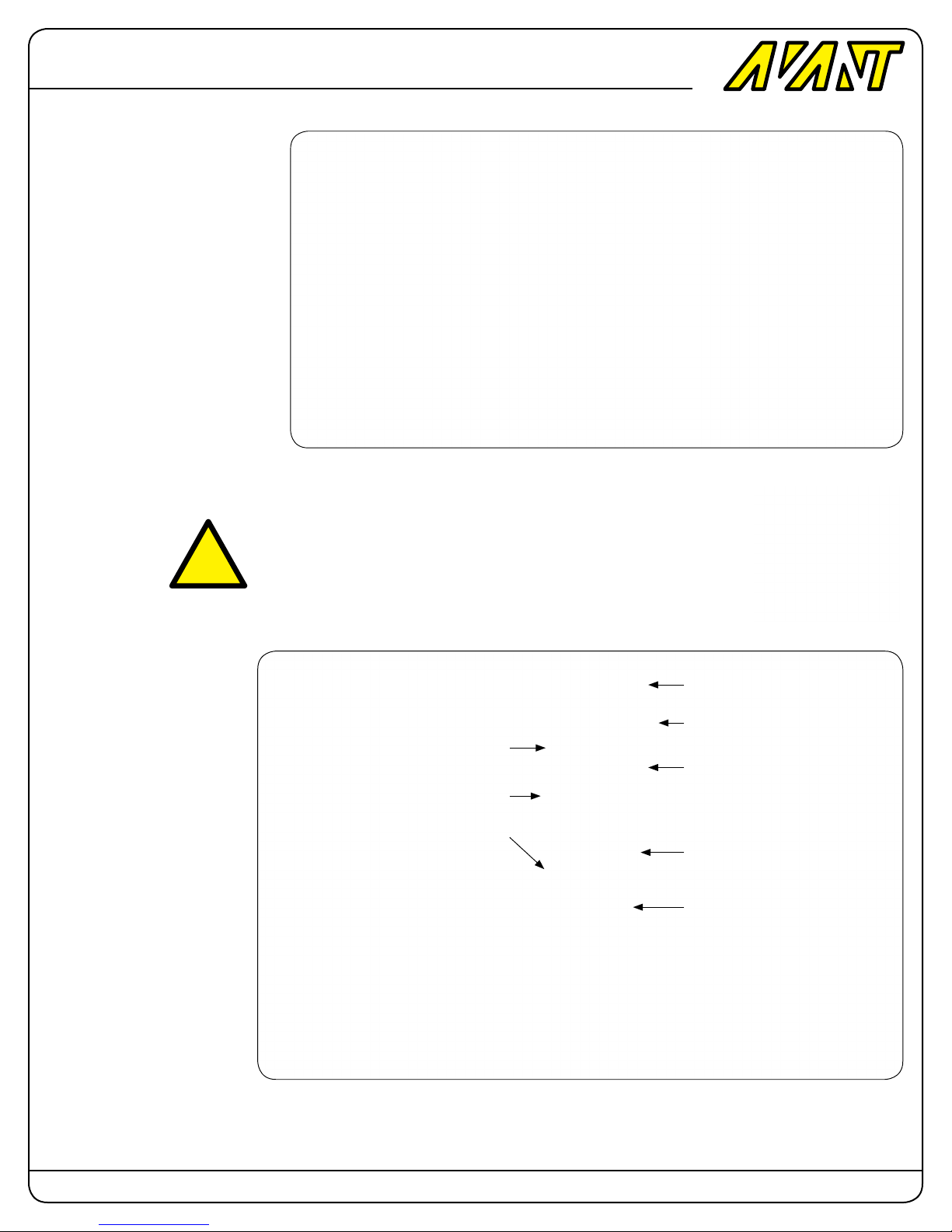
Step 1: Bottom gear plate assembly.
HARDWARE BAG CONTENTS
Qty Description
2 - M3x6mm Round Head Screw
4 - M2.5x8 or 10mm Socket Head Cap
5 - M3x6mm Socket Head Cap Screw
1 - M3x16mm Round Head Screw
1 - M3x12mm Socket Head Cap Screw
4 - M4x8mm Socket Head Cap Screw
5 - M4x10mm Socket Head Cap Screw
2 - M4x12mm Socket Head Cap Screw
1 - M4x18mm Socket Head Cap Screw
1 - M4 Locknut
1 - 10x12x1 Bearing Spacer
1 - Idler Pulley Arm Torsion Spring
!
IDLER PULLEY ARM
Attach the short post to the tensioner idler pulley Arm.
Install the idler pulley.
Install the arm stopper M3X6
screw.
Place the torsion spring inserting
one end into the bottom gears
plate.
Insert the arm into the torsion
spring.
Insert screw to hold arm in place.
Rotate the arm between the stopper screw and the bearing edge
and slide it down the screw and
then tighten the screw.
Unless directed otherwise ALWAYS USE BLUE LOCTITE
on all threads except for locknuts. Failure to do so can
make parts come lose during ight creating hazardous
and dangerous conditions.
M3x6 Button Head Screw
Tail Belt Idler Pulley
M3x16 Button Head Screw
Idler Pulley Short Post
Tail Belt Idler Pulley Arm
Torsion Spring
M3x12 Socket Head Screw
M3x6 Socket Head Arm Stopper Screw
Make sure the arm moves freely
between the stopper screw and
the bearing seat wall.
Page: 4 Copyright 2014-2015 Avant RC. All rights reserved
Page 5
Avant
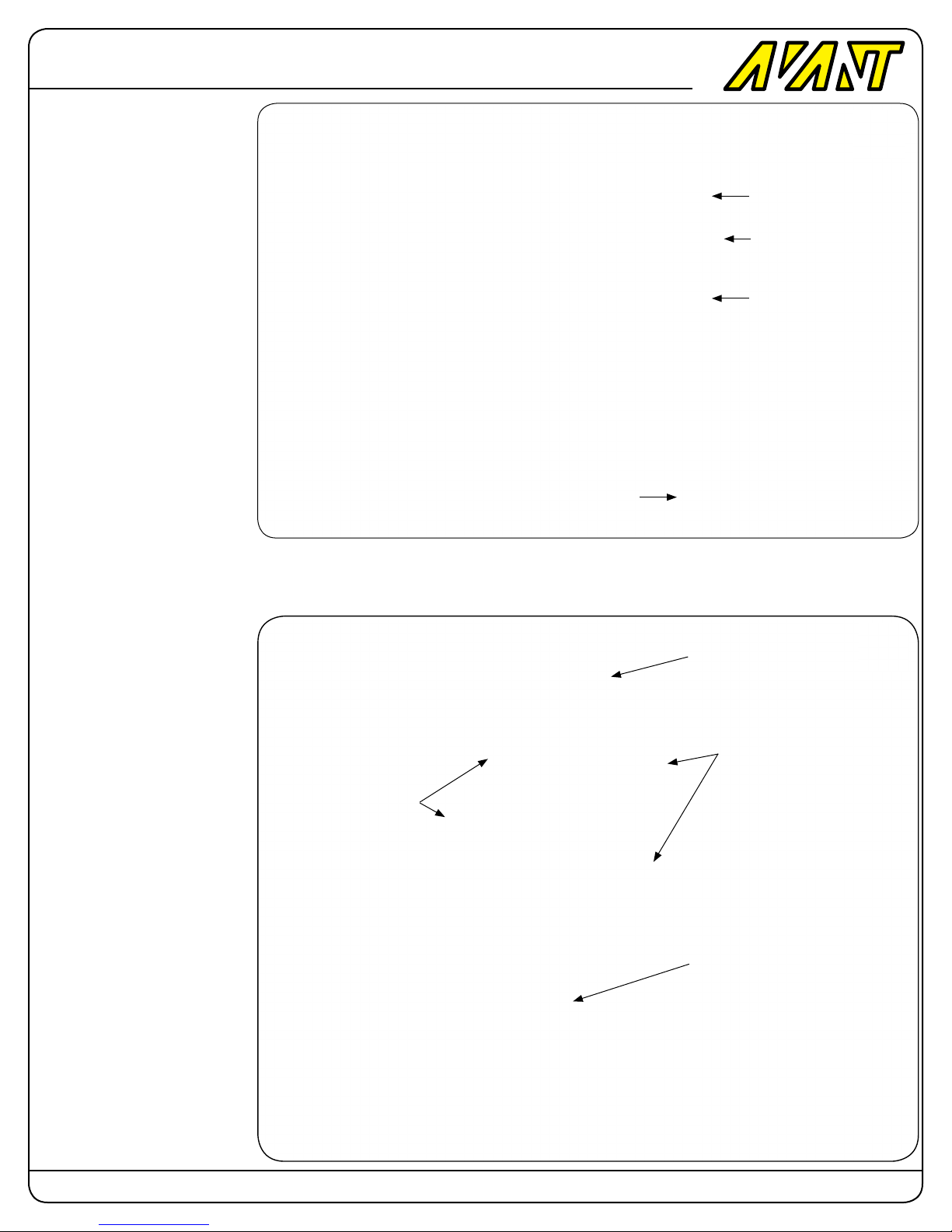
Long idler pulley post
Install the long idler pulley post
with the M4 screw.
Post in place.
Install the pulley using the M3
screw.
Mostro
700 Nitro
M3x6 Button Head Screw
Tail Belt Idler Pulley
Idler Pulley Long Post
M4x10 Socket Head Screw
CONICAL PULLEY
Install the side plate with four
M2.5x8 or 10mm socket head
cap screws.
Attach the conical pulley to the
shaft with four M3x6mm socket
head cap screws.
M2.5x8 or 10 Socket
Head Cap Screw (4)
M3x6 Socket Head Screw
M3x6 Socket Head Screw
10mm Intermediate shaft.
Page: 5 Copyright 2014-2015 Avant RC. All rights reserved
Page 6
Avant
Mostro
700 Nitro
PLATE PILLARS
Install the four Pillars as shown
using the M4 screws.
M4x8 Screw (4)
Plate Pillars (4)
MAIN ONE-WAY PULLEY
Slide the intermediate shaft into
the one-way clutch main pulley.
Notice the side that goes into
the conical pulley.
Use light oil to lubricate the
one-way bearings.
Slide the 1mm bearing spacer
onto the intermediate shaft.
37T Conical Pulley
Intermediate Shaft
61T Main One-Way Pulley
1x10x12 Bearing Spacer
Page: 6 Copyright 2014-2015 Avant RC. All rights reserved
Page 7
Avant
Mostro
700 Nitro
17T PINION
Insert the 17T helical pinion
and install the M4 screw and
locknut.
This screw needs to be tightened very hard.
!
WARNING! Make sure the top
side of the locknut is at and
parallel to the top of the pinion
otherwise there will be binding when the top servo plate is
installed.
Before you install the top servo
plate the intermediate shaft will
have lateral play. That is normal
M4 Locknut
17T Helical Pinion
Before you install
the top servo plate
this shaft will have
lateral play. That is
normal
M4x18
Boom Clamps
Install the clamps as shown but
don’t tighten the screws that
hold them against the plates
yet.
Temporarily insert the boom in
place to be used for alignment.
Lightly tight the clamps around
the booms while still allowing
the boom to rotate.
Now that the boom clamps are
aligned tighten the screws that
hold the clamps to the plate.
This guarantees that the clamps
won’t mar the boom when tightened. After this is done remove
the boom again.
M4x12 Socket Head Cap Screws (2)
M4x10 Socket Head Cap Screws (4)
Page: 7 Copyright 2014-2015 Avant RC. All rights reserved
Page 8
Avant
Mostro
700 Nitro
Step 2: Top Servo plate assembly.
HARDWARE BAG CONTENTS
Qty Description
2 - M3x6mm Round Head Screw
17 - M3x8mm Round Head Screw
4 - M3x8mm Socket Head Cap Screw
1 - M3x12mm Socket Head Cap Screw
4 - M4x8mm Socket Head Cap Screw
1 - M4x24mm Shouldered Screw
1 - M4 Locknut.
Servo posts installation
Install the Servo posts, CCPM
Guide Post and the Elevator Servo Bushing post using
the eleven M3x6 round head
screws provided.
!
It’s strongly recomended to use
a servo at this point to size the
spacing of the sliding servo
posts and centering of the servo
arm screw with pin into the
bushings.
Note: Use one of the
servos to set the location
of the sliding servo posts
as well as the center arm
screw with pin into the
bushings.
M3x8 Button Head Screw (11)
Page: 8 Copyright 2014-2015 Avant RC. All rights reserved
Page 9
Avant
Main gear assembly
Using a suitable wrench align
the gear holes and the gear hub
threaded holes and slide the
gear hub in place.
Install the six M3 screws that
hold the main gear to the gear
hub.
Mostro
700 Nitro
Installing the main shaft
Slide the main shaft into the
hub and insert the shouldered
screw in place.
Notice that the hole used here
is the one that’s farther away
from the shaft end.
M3x8 Button Head Screws (6)
M4 Locknut
M4x24 Shouldered Socket Head Cap Screw
Page: 9 Copyright 2014-2015 Avant RC. All rights reserved
Page 10

Avant
Top Servo Plate assembly
Attach the Top Servo Plate to
the Bottom pillars using four
M4X8 screws.
Mostro
700 Nitro
M4x8 Socket Head Cap Screw (4)
Main shaft collar
The collar allows the main shaft
to be held in place precisely by
sandwiching the two main shaft
bearing mounted on the plate
between the main gear hub bottom and the shaft collar.
In order to secure it even more
use blue loctite as extra insurance.
That being said the main gear
hub is also held in place securely because it’s itself sandwiched between the bottom
plate bearing and the top servo
plate bearing.
This gives redundant security
but the collar is the one that
gives precision.
Spread a drop of blue loctite
inside the collar and wipe any
excess so that it won’t contaminate the bearing.
M3x12 Socket Head Cap Screw
Note: Use Blue Loctite both
in the screw and the collar
inner wall.
Install the collar and press the
main shaft into the bearing
while pressing the collar into the
opposite bearing so that there
is no up-down play left whatsoever.
Page: 10 Copyright 2014-2015 Avant RC. All rights reserved
Page 11
Avant
Main Shaft Top Round
Bearing Block
Slide the Main shaft top round
bearing in place.
Install the four M3 socket head
cap screws.
Mostro
700 Nitro
M3x8 Socket Head Cap Screws (4)
CCPM Guide
Slide the swashplate in place
and align the CCPM guide pin
toward the front.
Install the CCPM guide carbon
plate with the M3x6m round
head screws.
Carbon Fiber CCPM Guide
M3x6 Button Head Screws (2)
Page: 11 Copyright 2014-2015 Avant RC. All rights reserved
Page 12
Avant
Mostro
700 Nitro
Step 3: Frames assembly.
HARDWARE BAG CONTENTS
Qty Description
4 - M3x20mm Round Head Screw ( Landing Geear )
4 - M4x5mm Setscrew ( Landing Gear )
1 - M4x4mm Setscrew ( Hex starter Adapter )
4 - M3x14mm Round Head Screw ( Starter Shaft Block )
1 - E-Clip ( Starter Shaft )
1 - 6mm ID x 0.3mm Spacer ( Starter Shaft )
2 - M3x16mm Round Head Screw ( Starter Shaft Block )
2 - M3 Threaded Inserts ( Canopy Screws )
4 - M2.5 Threaded Inserts ( Throttle Servo )
2 - M3 Washer ( Slider Plate )
10 - M4 Washer ( 4 Slider Plate, 4 Motor Mount, 2 RPM Sensor )
6 - M3x25mm Socket Head Cap Screw ( 4 Fan Shroud, 2 Tank
side plate )
11 - M3x8mm Socket Head Cap Screw ( 6 Fanshroud, 3 LG Mini
blocks, 2 Canopy Posts,
Middle Stiffener plate )
11 - M3x10mm Socket Head Cap Screw ( 2 Slider Plate, 9 Reinforcer Plate )
44 - M3x6mm Round Head Screw
12 - M3x8mm Round Head Screw ( Monoblock attachment )
11 - M4x8mm Socket Head Cap Screw ( 2 Clutch )
4 - M4x8mm Socket Head Cap Screw ( 4 Slider Plate )
8 - M4x14mm Socket Head Cap Screw ( 4 Engine Mounts, 4
Engine )
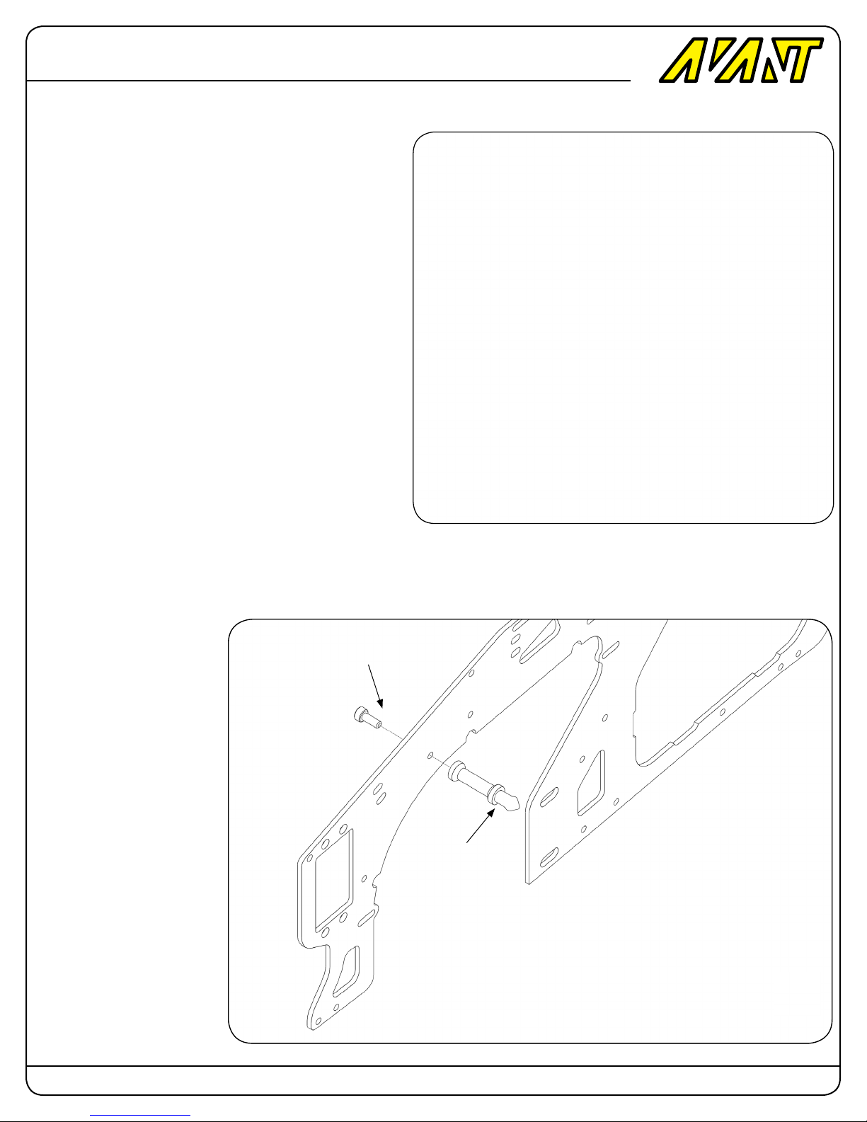
Canopy posts
Install the canopy post in place
as shown using the M3x8mm
screw.
Repeat for the other side.
M3x8 Socket Head Cap Screw
Canopy Post
Page: 12 Copyright 2014-2015 Avant RC. All rights reserved
Page 13
Avant
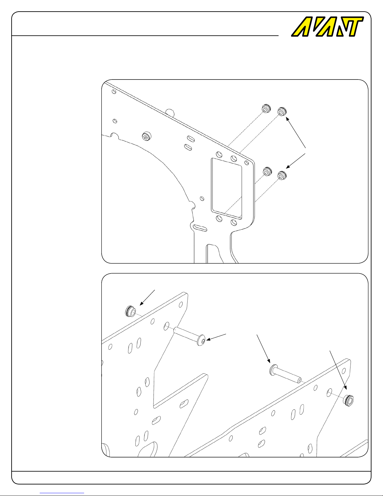
M2.5 Threaded inserts
In the holes indicated place four
M2.5 threaded inserts on the
outside of the left frame and using an M2.5 and an M3 washer
insert the extra M2.5x8mm
socket head cap screw in place.
Mostro
700 Nitro
Once it’s in place use a wrench
and tighten it making them be
press-tted into place. Once in
place remove the screw and
washer. The insert is now in
place. Repeat for the remaining
inserts.
M3 Threaded inserts
In the holes indicated place
an M3 threaded insert on the
outside of the frames and insert
an M3x16 Round head screw.
Once it’s in place use a wrench
and tighten it making the insert
be press-tted into place.
M2.5 Threaded Inserts (4)
M3 Threaded Insert
M3x16 Round Head Screw (2)
M3 Threaded Insert
Page: 13 Copyright 2014-2015 Avant RC. All rights reserved
Page 14
Avant
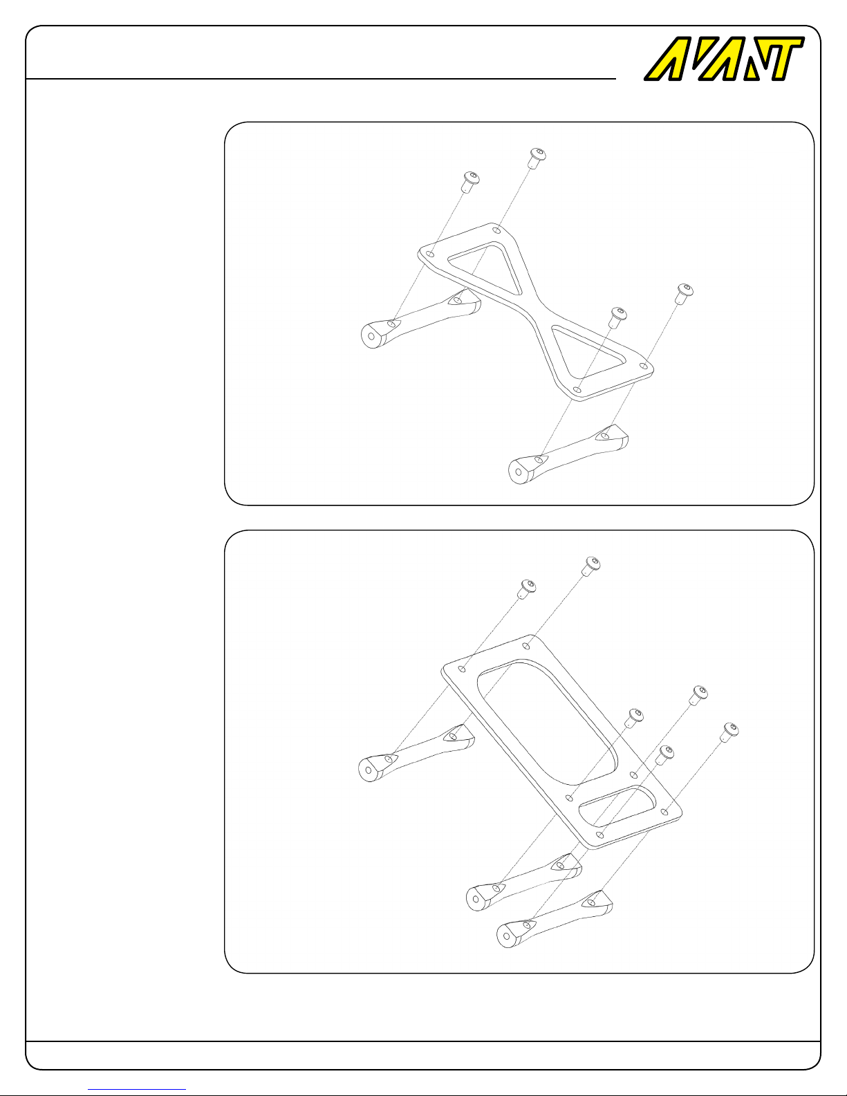
Front Stiffener Plate
Mostro
700 Nitro
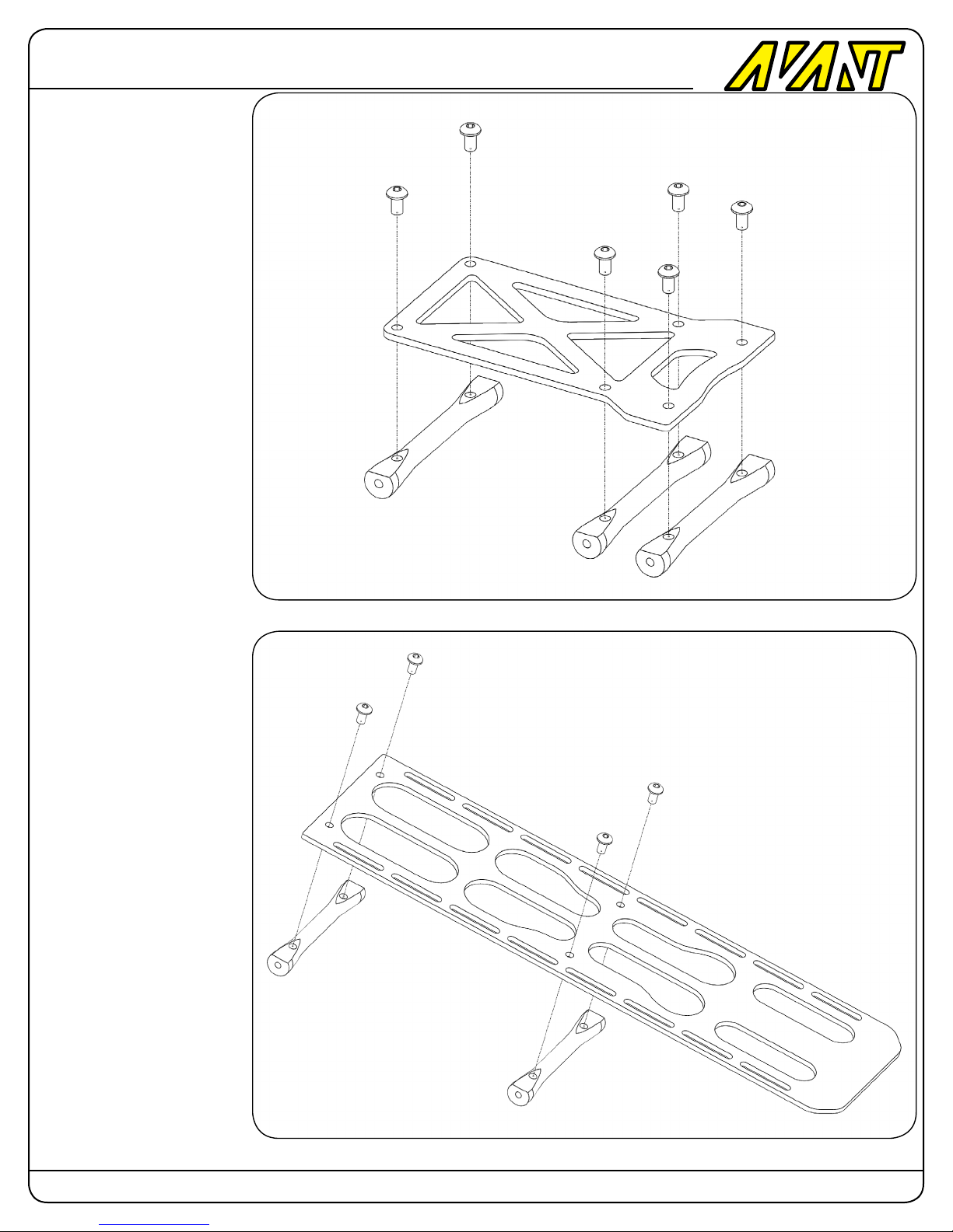
Install the support spacers using four M3x6mm round head
screws as shown.
Middle Stiffener Plate
M3x6 Round Head Screw (4)
Support Spacers (2)
Install the support spacers
using six M3x6mm round head
screws as shown.
M3x6 Round Head Screw (6)
Support Spacers (3)
Page: 14 Copyright 2014-2015 Avant RC. All rights reserved
Page 15
Avant
Bottom Stiffener Plate
Install the support spacers
using six M3x6mm round head
screws as shown.
Mostro
700 Nitro
M3x6 Round Head Screw (6)
Support Spacers (3)
Battery Plate
Install the support spacers using four M3x6mm round head
screws as shown.
M3x6 Round Head Screw (6)
Support Spacers (2)
Page: 15 Copyright 2014-2015 Avant RC. All rights reserved
Page 16
Avant
Mostro
700 Nitro
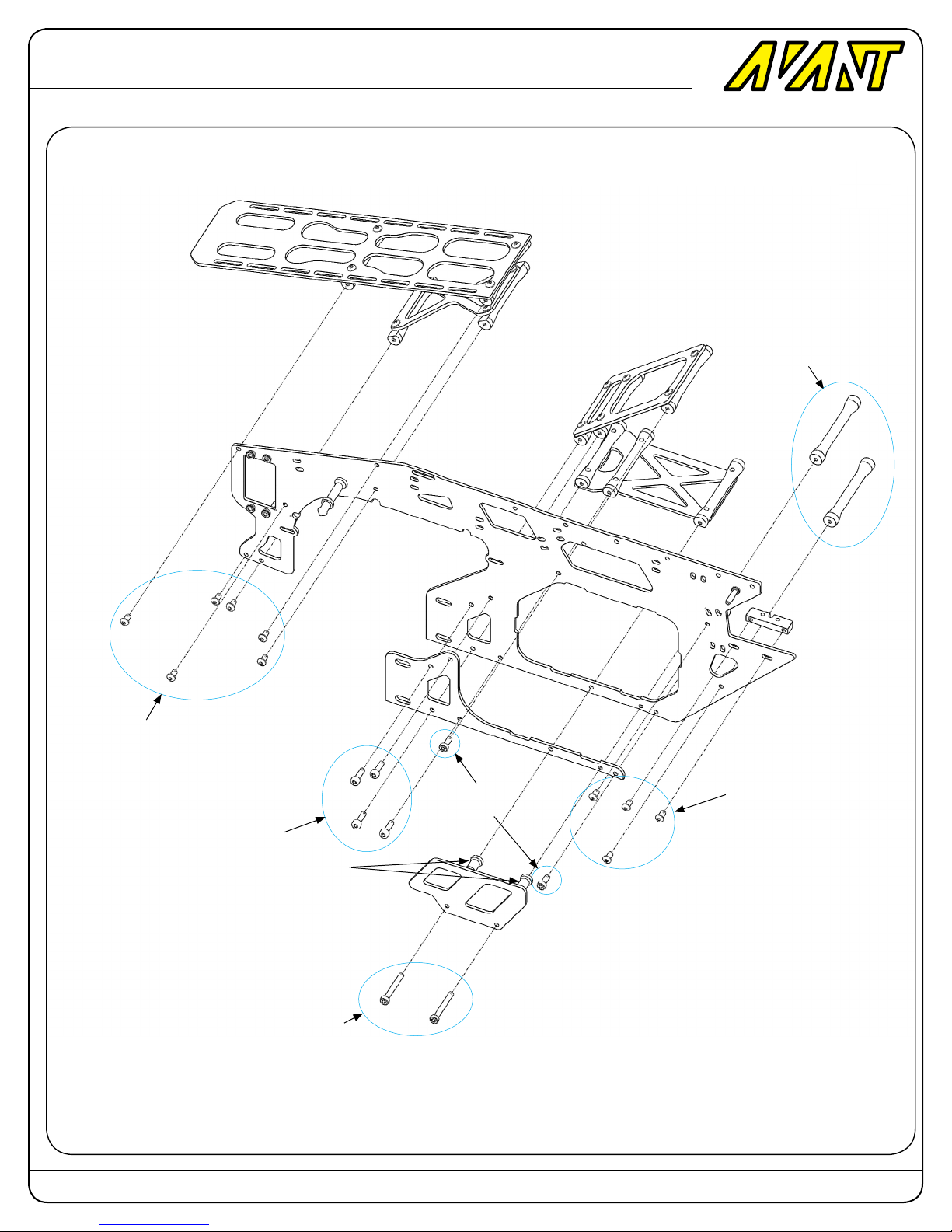
60mm frames spacers (2)
M3x6 Button Head Screw (6)
M3x10 Socket Head Cap Screws (4)
13.5mm Spacers (2)
M3x25 Socket Head Cap Screws (2)
M3x8 Socket Head
Cap Screws (2)
Left Frame assembly
Install the screws as indicated in this diagram.
Use Blue Loctite # 242 to secure all screws in place.
M3x6 Button Head Screw (2)
Page: 16 Copyright 2014-2015 Avant RC. All rights reserved
Page 17
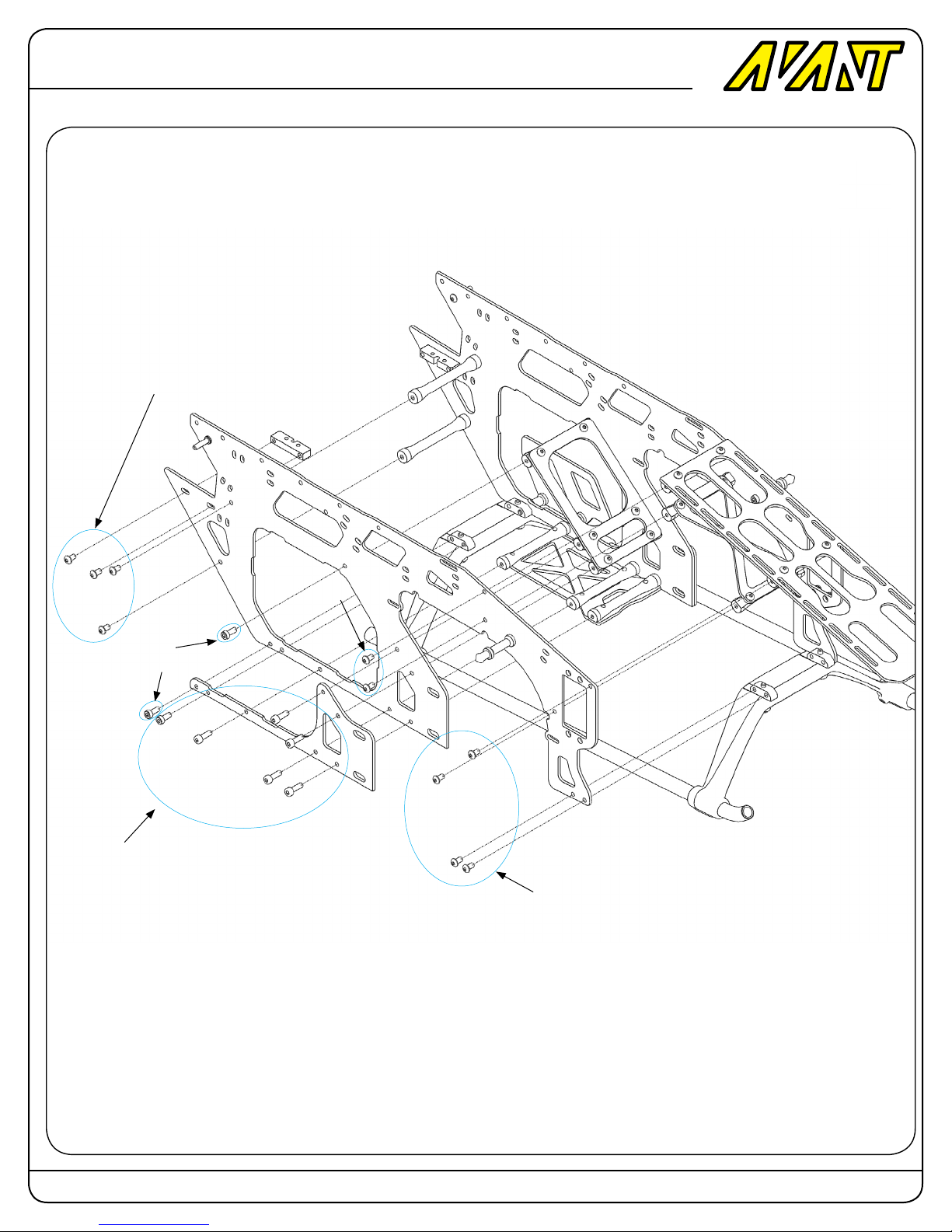
Avant
M3x6 Button Head Screw (4)
Mostro
700 Nitro
M3x8 Socket Head
Cap Screws (2)
M3x10 Socket Head Cap Screws (6)
M3x6 Button
Head Screw (2)
M3x6 Button Head Screw (4)
Right Frame assembly
Install the screws as indicated in this diagram.
Use Blue Loctite # 242 to secure all screws in place.
Page: 17 Copyright 2014-2015 Avant RC. All rights reserved
Page 18
Avant
Mostro
700 Nitro
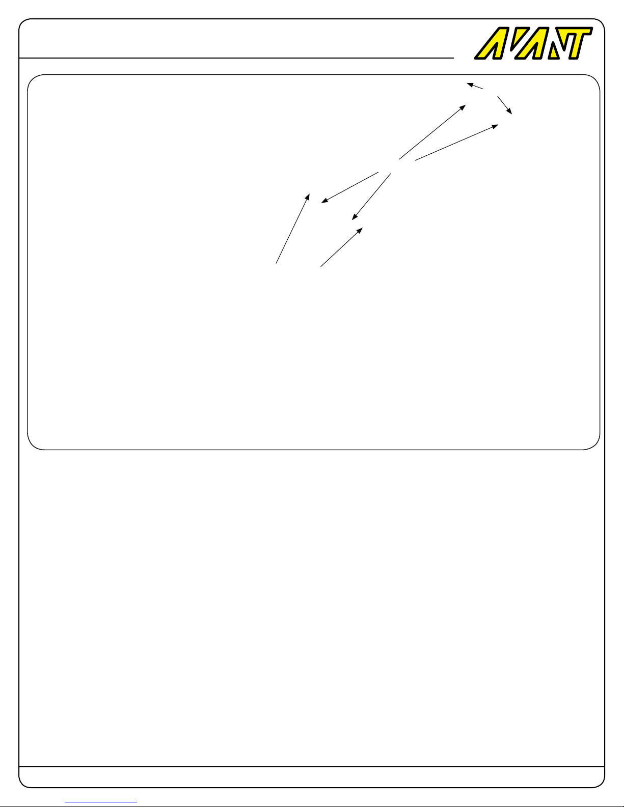
M4x5 Setscrews (2)
M3x20 Button Head Screw
M4x5 Setscrews (2)
Landing Gear
Install the landing gear with the M3x20mm round head screws.
Slide the landing skids in place and secure them with four M4 setcrews.
Page: 18 Copyright 2014-2015 Avant RC. All rights reserved
Page 19
Avant
Clutch Stack Assembly.
1) Glue the liner to the Clutch Bell using
30 minute epoxy glue. Make sure both the
liner and the bell are coated with epoxy.
Press in place and clean any excess glue
with Alcohol before it cures and keep
pressure outwards around the liner until
it’s cured.
2) Using Green Loctite secure one of the
10x19 Bearings inside the sliding block.
3) Insert the hollow shaft with the longer
thread downwards toward the clutch bell.
4) Using Green Loctite secure the second
10x19 Bearings inside the sliding block
making sure it makes the hollow shaft not
have play in between the bearings.
5) Using blue loctite screw the Motor Pulley in place onto the Clutch bell.
Mostro
700 Nitro
5) Using blue loctite Screw the hollow
shaft top nut in place by hand and then
screw the pulley-bell in place by hand.
Use a wrench to hold the top nut and
tighten the clutch bell tight.
6) Install the bearing spacer and the c-clip
in the starter shaft and slide into the bottom of the bell.
7) Using blue loctite install the top bearing
bock using the four m3x14 button head
screws.
8) Install the Hex adapter with the M4
setscrew.
Use Epoxy GLue for Liner
Page: 19 Copyright 2014-2015 Avant RC. All rights reserved
Page 20
Avant
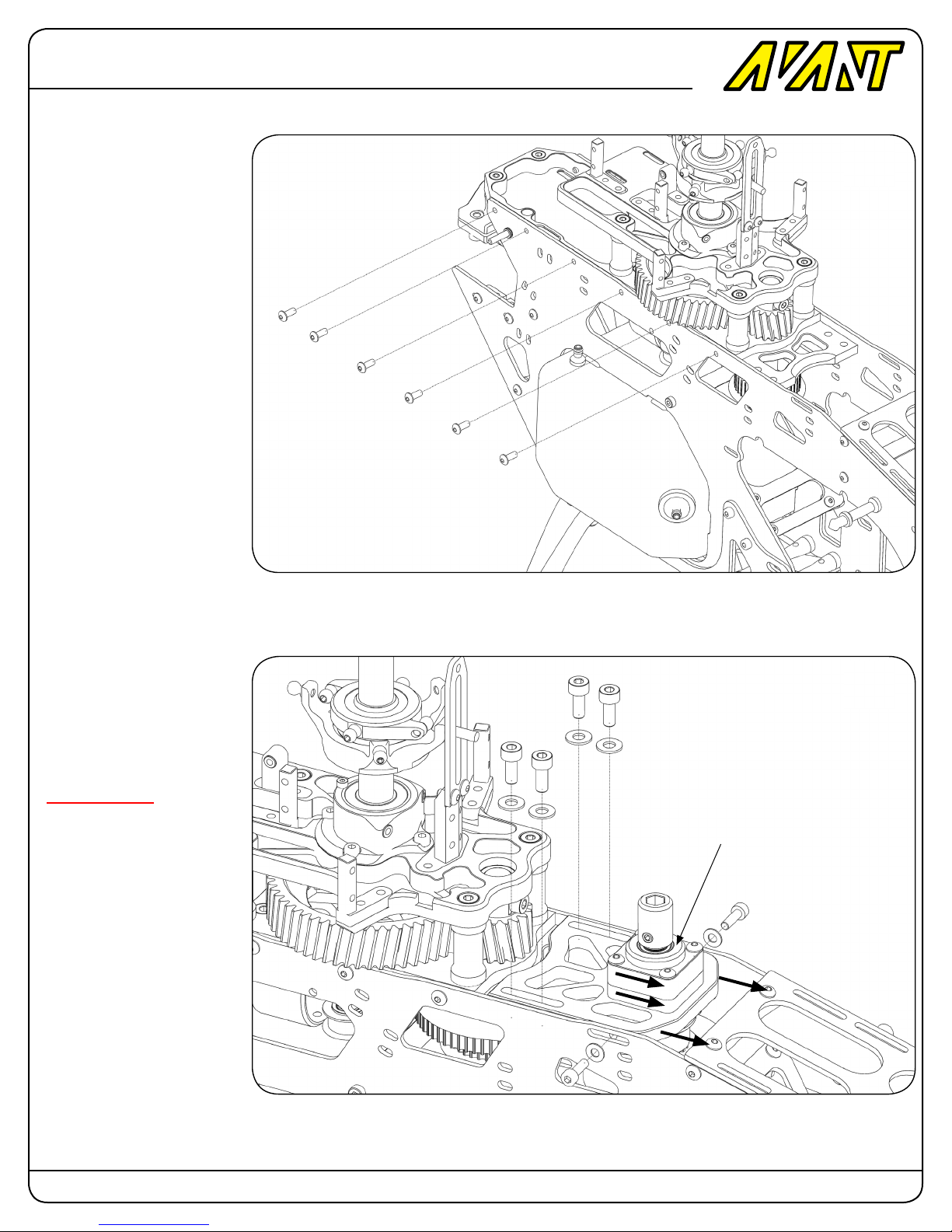
Installation of the Monoblock into the frames
Right Frame
Using six M3x8mm round head
screws afx the left frame to
the Monoblock as seen in this
picture.
Install also the M3x10 Screw
and washer to the Sliding Motor
Plate but do not tighten it yet.
Left Frame
Repeat the above procedure for
the right frame.
Mostro
700 Nitro
M3x8 Button Head Screws (6)
Sliding Stack Plate Tightening
Loosen the four M4x10 screws
that hold the motor sliding plate.
Pull the motor forward tightly
with your hands and tighten
the M3x10 sliding plate side
screws.
After those are tight then tighten
the four M4 screws on the top.
IMPORTANT NOTE
Do not use any tools to wedge
in between the gears plate and
the sliding plate to increase the
tension of the belt. In the case
of Nitro engines there is no
need and it will make the sliding
plate bearings break prematurely which is not covered by
the warranty.
M4x10 Socket Head Cap Screws (4)
M4 Washers (4)
Pull sliding plate forward with your hands
to tighten the belt. Make it hand tight.
Do not use tools to make it too tight.
M3x10 Socket Head Cap
Screws (2)
M3 Washers (2)
Page: 20 Copyright 2014-2015 Avant RC. All rights reserved
Page 21
Avant
Mostro
700 Nitro
Fan, Fanshroud, Fan hub and
Clutch installation.
1) Make sure that the polarity of the magnet is correct by checking that the magnet
triggers the sensor when passed next to it.
Using Epoxy glue the RPM Sensor magnet in one of the round holes designed for
them in the bottom of the fan. Install the
Fan in the Fanhub with four M3x6 Round
Head screws.
2) Screw the fan hub into the engine making sure the engine crankshaft is locked in
place with an engine lock then install the
engine nut and tighten it in place.
3) Using two M4x8 Socket head cap
screws install the clutch in place.
4) Fanshroud
4.1) Cut the necessary opening for the
pipe you’re using in the fanshroud.
4.2) If needed enlarge the carburetor hole
to make yours t the fanshroud.
4.3) Cut the opening for the RPM sensor.
4.4) Join the fanshroud halves using six
M3x8mm Socket Head Cap screws.
M4x8 Socket Head Cap Screws (2)
M3x6 Round Head Screws (6)
Sensor Cutout
Pipe Header
Cutout
M3x8 Socket Head Cap Screws (6)
Page: 21 Copyright 2014-2015 Avant RC. All rights reserved
Page 22
Avant
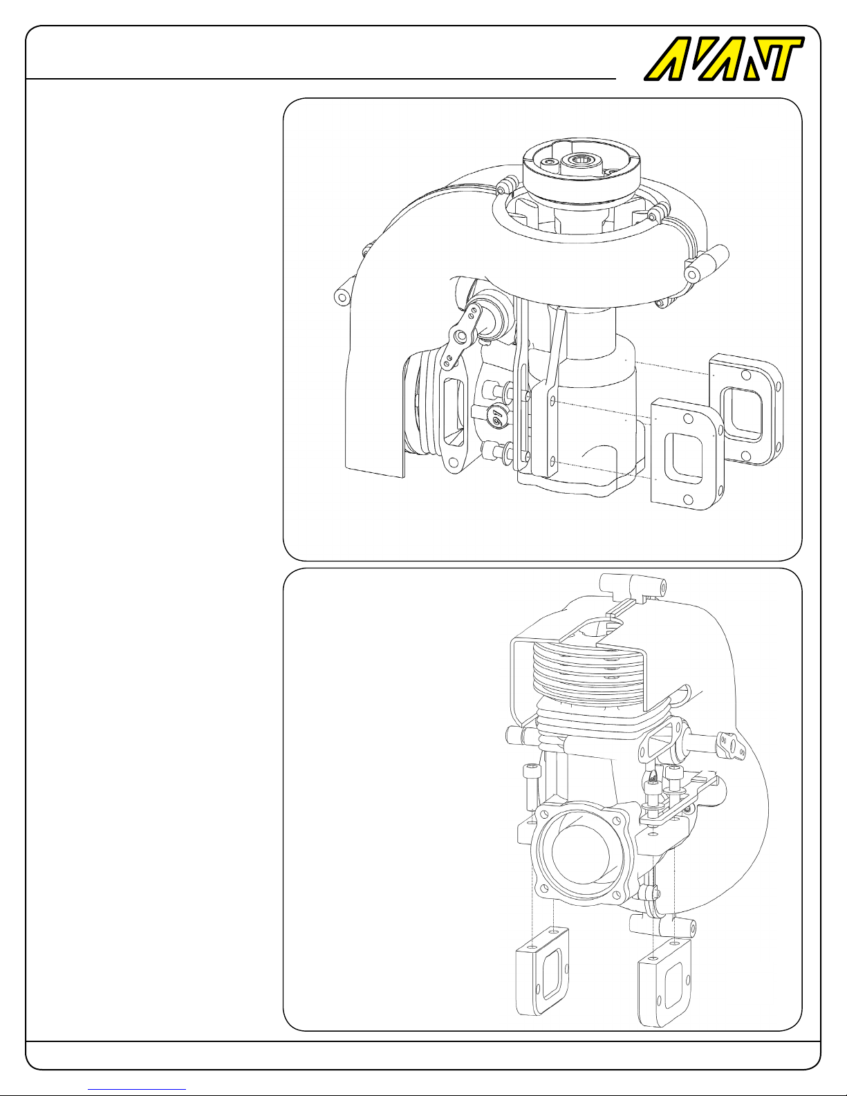
Fan, Fanshroud, Fan hub and
Clutch installation (Continuation).
4) Fanshroud
4.1) Cut the necessary opening for the
pipe you’re using in the fanshroud.
4.2) If needed enlarge the carburetor
hole to make yours t the fanshroud.
4.3) Cut the opening for the RPM sensor.
4.4) Join the fanshroud halves using six M3x8mm Socket Head Cap
screws.
5) Install the M4x14 Screws to secure
the engine to the engine mount on one
side and M4x14 Screws and Washers
to install the RPM sensor on the other
side.
Mostro
700 Nitro
M4x14 Socket Head Cap Screws (4)
M4x14 Socket Head Cap Screws (4)
Page: 22 Copyright 2014-2015 Avant RC. All rights reserved
Page 23
Avant
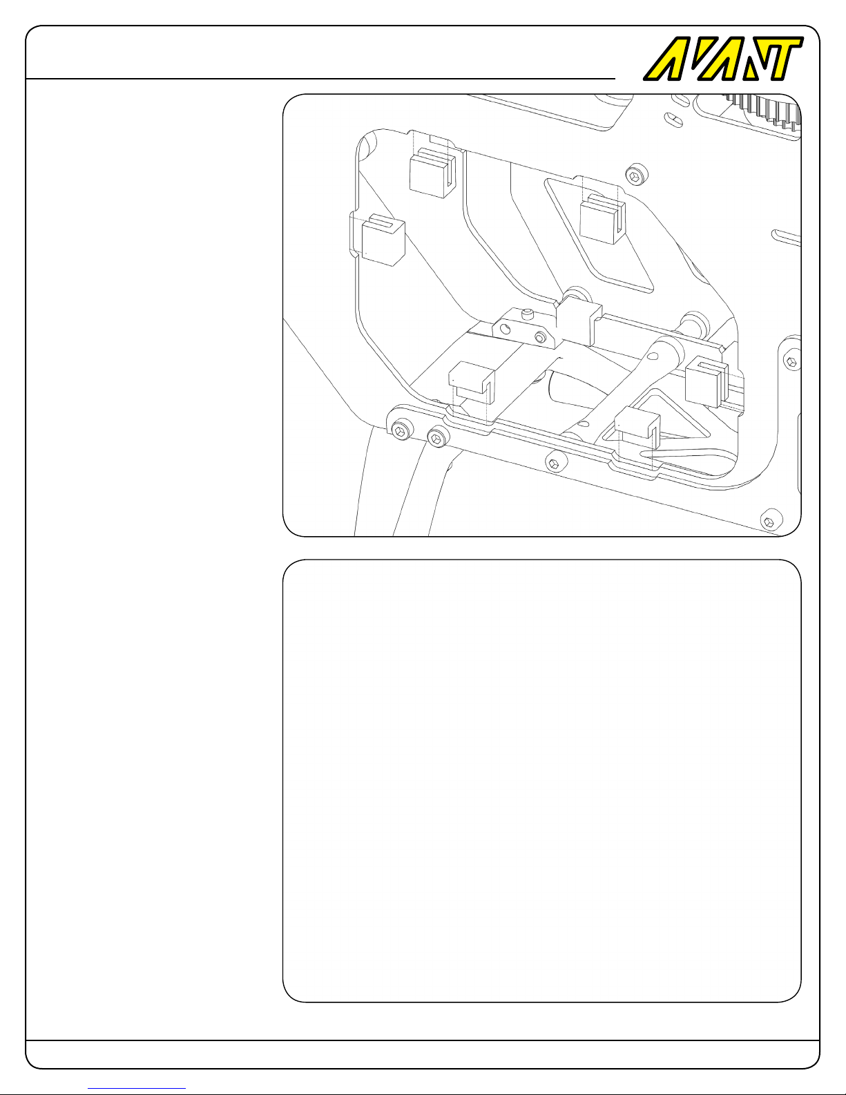
Tank Rubber Supports
1) Cut the supplied rubber strip into
twelve 10mm long U-Shaped rubber
supports as indicated.
2) Cut one side of the bottom ones
shorter as indicated. You will also need
to cut a corner in the ones that touch
the landing gear mini-blocks to make
them t.
3) Use CA Glue (Cyanoacrilate or
crazy glue) to install the rubber supports into the frames.
Mostro
700 Nitro
Tank Assembly
1) Drill a 1/8” hole (3mm) on the top
vent hole of the tank and screw the
vent tting with the o-ring in place.
There is no need to tap a thread. The
metal thread from the tting will thread
itself into the plastic hole.
2) Assemble the fuel line and cluck
and double the tube line on the ends
to prevent it from coming lose.
3) Insert the rubber grommets in
place and then slide the line and tank
stopped plug in place.
U-Shaped Rubber Tank Supports Tank (12)
Page: 23 Copyright 2014-2015 Avant RC. All rights reserved
Page 24
Avant
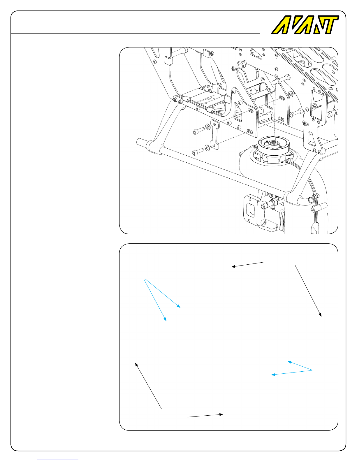
Engine placement
Insert the engine clutch one-way bearing into the starter shaft.
Lock the engine and insert a 6mm allen wrench in the started hex adapter
and engage the one-way bearing to
make the engine align with the starter
shaft.
After they align and the starter shaft
rolls freely tighten the four M4x14 motor mount screws to secure the engine.
Mostro
700 Nitro
M4x14 Socket Head Cap Screws (4)
M4 Washers (4)
Fan Shroud installation
Install the fan shroud by using four
17mm spacers and four M3x25mm
Socket Head Cap Screws as shown in
the picture. Do not fully tighten yet.
Once installed slide the fan shroud
assembly forward or backward to
make center the bottom round circle
with the motor fan bottom making them
concentric and ensuring the fan rotates
freely with no rubbing. Once that
location is found tighten the screws to
secure the fan shroud in place.
17mm
Spacer (2)
M3x25 Socket head
cap screw
M3x25 Socket head
cap screw
17mm
Spacer (2)
Simplied view. Engine and other
components not shown for clarity.
Page: 24 Copyright 2014-2015 Avant RC. All rights reserved
Page 25
Avant
Mostro
700 Nitro
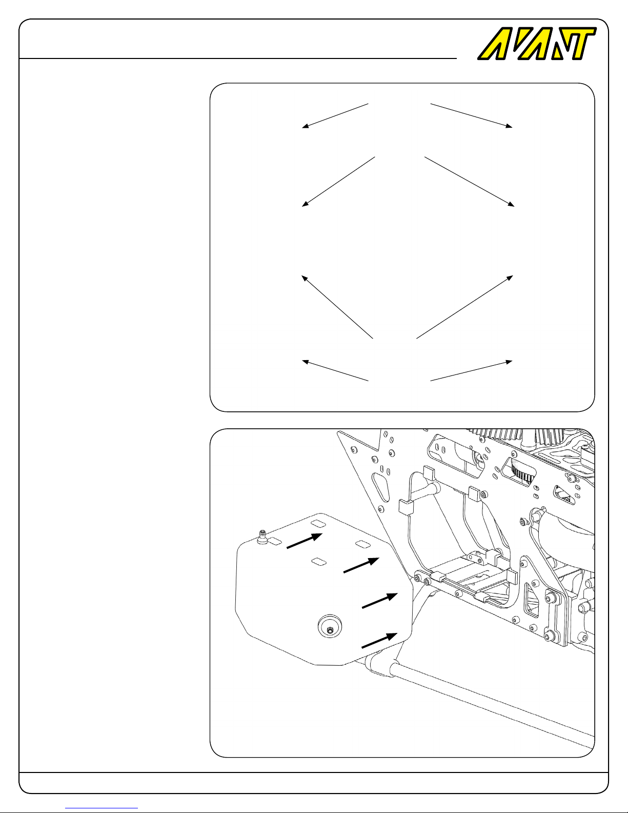
Fan Shroud installation top
view
Es explained in the previous paragraph here’s a top view of the fan
shroud installatio.
Install the fan shroud by using four
17mm spacers and four M3x25mm
Socket Head Cap Screws as shown in
the picture. Do not fully tighten yet.
Once installed slide the fan shroud
assembly forward or backward to
make center the bottom round circle
with the motor fan bottom making them
concentric and ensuring the fan rotates
freely with no rubbing. Once that
location is found tighten the screws to
secure the fan shroud in place.
Simplied view.
Engine and other components
not shown for
clarity.
M3x25 Socket head
cap screw
17mm
Spacer (2)
17mm
Spacer (2)
M3x25 Socket head
cap screw
Tank installation
Slide the tank in place going over and
under the rubber supports. You might
need to squeeze the tank a bit to make
it slide into place.
After installed and tested take it off
again so you can access the bottom of
the mechanics when you install the tail
boom in place.
Page: 25 Copyright 2014-2015 Avant RC. All rights reserved
Page 26
Avant
Mostro
700 Nitro
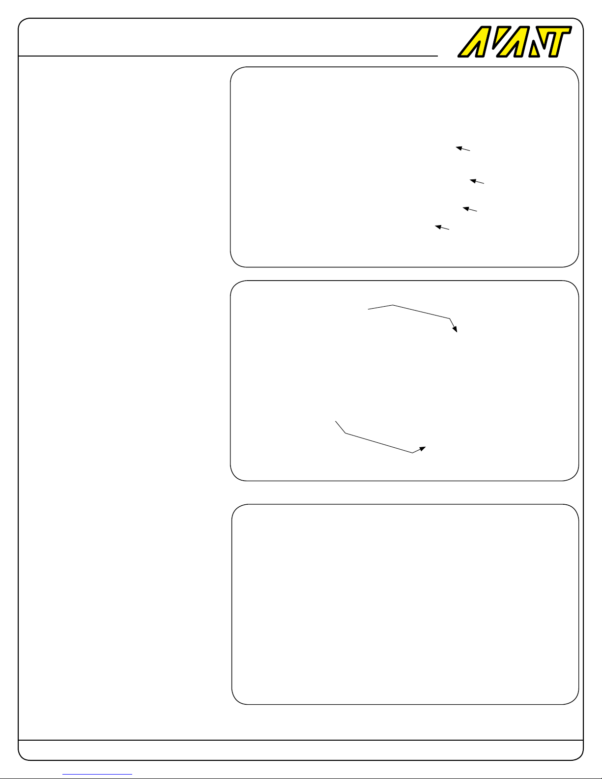
Step 4: Head
Preparation of the RigidCore Dampeners
Insert the small O-Ring into the front circular
groove.
Note:The inner dampener O-Ring is used only
if you want pre-loading of the grips or if you feel
they’re too lose. On the other hand if you feel it’s
too tight or don’t like using pre-loading there is
no need to install it. There is really no difference
performance wise.
Slide the large O-Ring around the dampener until
the outside groove is reached.
Completed RigidCore Dampener
Page: 26 Copyright 2014-2015 Avant RC. All rights reserved
Page 27
Avant
HARDWARE BAG CONTENTS
Mostro
700 Nitro
Qty Description
2 - M3x8mm Round Head Screw
2 - M3x10mm Socket Head Cap Screw
2 - M3x12mm Socket Head Cap Screw
2 - M3x14mm Socket Head Cap Screw
2 - M6x16mm Socket Head Cap Screw
1 - M4x24mm Shouldered Screw
2 - M3 Washer
2 - M6 Washer
1 - M4 Locknut.
2 - 16mm OD x 1mm Bearing Spacer
2 - 18mm OD x 10mm ID Thrust Bearing
4 - M5 ID Stainless Steel Blade Bushing
2 - M5 Alloy Steel Shouldered Blade Bolts
2 - M5 Locknuts
2 - M2.6x16mm threaded rods
2 - Thick Ball Links
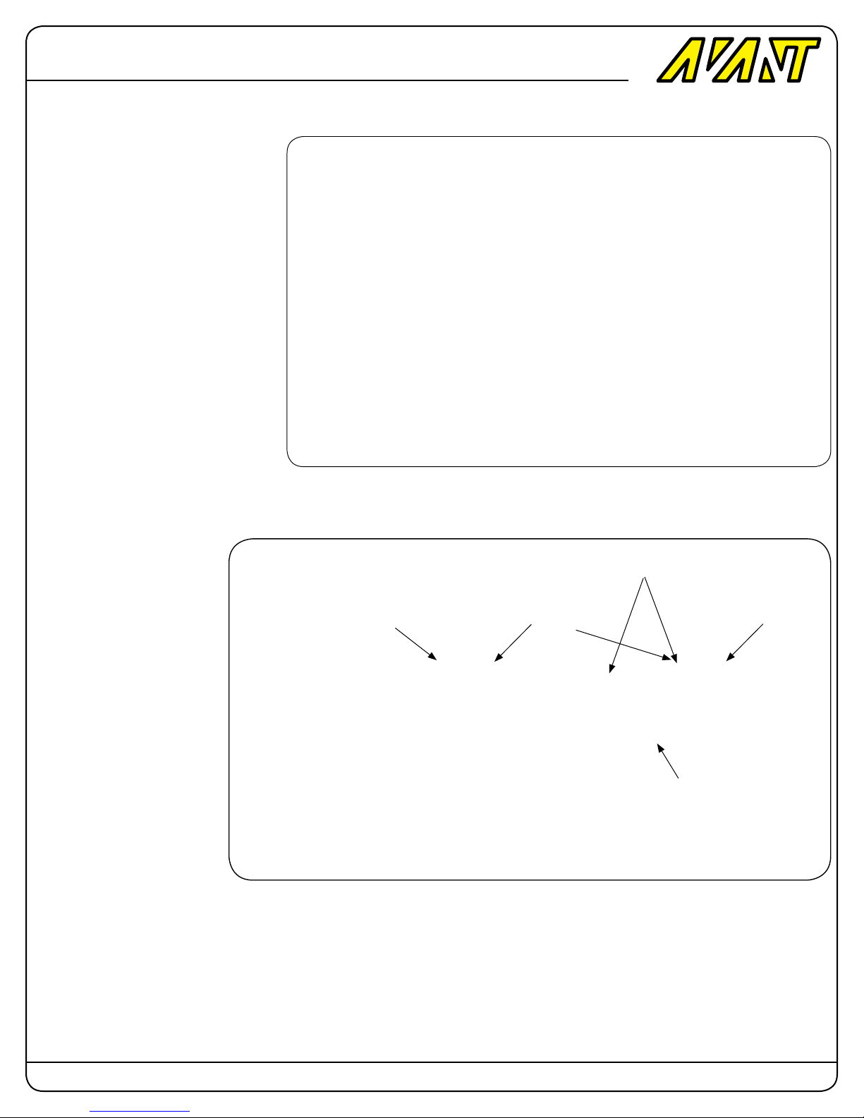
Spindle and Dampeners
DFC RigidCore Head
Use grease in the cavity
and around the dampener
Install the dampeners in the
orientation shown in the picture.
Slide the spindle into the dampeners.
Round EdgeChamfered Edge Chamfered Edge
Optional Pre-Loading O-Ring
You can watch a video on how to install and how to remove the dampeners here:
Insertion: http://www.AvantRC.com/Products/Mostro/DampenerInsertion.html
Extraction: http://www.AvantRC.com/Products/Mostro/DampenerExtraction.html
Page: 27 Copyright 2014-2015 Avant RC. All rights reserved
Page 28
Avant
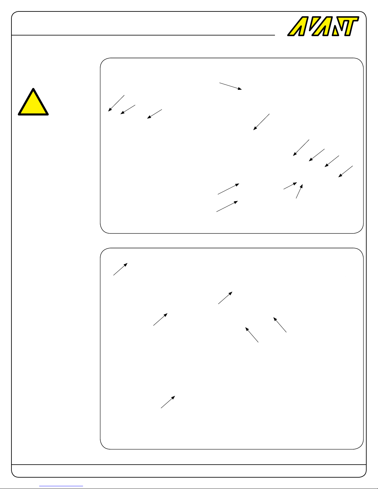
Blade grip
!
Mostro
700 Nitro
10mm Spindle
Optional Pre-Loading O-Ring
RigidCore Dampener
M5 Blade bolt
Blade Bushing
Pay attention to the correct
way to set Thrust bearing inner
diameters.
The larger ID race needs to
go rst into the spindle. The
smaller ID race goes next to the
M6 Washer.
M3x8 Round
Head Screw
Blade Bushing
M5 Locknut
16mm OD x 1mm
Bearing Spacer
Thrust Bearing
M6 Washer
M6x16
Large ID Race
Small ID Race
M3 Threaded Rod
DFC Axle
M3x10 Screw
M3x14 Screw
M2.6 Threaded Rod
Page: 28 Copyright 2014-2015 Avant RC. All rights reserved
Page 29
Avant
Mostro
700 Nitro
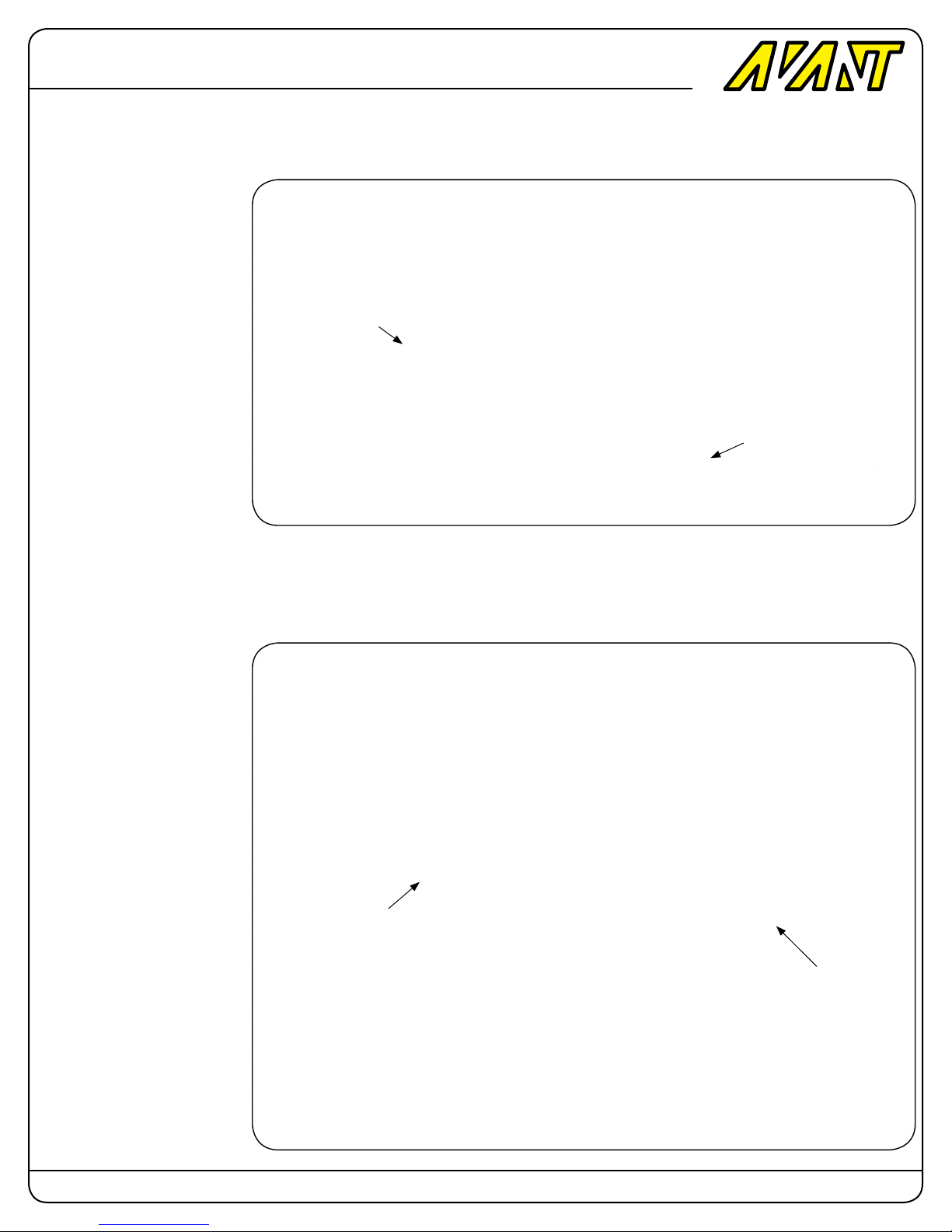
M3x12 Screw
M3x12 Screw
M4 Locknut
M4x24 Shouldered Screw
Page: 29 Copyright 2014-2015 Avant RC. All rights reserved
Page 30
Avant
HARDWARE BAG CONTENTS
Mostro
700 Nitro
Qty Description
2 - M3x10mm Socket Head Cap Screw
2 - M3x12mm Socket Head Cap Screw
2 - M3x14mm Socket Head Cap Screw
2 - M6x16mm Socket Head Cap Screw
1 - M4x24mm Shouldered Screw
2 - M6 Washer
1 - M4 Locknut.
2 - 16mm OD x 1mm Bearing Spacer
2 - 18mm OD x 10mm ID Thrust Bearing
4 - M5 ID Stainless Steel Blade Bushing
2 - M5 Alloy Steel Shouldered Blade Bolts
2 - M5 Locknuts
2 - M3x16 Round Head Screw
4 - Thick Ball Links
2 - 60mm Turnbuckle Rods.
2 - 2mm pins
2 - Y-Links
2 - Follower Arms with bearings
4 - M3 Balls
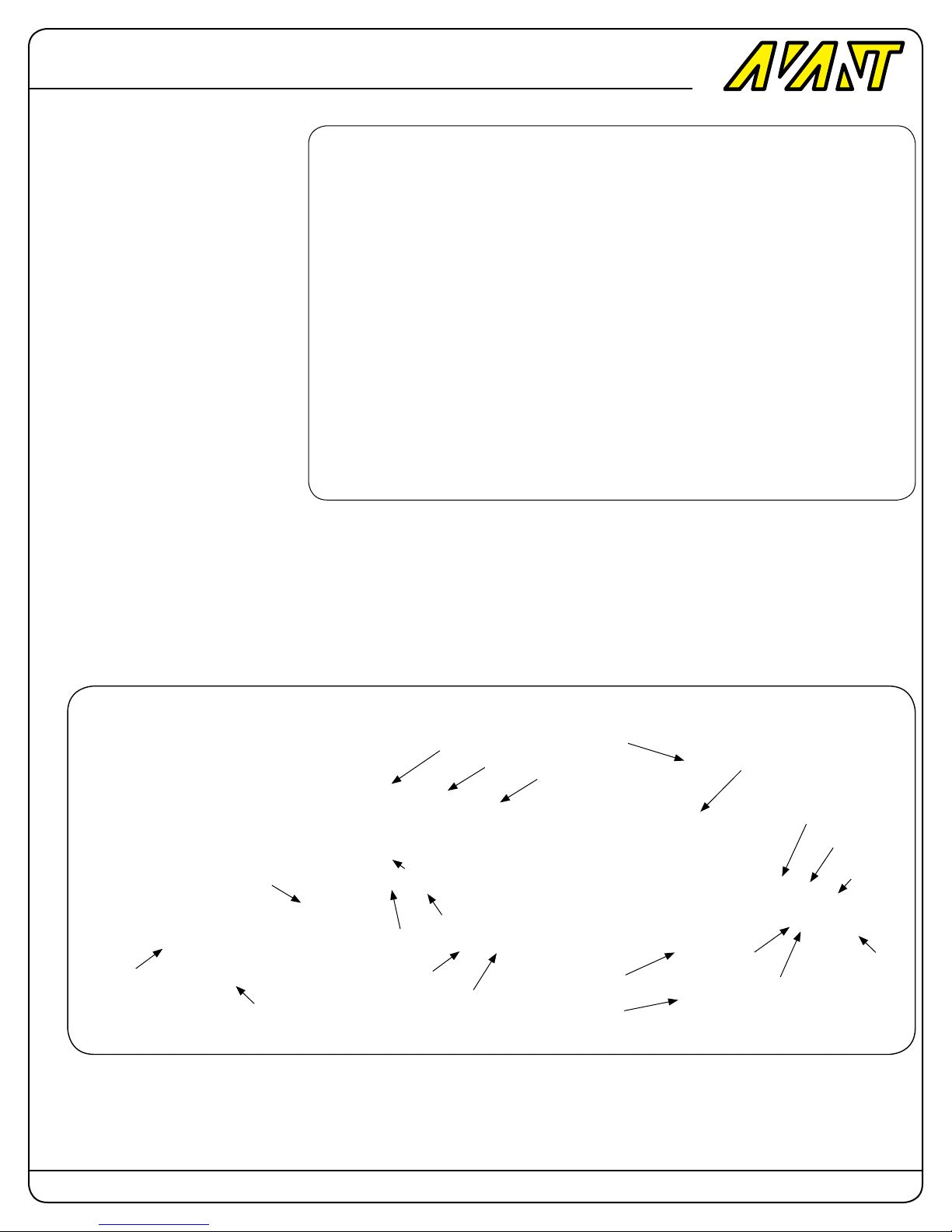
Follower Arms RigidCore Head
2mm Pin
1mm Spacer
M3x16 Round Head Screw
M4X25 Shouldered
Screw
M3 Ball
M3x12 Screw
M3x14 Screw
M3x10 Screw
10mm Spindle
Optional Pre-Loading O-Ring
Note:The inner dampener O-Ring is used only
if you want pre-loading of the grips or if you feel
it’s too lose. If you feel it’s too tight or don’t like
using pre-loading there is no need to install it.
M5 Blade bolt
RigidCore Dampener
Blade Bushing
M5 Locknut
Blade Bushing
Large ID Race
Small ID Race
16mm OD x 1mm
Bearing Spacer
Thrust Bearing
M6 Washer
M6x16
Page: 30 Copyright 2014-2015 Avant RC. All rights reserved
Page 31
Avant
Blade grip
Mostro
!
Pay attention to the correct
way to set Thrust bearing inner
diameters.
The larger ID race needs to
go rst into the spindle. The
smaller ID race goes next to the
M6 Washer.
700 Nitro
Even though it’s not shown in
this picture it’s normal and expected for the washout arms to
be pointing slightly down when
the blades are at zero pitch.
Large ID Race
Small ID Race
Page: 31 Copyright 2014-2015 Avant RC. All rights reserved
Page 32
Avant
Mostro
Step 5: Tail assembly.
HARDWARE BAG CONTENTS
Qty Description
3 - M3x6mm Round Head Screw
3 - M3x8mm Round Head Screw
2 - M3x10mm Round Head Screw
1 - M3x16mm Round Head Screw
2 - M3x8mm Socket Head Cap Screw
2 - M3x20mm Socket Head Cap Screw
2 - M3 Washer
2 - M3 Locknut
2 - M3x4mm Setscrew
1 - M4x4mm Setscrew
1 - 2mmx12mm Pin
2 - 10mm OD x 0.3 Bearing Spacer
2 - 3mm ID x 1mm Bearing Spacer
2 - 10mm OD x 5mm ID Thrust Bearing
3 - M2 Balls
Parts that might be already installed in the
boom:
1 - M2.5x8mm Socket Head Cap Screw
1 - M2.5 Washer
700 Nitro
Parts that might be already installed in the
Tail Slider
2 - 2mmx10mm Pin
1 - M3 Ball
Tail Pitch Slider
Assembly
Install the M3 ball into the tail
slider.
Insert the tail output shaft into
the brass slider sleeve then the
tail slider and the plastic tail
yoke.
Using the 2mm pins install the
tail links in place as shown.
2mm x10mm Pin
Output Shaft
M3 Ball
Slider’s Brass Sleeve
Bearing
Tail Slider
Bearing
Tail Yoke
Tail Link
2mm x10mm Pin
Page: 32 Copyright 2014-2015 Avant RC. All rights reserved
Page 33
Avant
Tail yoke Insertion
Using either a small vise or a
set of pliers insert the output
shaft into the sleeve and slider
and the hold the end of the
slider brass sleeve while screwing in the tail yoke.
Mostro
!
Warning. Tighten only up to
the point where the slider wont
have any play. Don’t overtighten the yoke into the sleeve
because the bearings will bind
and the slider won’t operate
correctly.
700 Nitro
Tail Pulley
Insert the 2mm pin into the pulley making sure it goes though
the shaft.
Insert the setscrew and tighten
it to prevent the pin from sliding
out.
Slide the collar into the output
shaft but don’t tighten it yet.
M4 x 4 Setscrew
Tail Collar
2mm x 12mm pin
Apply blue loctite to the
inside of the pulley shaft
Apply blue loctite
to the inside of
the pulley shaft
6mm dia Output Shaft
26T Tail Pulley
M3x4 setscrew
Page: 33 Copyright 2014-2015 Avant RC. All rights reserved
Page 34
Avant
Tail Case
Insert the tail belt into the tail
case.
Slide the tail pulley assembly
into the case.
Install the tail case cap in place
using three M3x6mm round
head screws.
Mostro
700 Nitro
Tail Belt
Tail case
Tail case Cap
Tail Pulley tightening.
While pushing the output shaft
into the cap push the collar in
the opposite direction and then
tighten the setscrew.
This will eliminate any play in
either direction of the shaft.
M3x6 Button Head Screws (3)
Push the Shaft to the
Left while tightening
Push the Collar to the
right while tightening
Page: 34 Copyright 2014-2015 Avant RC. All rights reserved
Page 35
Avant
Tail Slider
Insert the output shaft into the
tail as shown.
Mostro
700 Nitro
Tail Blade grips Assembly
Install the M2 balls in place.
Use highly sticky grease such
as AVANT’s high permanence
red grease to grease the tail
thrust bearing balls.
Set the components into a
wrench in this order: Bearing
spacer, Thrust bearing with larger inner hole, ball’s cage, Trust
bearing race with smaller inner
hole, M3 washer and M3x8mm
socket head cap screw.
Insert the tail hub into the tail
blade grip and slide the components in the order previously
mentioned and tighten the M3
screw.
Secure the tail hub to the shaft
with an M3 setscrew.
Install the links into the balls.
M3x8 Socket
Head Cap Screw
M3 Washer
M3 Locknut
Bearing
Tail Blade grip
Bearing
Bearing Spacer
Thrust Bearing. Note: Use the smaller
diameter inner race on the washer side
Tail Hub
M2 Ball
M3x20 Socket Head Cap Screw
Page: 35 Copyright 2014-2015 Avant RC. All rights reserved
Page 36
Avant
Tail hub
Secure the tail hub to the shaft
with an M3 setscrew.
Install the links into the balls.
Mostro
700 Nitro
M3x4 setscrew
Tail hub
Install the L-Lever support in
place using two M3x8mm round
head screws.
Place the boom-to-n spacer
on the tail n and slide two
M3x8mm round head screws in
place. Apply blue loctite.
Install the tail n with the spacer
on the boom with two M3x10mm
round head screws.
Install the M2 ball as shown.
Slide the M3 screw in place and
add a 1mm spacer to it.
Install the L-Lever making sure
the black polymer-lined hole
matches the M3 ball from the tail
slider.
M3x10 Button
Head Screw
Tail Fin Spacer
M3x8 Button Head Screw
1mm spacer
Tail L-Lever
M2 Ball
M3x16 Button Head Screw
Page: 36 Copyright 2014-2015 Avant RC. All rights reserved
Page 37
Avant
Pushrod Guide
Insert the anchor in place
(already installed at the factory)
and then use an M2.5 screw
and washer to secure the pushrod guide in place.
Mostro
700 Nitro
Pushrod Guide Anchor
Pushrod Guide
M2.5 Washer
Pushrod Ends
Glue the pushrod ends to the
pushrod using 30 minute epoxy
or JB-Weld.
Install the Thick Body ball links
on both ends.
Installed at factory
Carbon Pushrod
Pushrod End ( Glued with 30min epoxy )
M2.5x8 Button Head Screw
Glued at factory
Thick Body Ball link
Page: 37 Copyright 2014-2015 Avant RC. All rights reserved
Page 38
Avant
Belt rotation direction
Make sure the tail rotation is as
shown on this diagram.
Mostro
700 Nitro
Tail Boom installation
Once the belt direction is con-
rmed insert the boom in place
and put the belt around the
conical tail pulley.
Page: 38 Copyright 2014-2015 Avant RC. All rights reserved
Page 39
Avant
Mostro
700 Nitro
Tail Boom Guide Slot
Install the optional M3x8mm
button head screw into the
boom clamp that’s cat the end
of the boom. Use blue loctite to
make sure it stays in place.
Insert the boom making sure
the alignment slot matches the
screw.
Optional M3x8
Slide this alignment
slot around the screw
Push boom in
this direction
M3x8
(optional)
Push boom in
this direction
Page: 39 Copyright 2014-2015 Avant RC. All rights reserved
Page 40
Avant
Tail Boom Tightening
After inserting the boom into the
clamps install the two M4x10
screws into the boom clamps.
Pull the boom away from the
frames. Make sure the tensioner arm touches the stopper
screw.
Mostro
700 Nitro
Pull boom in
this direction
Pull frames in
this direction
Make sure the Vertical n is
aligned parallel with the main
shaft.
Tighten the boom clamp screws
to secure the boom.
M4x10 (2)
Airframe built
Page: 40 Copyright 2014-2015 Avant RC. All rights reserved
Page 41
Avant
Mostro
700 Nitro
Step 6: Servos, Tail pushrod
and Canopy Installations
HARDWARE BAG CONTENTS
Qty Description
16 - M2.5x10mm Socket Head Cap Screw
16 - M2.5 Washers
4 - M2 Balls
4 - M2 Nuts
3 - M2.6x16mm threaded rods
8 - Standard Ball links
3 - Servo Arm M3 Screw With Pin (JR)
3 - Servo Arm M3 Screw With Pin (FUT)
1 - Heat Shrink Tube for Tail Pushrod
4 - Rubber Grommets for Canopy
Servo Wires Routing
Based on this diagram plan
your servo routing accordingly.
Please use heat shrink in the
areas where the wires pass
near metal edges and under the
servos.
Protect wires with heat
shrink in this area
Heat shrink this area and tie it to
the servo post with a cable tie
Protect wires with heat shrink in this area
Page: 41 Copyright 2014-2015 Avant RC. All rights reserved
Page 42
Avant
Servo Wires Routing Top
View
As explained in the previous
picture based on this diagram
plan your servo routing accordingly.
Please use heat shrink in the
areas where the wires pass
near metal edges and under the
servos.
Mostro
700 Nitro
Side view of Cyclic Servo
Wires Routing
!
Use 17mm to 17.5mm servo
arms in all the CCPM servos.
You can use longer arms in the
tail and throttle as needed by
your fbl and governor system.
Page: 42 Copyright 2014-2015 Avant RC. All rights reserved
Page 43
Avant
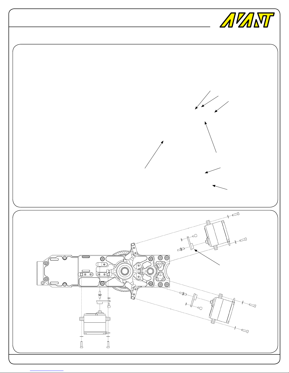
Cyclic Servos Installation
Mostro
700 Nitro
Optional Servo Arm Screw with Pin (3 Total )
M2 Nut (3 Total )
M2 Ball (3 Total )
17mm-17.5mm servo
arm (3 Total )
Note: Servo arm screws
with pins are optional. You
can install the servo arms
with the regular servo arm
screws. The pin adds rigidity
but it’s not mandatory.
M2.5 Washer (12 Total )
M2.5x10 Round Head
Screw (12 total )
17mm-17.5mm servo
arm (3 Total )
Page: 43 Copyright 2014-2015 Avant RC. All rights reserved
Page 44
Avant
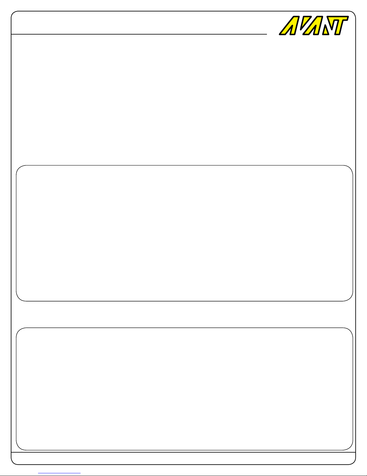
Correct Servo linkage geometry design.
When doing servo linkage geometry you need to take into consideration that the servos are rotating arms and not linear actuators. That
being said it’s an inherent part of a rotating actuator device to have a component of travel that’s undesired and perpendicular to the travel
of interest. This shift is usually called interaction error.
When designing the geometry one needs to take into account that interaction and try to minimize the effects of it during ight so that the
electronics don’t have to work so hard to compensate for mechanical errors. It also help them in the PID engine algorithm calculations so
that the deviations from the expected feedback are minimized and less correction is required.
We understand that from a marketing point of view a perfectly vertical linkage rod at zero degrees collective pitch looks very pretty but we
are too much of perfectionist hardcore engineers to let marketing dictate the correct functioning of the mechanics instead of math.
To illustrate a simplied view of what we’re referring to please take a look at the following pictures.
CORRECT DESIGN:
In the rst picture we can see how the Mostro’s swashplate to servo linkage rod is slightly shifted forward creating a slight angle when
compared to a vertical line. This is done on purpose to minimize the effects of interaction.
Mostro
700 Nitro
As you can see in the next picture at a slight positive or negative pitch the link is vertical. This is where most of the ying happens because when your helicopter is ying it needs either a positive or negative pitch angle to generate lift and prevent it from falling. This is
where you need to try to have the minimum amount of interaction and it’s why at this point it’s vertical.
Page: 44 Copyright 2014-2015 Avant RC. All rights reserved
Page 45
Avant
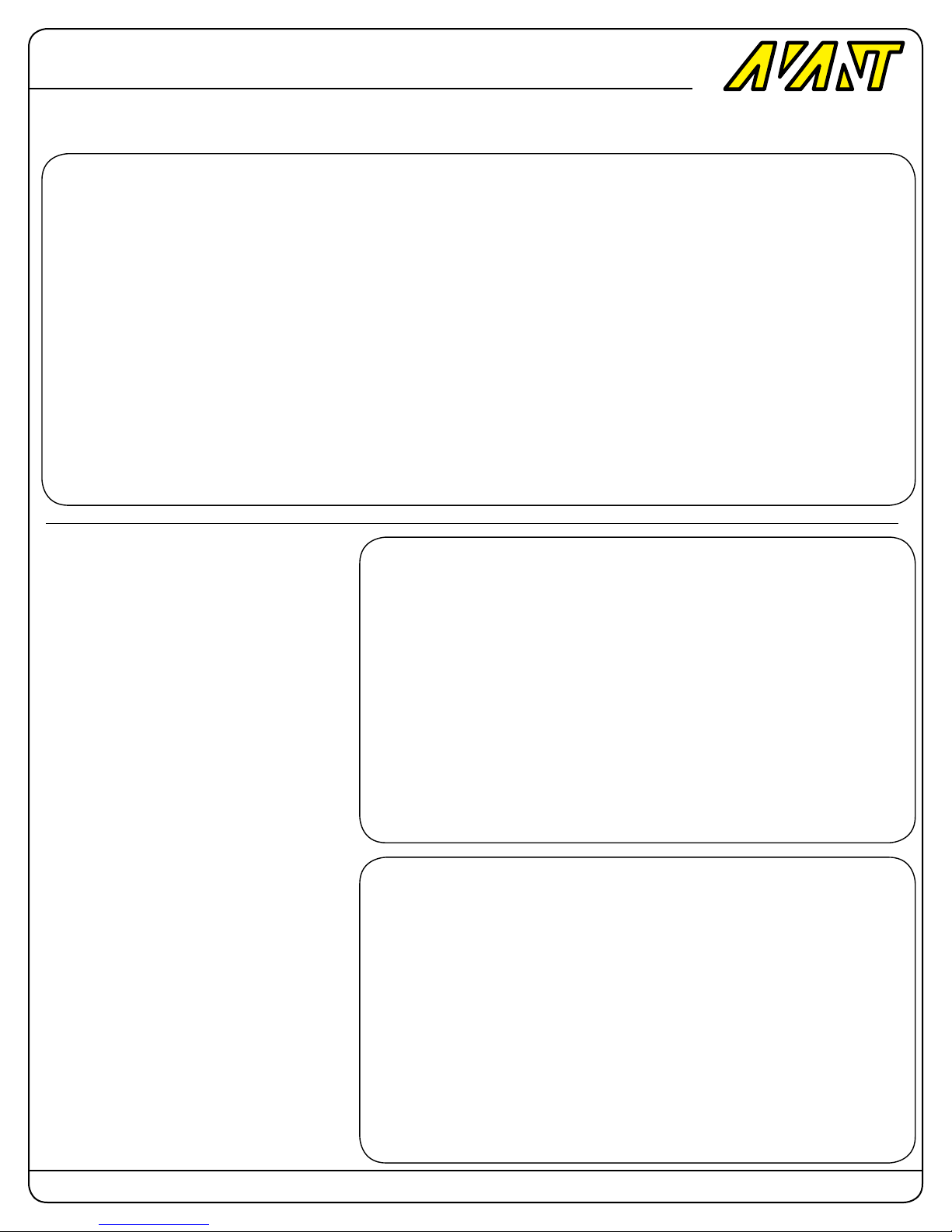
In this picture you can see that at full pitch the interaction angle now goes the opposite way and it’s half of the total angle cutting in half
the potential interaction at full pitch travel.
Mostro
700 Nitro
INCORRECT DESIGN:
Compare this to a poorly designed geometry.
In this case the rods are vertically aligned and
we agree that it looks really pretty because
it seems nice and aligned but that where the
pretty stops because when full pitch is applied
the error from interaction is doubled due to
the unnecessarily excessive angle that the fbl
system needs to ght against.
You can see in this picture how a poorly designed geometry can increase the interaction
error to double what it could be.
.
Page: 45 Copyright 2014-2015 Avant RC. All rights reserved
Page 46
Avant
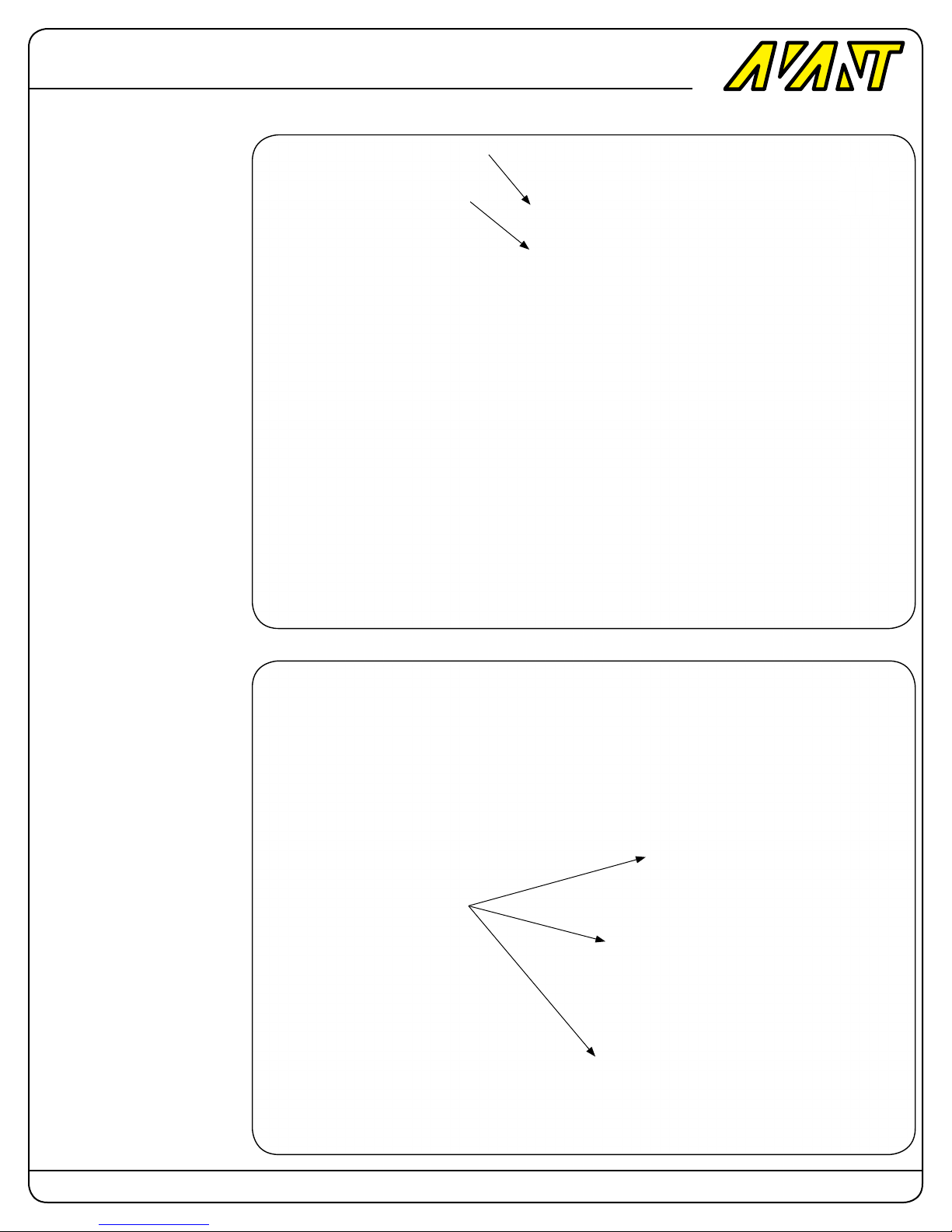
Tail Servo Installation
As shown in this picture install
the tail servo as indicated using
four M2.5x10 Socket Head Cap
screws and Washers.
Mostro
700 Nitro
M2.5x10 Socket Head
Screw (4 total )
M2.5 Washer (4 Total )
Tail Servo Wires Routing
Based on this diagram plan
your tail servo routing accordingly.
Please use heat shrink or
braided sleeves in the areas
where the wires pass near
sharp edges.
Also notice the use of Cable
Ties provided with the kit in the
frame slots.
Use Cable Ties in the slots provided
Page: 46 Copyright 2014-2015 Avant RC. All rights reserved
Page 47
Avant
Throttle Servo Installation
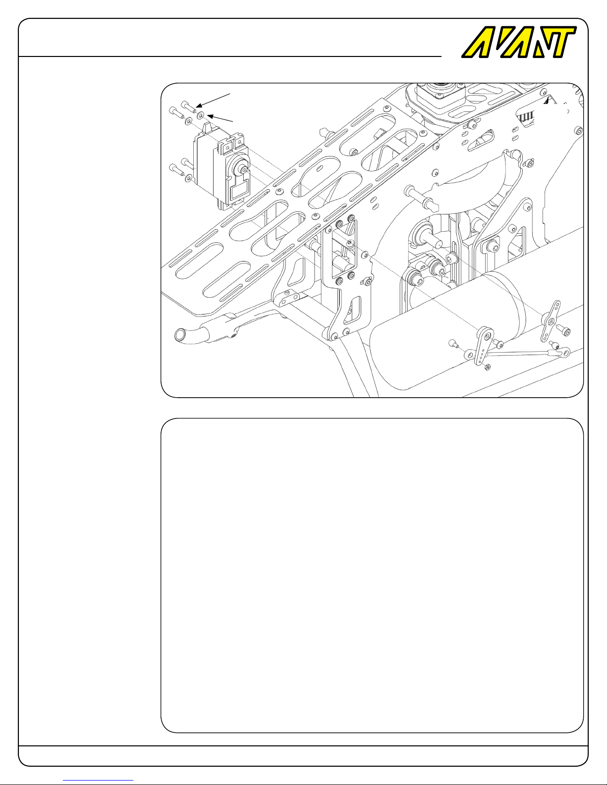
As shown in this picture install
the throttle servo as indicated
using four M2.5x10 Socket
Head Cap screws and Washers.
Use the M2 balls, Ball links and
threaded rod to connect the
servo arm and the throttle arms.
Mostro
700 Nitro
M2.5x10 Socket Head
Screw (4 total )
M2.5 Washer (4 Total )
Throttle Servo Installation
As shown in this picture make
both arms parallel to each
other.
Page: 47 Copyright 2014-2015 Avant RC. All rights reserved
Page 48
Avant
Cyclic Servo Links
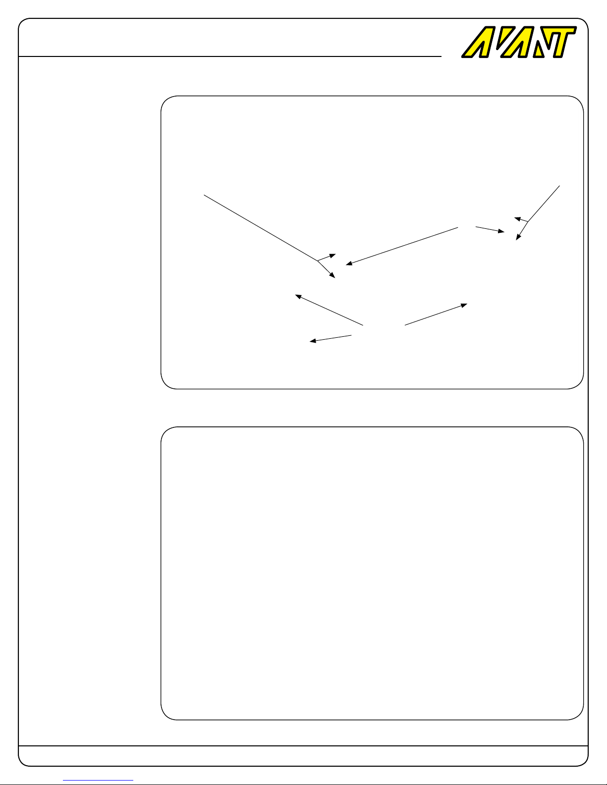
Insert the M2.6x16mm threaded
rod into the links and adjust the
distance to 4mm between the
ball links. Install the three links
into the CCPM servo arms as
indicated in the picture.
Mostro
700 Nitro
4mm spacing
between ball
links
4mm spacing
between ball
links
M2.5x16
Threaded
Rod
17mm-17.5mm servo
arm (3 Total )
Tail Pushrod Front Link
Install the front ball link into the
tail servo ball.
Page: 48 Copyright 2014-2015 Avant RC. All rights reserved
Page 49
Avant
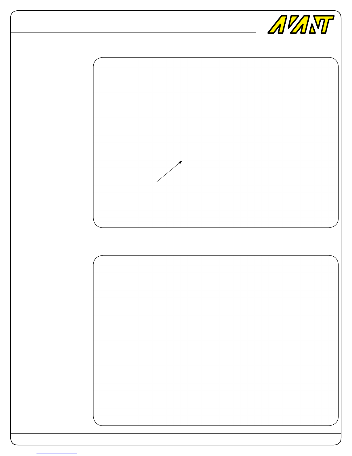
Tail Pushrod Back Link
Install the back ball link into the
L-Lever ball.
Mostro
700 Nitro
Install Heat Shrink Tube
on the tail pushrod.
Tail Pushrod Back Link
Install the back thick ball link
into the L-Lever ball.
Page: 49 Copyright 2014-2015 Avant RC. All rights reserved
Page 50
Avant
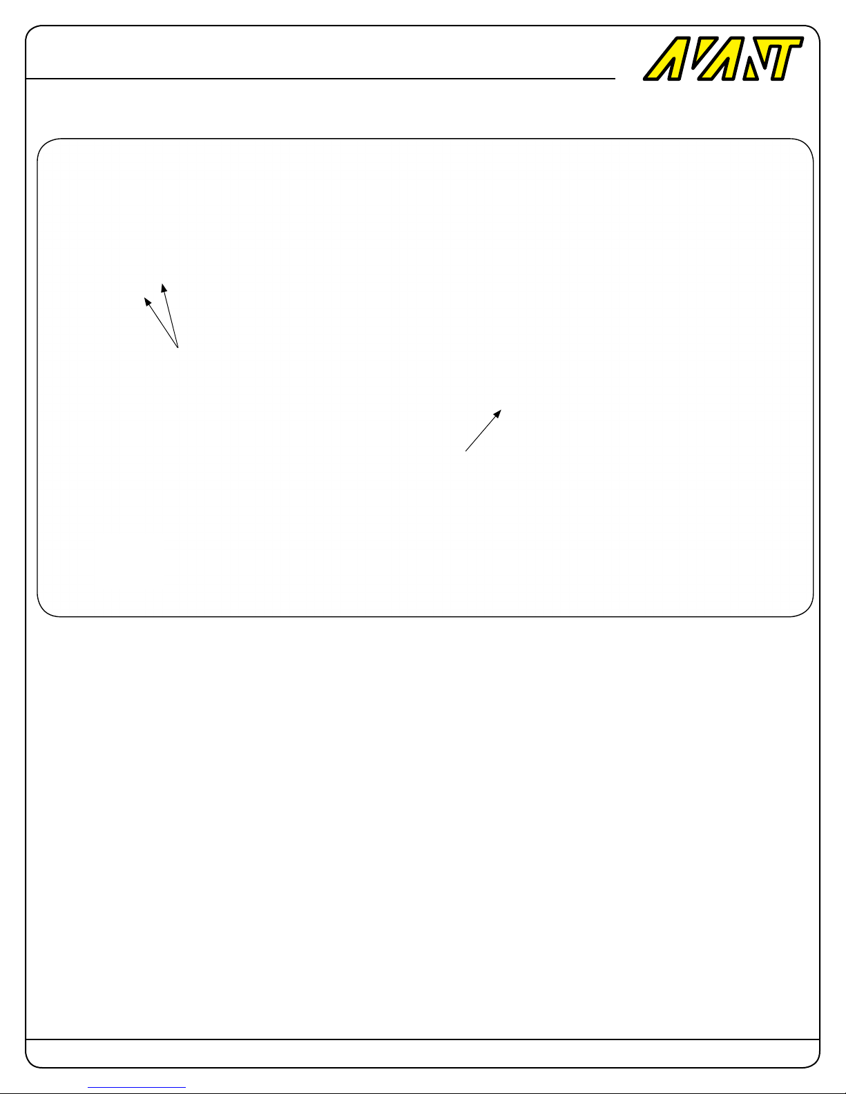
Canopy Preparation
Mostro
Install Supplied Velcro loop (Soft
side) Securing strips as indicated.
700 Nitro
Install Supplied Canopy Grommets
as indicated (4 total)
Rub some grease onto the inside of the canopy grommets
to make it easier for the Thumbscrew and the front canopy
posts to go into the grommets.
Page: 50 Copyright 2014-2015 Avant RC. All rights reserved
Page 51
Avant
Canopy Preparation
Wrap the provided Velcro
Hook Strip (Hard Side)
around the boom as indicated
at a distance of approximately
105mm from the boom clamp
Mostro
700 Nitro
Thumbscrew
Thumbscrew
Complete the installation of
the ESC, FBL unit and any
electronic or battery you plan
on using.
Page: 51 Copyright 2014-2015 Avant RC. All rights reserved
Page 52
Avant
You can now proceed with
Programming and setup of
your electronics,
Mostro
700 Nitro
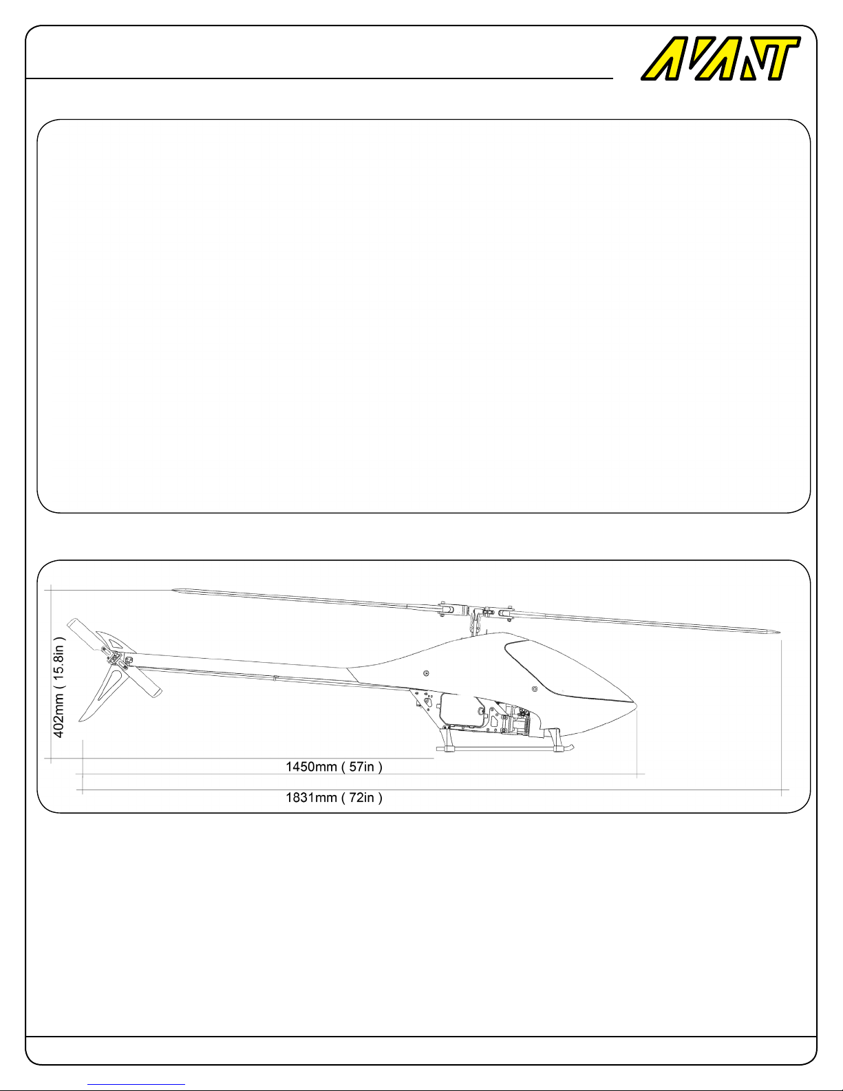
Dimensions with 710mm blades
Page: 52 Copyright 2014-2015 Avant RC. All rights reserved
 Loading...