


English
Operator's Manual
2017-
A423110 2017 1 EN 2017-
www.avanttecno.com
https://tractormanualz.com

Avant e5 2017 1
2
TABLE OF CONTENTS
INTRODUCTION ....................................................... 3
Foreword ................................................................................... 3
Make sure all relevant manuals are available ..................... 4
Intended use .............................................................................. 5
Avant warranty ......................................................................... 7
SAFETY FIRST ............................................................ 8
General safety instructions .................................................... 8
Operation on uneven surfaces, gradients, and near
excavations ................................................................................ 11
Personal safety and protective equipment......................... 12
Electric system and handling of the battery pack ............. 14
DESCRIPTION OF THE LOADER ............................ 17
Identification of the loader .................................................... 17
Main parts of the loader ......................................................... 18
Signs and decals ........................................................................ 19
Technical specifications .......................................................... 22
General specifications ............................................................. 23
Auxiliary hydraulics oil flow .................................................. 24
Tyres............................................................................................ 25
Wheel spacers .......................................................................... 25
Tipping load ............................................................................... 27
Tipping load - load chart ........................................................ 28
Rated operating capacity ........................................................ 29
CONTROLS AND OPTIONS OF THE LOADER .... 30
Dashboard .................................................................................. 31
Control of loader boom, auxiliary hydraulics and
other functions ......................................................................... 32
Parking brake switch ............................................................... 35
Multi-function display .............................................................. 35
Electric 12 V outlet .................................................................. 35
Seat - Seat belt and seat adjustments .................................. 36
Seat heater ................................................................................. 36
Lights ........................................................................................... 37
CAB L (optional extra) ........................................................... 38
Options ....................................................................................... 39
OPERATING INSTRUCTIONS ................................. 43
Starting the loader ................................................................... 44
Ignition key ................................................................................. 44
Battery disconnect switch ...................................................... 45
Stopping the loader (Safe stopping procedure) ................ 45
Drive control ............................................................................. 46
Material handling ....................................................................... 50
In case the machine tips over ................................................ 52
Transport instructions and tie down points ..................... 53
Lifting ........................................................................................... 54
Storage ........................................................................................ 55
WORKING WITH ATTACHMENTS ........................ 56
Requirements for attachments ............................................. 56
Coupling the attachments ...................................................... 57
Coupling the hydraulic hoses of the attachment ............. 60
Using the auxiliary hydraulics ................................................ 61
Releasing the residual pressure of hydraulic system ....... 62
BATTERY AND CHARGING ..................................... 63
Charging the battery ................................................................ 65
Charger plug type ..................................................................... 66
Battery maintenance - water refill ....................................... 68
Watering procedure ................................................................ 69
SERVICE AND MAINTENANCE ............................... 70
Access to electric motor compartment ............................. 71
Installing of service support and frame lock ...................... 72
Daily inspections ....................................................................... 73
Maintenance schedule ............................................................. 75
Loader maintenance ................................................................ 76
Battery maintenance ................................................................ 82
Electric system & fuses ........................................................... 85
TROUBLESHOOT ...................................................... 87
SERVICES MADE ........................................................ 89
INDEX .......................................................................... 94
Original instructions
https://tractormanualz.com

Avant e5
3
Introduction
Foreword
AVANT TECNO OY wants to thank you for purchasing this fully electrically powered AVANT loader. It represents a
new level of quiet operation with no local emissions and low operating costs. The battery powered model line is
designed and built upon Avant’s long experience with compact loaders and is manufactured in Finland. We ask
you that you read and understand the contents of this manual completely before operating the loader. This
operator’s manual is intended to help you to:
operate this machine safely and efficiently
observe and prevent situations that may cause a risk or danger
keep the machine in good condition and its life span as long as possible
The following warning symbols are used throughout this manual to indicate factors that must be considered to
reduce the risk of personal injury or damage to property:
WARNING:
This safety symbol refers to important safety information in this manual.
It warns of an immediate hazard that could cause serious personal
injury.
Read the warning text accompanying the symbol carefully and ensure
that other operators are also familiar with the warnings, since personal
safety is at stake.
DANGER:
This signal word indicates a hazardous situation which, if not avoided, will cause death or
serious injury.
WARNING:
This signal word indicates a potentially hazardous situation which, if not avoided, could
cause serious injury or death.
CAUTION
This signal word is used when minor injury could result if the instructions are not followed
properly.
This signal word indicates information about the correct operation and maintenance
of the equipment.
Failure to observe the instructions accompanying the symbol can lead to equipment
breakdown or other property damage.
https://tractormanualz.com

Avant e5
4
.
Make sure all relevant manuals are available
DANGER
Wrong use of the equipment can cause death or severe injuries - Make sure to read
all relevant manuals and instructions thoroughly and keep them available for all
operators.
Using each attachment requires specific information about correct use, mounting
procedure, safety, and how to avoid hazardous situations. An attachment may introduce
risks that are not present when operating the loader with other kinds of attachments.
Always read the operator's manual of each attachment carefully.
Manuals of attachments
DANGER
Attachments can create significant risks that are not
covered by this Operator's manual of the loader.
Make sure you have all attachments manual available.
Wrong use of an attachment can cause serious injuries or
death.
Each attachment is accompanied by its own respective
Operator’s Manual. The manual will show important
information related to safety, and how to attach, use, and
maintain each attachment correctly.
Spare parts list
All spare parts of the loader are listed in a separate spare
parts list.
Contact your Avant service partner or dealer to order
parts. Have the serial number of the loader available when
ordering to ensure correct parts.
https://tractormanualz.com

Avant e5
5
.
Intended use
The Avant eSeries loaders are battery powered, hydraulically operated, articulated compact loaders. They are
designed and manufactured for both private and professional use. The loader can be equipped with a range of
attachments offered by Avant Tecno Oy, which enables you to do several different jobs with the same machine.
Because of this multi-purpose nature of the machine and the various attachments and tasks, read always not only
this Manual but also the Operator's Manual of the attachment, and follow all instructions. Every person who deals
with this machine must follow work safety regulations, all other generally accepted rules related to work health and
safety, and all road traffic regulations.
Remember that safety consists of several factors. The loader, by itself or equipped with an attachment, is very
powerful and can cause serious personal injuries or property damages if it is operated in a wrong or careless way.
Never allow the compact size of the loader to distract from this fact and keep it in mind when you consider to allow
another user to operate it. Do not operate an attachment unless you have familiarised yourself with the use of it
and the eventual dangers and risks related to it. Take the keys with you when you leave the loader unattended to
prevent other, unfamiliar persons to operate the machine. The loader is not intended to lift or transport people or
be used as a work platform. Different jobs require different attachments, and it is not allowed to handle any
material or loads without any attachment fitted.
This loader has been designed to need as little maintenance as possible. The operator can perform the routine
maintenance operations. There are however more demanding service operations that can be done by professional
service personnel only. Wear appropriate protective equipment when you do any service or maintenance work.
Original spare parts must be used. Familiarise yourself with the service and maintenance instructions in this
Manual. Operating a loader that is in poor condition, or that has received unauthorised modifications, can be
hazardous to the operator and bystanders.
Contact your local AVANT dealer, if you are uncertain of anything concerning the operation and maintenance of
this loader, or for any questions, service, or spare parts.
In addition to the safety instructions included in this manual, you must observe all occupational safety regulations,
local laws, and other regulations concerning the use of the equipment. Particularly the regulations concerning the
use of the equipment on public road areas must be observed. Contact your Avant dealer for more information
about local requirements before you operate the loader on road areas.
This loader has been designed to require as little maintenance as possible. The operator can perform the routine
maintenance tasks. There are however more demanding service operations that must be done by professional
service personnel only. It is allowed to perform service operations only when wearing appropriate protective
equipment. Original spare parts must be used. Familiarise yourself with the service and maintenance instructions
in this Manual. Operating a loader that is in poor condition, or that has received unauthorised modifications, can be
hazardous to the operator and bystanders.
Battery operated e5
Ambient temperature will limit the energy that is available from the batteries. Battery performance may decrease
significantly at temperatures below 0ºC (32ºF) and batteries can be discharged more quickly. Charging of the
loader is not recommended at temperatures below 0ºC (32ºF). Discharged batteries may freeze in cold
environment and frozen batteries must never be charged. See instructions in this manual regarding operating
environment, charging, and safety of battery systems
The loader is designed to operate with the battery pack supplied with the loader and approved by the
manufacturer. The battery pack must be charged only with the charger provided with the loader, or other charging
system supplied by Avant for this loader model. Using any other batteries or chargers can cause fire or explosion
of batteries and risk of electric shock.
Maintenance tasks that you can do to this system without special training and qualification are limited to charging,
water fill, cleaning, replacement of fuse. Never connect any device directly to the battery.
https://tractormanualz.com

Avant e5
6
.
Operator qualification
Only operators who have studied this manual, and all relevant attachment manuals, are allowed to use this loader.
Regardless of your possible previous experience with lawn-mowers, loaders, ATVs, or other equipment, it is
important that you learn the driving principle of this loader. Practise how to operate the loader and its attachments
safely at an open area before you use the loader near other persons.
You must be in good physical and mental condition with the ability to stay alert and to observe the surrounding
area. Never use the equipment while under influence of medication which could impair your abilities to operate the
equipment safely. Do not operate the loader if you are under the influence of alcohol or any other intoxicant during
the work shift.
Depending on operating area, you may also be required to read, understand and comply with all applicable
Employer, Industry and Governmental rules, standards and regulations.
Electric qualification
You can replace the battery pack with a similar one supplied by the manufacturer. Other battery or electric related
maintenance that is not shown in this manual, is prohibited. Leave all electric parts from the battery connector
forward to authorised service professionals to avoid risk of electric shock, fire, and short-circuiting and explosion of
battery. High-voltage cables and connectors, inverter, and electric motors do not have components that can be
maintained by user.
Versions of this manual
Avant has a policy on continuous product development. Updated versions of the manual replace the previous
versions of this manual as long as the year on the cover page matches with the original manual. You can ask for
the latest manual from your dealer. Some of the features or technical details presented in this manual may change
without notice. The pictures in this manual may show optional equipment or features that are not currently
available in your market area. We reserve the right to change the contents of the manual without notification.
Keep this manual with the loader
Read this manual before use. Put this manual, as
well as manuals of attachments, into the storage
box behind driver's seat when you have read
those. Always keep this Operator's Manual with the
loader. If this Manual gets lost, ask for a new copy
from your Avant dealer. Also remember to give this
Manual to the new owner when the machine
changes ownership.
https://tractormanualz.com

Avant e5
7
.
Avant warranty
This warranty specifically applies to the Avant e5 loader only and not to any attachments used with this product.
The battery is covered by special warranty clauses listed below. Any repairs or modifications performed without the
prior authorisation of Avant Tecno Oy will cancel this warranty. During the first two years of operation or first 1000
hours (whichever is the soonest) Avant Tecno Oy warrants to replace any part or repair any defect which may
occur, subject to the terms detailed below:
1. The product has received regular maintenance in accordance with schedules given by the manufacturer.
2. Any damage caused by operation in a negligent manner or exceeding the approved specifications detailed in
this manual is excluded.
3. Avant Tecno Oy accepts no responsibility for interruption to working or any other consequential losses
resulting from any failure of the product.
4. Only Avant Tecno Oy approved replacement or original quality parts shall be used during routine
maintenance.
5. Any damage caused by the use of incorrect fuel, lubricants, cooling liquid, or cleaning solvents is excluded.
6. The Avant Warranty excludes any consumable parts (e.g. tyres, batteries, filters, belts etc.) except where it
can be clearly shown that these parts were defective on original supply.
7. Any damage caused resulting from the use of attachments not approved for use with this product is
excluded.
8. The battery must be used, recharged, and maintained as instructed in this manual. Damages caused by
neglected maintenance or repeated deep discharge cycles are not covered by the warranty. See warranty
period for battery below.
9. In the event a fault occurs which is attributable to manufacturing or assembly defect you should arrange to
return your AVANT to your authorised dealer for repair. Travel and freight costs are excluded.
Special warranty terms regarding the battery
During the first year of use, battery is under full warranty covering parts regarding the battery. After the first year
and until the end of second year (months 13 to 24) the battery is under partial warranty. During this 13 to 24 month
term warranty coverage is calculated by the age of the battery, and the cover declines by the operation age of the
battery. The responsibility of the customer regarding parts and material costs of the battery starts from month 13 of
the warranty period at 13/24 parts of the full cost of replaced parts, ending at full 24/24 at the end of the warranty
period.
.
..
https://tractormanualz.com

Avant e5
8
Safety First
DANGER
Incorrect or careless operation of the loader may cause a serious accident. Before you
operate the machine, familiarise yourself with the use of the machine and read and
understand this Operator's Manual, as well as all relevant safety instructions, local
regulations, and safe working practices.
Understand the limitations of speed, braking, steering and stability as well as loading
capacity of the machine before starting operation. Make sure that everyone who operates
or works with this equipment is familiar with these safety precautions.
If you have no previous experience of the machine, make sure to do all testing at a safe
and open place with no persons in the area of operation.
General safety instructions
1. Remember the correct working position. When
driving, be comfortably seated in the driver´s
seat, keep your feet in their proper place in the
footwell and at least one hand on the steering
wheel.
2. When seated, always keep the seat belt
fastened and keep hands and feet inside the
operator’s area.
3. Before leaving driver’s seat, always:
Lower the loader boom and place attachment
flat on ground
Relieve residual hydraulic pressure (see
page 62)
Engage the parking brake
Switch off the electric motors, remove the
ignition key
4. Start the operation slowly and carefully.
Practise driving of the machine at a safe and
open place before connecting any attachment,
and follow the instructions in this Manual and
also the operator's manual of the attachment.
5. Operate the control levers with careful and
deliberate movements. Avoid abrupt
movements when handling the load, in order to
prevent the load from falling and to keep the
machine stable.
6. Keep away from the danger zone of the lifted
boom and don’t let anyone go there.
7. Keep your hands, feet and clothing away from
all moving parts, hydraulic components, and
hot surfaces.
8. Make sure that there is enough open space
around the machine for safe driving.
9. Do not transport the load with the boom lifted.
Always carry bucket or attachment as low as
possible, and put the load down whenever you
leave the machine.
10. It is not allowed to transport persons with this
machine. Do not transport or lift persons in the
bucket or in any other attachment. Lifting of
persons is only allowed with the attachment
designed for this purpose: the Avant Leguan
50 access platform, following the instructions in
the Operator's Manual of Leguan 50
attachment.
11. Do not exceed the tipping load. Familiarise
yourself with and follow the load diagrams in
this Manual.
12. When turning with the machine, remember that
the driver´s seat extends beyond the turning
radius of the wheels (collision risk).
13. Do not operate the loader in an explosive
environment or in a place where dust or/and
gases can create a fire or explosion hazard.
14. Keep the areas around the battery, inverter,
electric motors, and cooling fan clean of
flammable materials.
15. Read the lifting, towing and transportation
instructions on page 54.
16. Remove the ignition key from the ignition
whenever leaving the machine unattended.
https://tractormanualz.com
Avant e5
9
17. Follow all inspection, service and maintenance
instructions. If you notice any faults or
damages on the machine, these must be
repaired before starting operation.
18. Before any maintenance or repair operation
always stop and switch off the loader, lower
the boom down and release pressure from
hydraulic system. Read safety instructions for
maintenance on page 70.
19. Do not let any person operate this loader who
has not read safety instructions and is not
familiar with the safe and correct use of this
loader.
20. Never operate the loader or attachments while
under the influence of alcohol, drugs,
medication that may impair judgement or
cause drowsiness, or if not otherwise medically
fit to operate the equipment.
.
..
Safety devices are installed for your safety Never modify or bypass any safety function
DANGER
Safety functions are installed for
your safety. Never modify or block
any of the safety systems of the
loader. If you notice that a system
is not in good condition, stop the
use of the loader and make sure
the is serviced.
.
..
Sudden movements can tip the machine over Risk of overturning
WARNING
Movements, such as stopping,
turning, or lowering the boom
abruptly, can cause loss of
stability. Always drive slowly and
operate the controls of the loader
very carefully, especially when
handling heavy loads.
.
..
Articulated frame - Risk of overturning
WARNING
Turning articulated frame can lead
to overturning of the loader on
inclined terrain or when driving at
high speed. Never turn frame
towards the slope while operating
on inclined ground.
Always drive slowly when carrying
load or when turning with the
machine.
.
..
Overload - Risk of overturning
CAUTION
The high lift capacity of the loader
makes it possible to exceed the
stability of the loader when
handling loads. Read the
instructions regarding maximum lift
capacity and load handling in this
Operator's Manual. Following the
instructions reduces the risk of
tipping the machine over its front
axle, but the operator must be
aware of the limits of the machine
and follow safe working practises
to avoid overturning of the
machine.
.
..
https://tractormanualz.com

Avant e5
10
WARNING
Never take a heavy load on the
loader from high level – e.g. from
truck, shelf etc. – risk of tipping
over!
If the load is too heavy when lifting
load from a high level, the loader
could tip forward when reversing
with the loader.
Never reverse and drag with the
loader before you make sure that
the loader can handle the load that
is being lifted.
When loading, always keep the
loader frame as straight as
possible.
.
..
Falling of load or unexpected lowering of loader
boom - Risk of crushing
WARNING
Always remember that the boom
may lower unexpectedly due to
loss of stability, mechanical fault,
or if another person operates the
controls of the loader, leading to
crushing hazard. The attachment
or the loader are not intended to be
left to keep a load elevated for
longer periods. Lower the
attachment before leaving the
driver's seat. The stability of the
loader may change when leaving
the driver’s seat, leading to tipping
over of the machine.
.
..
Risk of falling objects
WARNING
Make sure load is securely on the
attachment. Never tilt the
attachment back when it is lifted
high. Operate only with machines
equipped with ROPS and FOPS
structures.
.
..
Falling of persons - Risk of crushing
WARNING
Never use the loader or its
attachments to lift persons or as
any kind of work platform even
temporarily. Never climb on the
loader or on the attachment.
Seating capacity: one person only.
.
..
Moving loader can crush - Engage parking brake
before working near the loader
WARNING
Follow safe stopping procedure to
prevent all movements of the
loader. Avoid leaving the loader
parked on hill. If necessary to park
on hill, use chocks or other
additional means to prevent the
loader from moving.
.
..
https://tractormanualz.com

Avant e5
11
Pinching points - Avoid pinching between loader
frame itself and between loader and walls - Keep
all body parts within the safety frame
CAUTION
Movements of the articulated
frame creates pinching hazards.
Keep your head, hands, and feet
inside the loader. Be especially
careful while you drive near walls
and trees. Keep your hands on
steering wheel and joystick.
.
..
Avoid pinching hazard for legs - Do not turn the
steering wheel while standing near the loader
CAUTION
Turning the articulated frame
creates a pinching hazard to a
person standing near the tyres of
the loader. Never grab the steering
wheel while entering or leaving the
driver's seat to avoid turning of the
frame. Stop the loader if other
persons get close to the machine.
Check that tyres that are larger
than standard tyres leave enough
space between the tyres for safe
use.
Operation on uneven surfaces,
gradients, and near excavations
Extra caution is needed when using the equipment
on inclined terrains and slopes. Drive slowly
especially on inclined, uneven, or slippery surfaces,
and avoid sudden changes in speed or direction.
Operate the controls of the loader with careful and
smooth movements. Watch out for ditches, holes on
the ground, and other obstacles, as hitting an
obstacle may cause the loader to tip over.
Overturning of machine can lead to death or
serious injury
WARNING
The stability and the load handling
capacity of the loader are
significantly reduced on inclined
terrains and maximum lifting
capacity can be achieved only on
firm, level ground. On horizontally
tilted terrain the load must be kept
close to the ground and must
never be lifted high.
.
..
Handle heavy loads only on even surfaces.
Drive very slowly on uneven terrains. Load,
unload, and turn the machine on flat level ground
only. Lifting a load or turning on uneven surfaces
can lead to loss of stability.
Do not drive on too steep a gradient - watch out
for ditches, manholes and steep gradients, which
may cause the loader to tip over.
Never drive along an excavation. Note that the
excavation or trench may suddenly cave in.
Exercise extreme caution when driving near
ditches or embankments, and avoid driving along
a ditch or trench, as the machine could suddenly
tip over if an edge caves in. Avoid driving along
trenches and keep at least a distance equal to
width of a trench.
Do not park the machine on a surface with a
gradient. Should this be necessary, engage the
parking brake and preferably turn the machine
sideways and put down the load. If needed, use
chocks behind the wheels.
https://tractormanualz.com

Avant e5
12
Personal safety and protective
equipment
Wear safe clothing and personal protective
equipment.
Protect yourself against work hazards like noise,
ejecting debris or dust for example.
Follow regulations regarding protective
equipment. Wear eye protection and hard hat or
other protective equipment as needed.
Read Operator's Manual of the attachment for
more information about protective equipment
needed in the work.
The noise level at the driver's
seat may exceed 85 dB(A).
Wear hearing protection while
working with the loader.
Wear protective gloves.
Wear safety boots whenever
working with the loader.
Wear safety glasses when
handling hydraulic components.
Always fasten seat belt while
operating the machine.
When working at construction
sites, a safety helmet is
recommended and may be
mandatory in addition to the
falling objects protective
structure (FOPS) on the loader.
Depending on work and working
area, also a respirator mask may
be required. Find out about other
necessary safety equipment at
your specific work site.
CAUTION
Silica dust warning. Prolonged
exposure to crystalline silica can
cause a lung disease called
silicosis. Occupational health and
safety officials recommend limiting
exposure to dust that is present at
most earth-moving and many other
work sites. Avoid spreading of dust
where possible, keep loader cabin
clean from dust, use respiration
mask when necessary.
Safety frame (ROPS) and safety
canopy (FOPS)
The loader is equipped with a Rolling Over Protective
Structure (ROPS) and a Falling Object Protective
structure (FOPS). These safety structures are
important parts of operator safety, and they must be
fitted on the machine.
Safety frame (ROPS) protects the operator in case
the machine tips over. Fasten seat belt while
operating a machine with a ROPS. All cab versions
are ROPS & FOPS tested and certified.
Crushing hazard - Always keep safety structures
installed
WARNING
Never take off the safety
structures, modify them, or attempt
to repair. If damaged, contact
service.
Always fasten the seat belt in order
to stay inside the protected area of
the safety frame.
Modifications
Any modification to this machine must be approved
beforehand by an authorised Avant representative. If
you modify the loader or attachment, it can become
dangerous and cause serious injuries or even death.
Unauthorised modifications can increase the risk of
accidents and damage or shorten the service life of
the machine. Modifications to electric systems can
make the no longer compliant with regulations
concerning electromagnetic emissions. Use only
original spare parts to make sure that the product is
kept in safe operating condition.
https://tractormanualz.com

Avant e5
13
Working near powerlines
Digging may expose buried electric cables, and
some attachments may make it possible to reach
overhead powerlines with the loader, creating hazard
of electric shock and electrocution.
Plan work ahead and take necessary safety
precautions.
Stay away from electric cables - Electrocution
hazard
DANGER
Electric shock hazard - Contact
with or working too close to electric
wires can result in lethal electric
shock. Keep the loader and any
attachment at a sufficient distance
from all electric cables, see table
below.
Table 1 - Safety distance from powerlines
Voltage level
Safety distance
0 - 1000 V
2 m
1 - 45 kV
3 m
110 kV
4 m
220 kV -
5 m
Unknown voltage
5 m
If electric cables are exposed during digging, or in
case of inadvertent contact or proximity with live
electric source:
Do not leave the loader until the electricity has
been disconnected by qualified technicians,
usually local electric company.
If absolutely necessary, jump out from the
loader, keeping feet next to each other, until at a
safe distance.
Warn others not to approach the loader until safe
to do so.
Fire prevention
Clean the loader to avoid build-up of flammable
debris, such as dust, leaves, hay, straw, etc.
There are many parts on the electric system that
operate at high temperatures in normal use. To
avoid fire, and to ensure that the cooling of
electric systems is ensured, keep the electric
parts clean. Overheating of electric parts can
shorten their service life.
Static electricity can produce sparks when
removing plastic covers.
Do not smoke while you work near the battery, or
do any maintenance work of the hydraulic
system.
Add hydraulic oil only at a well ventilated place.
Oil leaks can ignite on hot components. Repair
any damaged or leaking components before
using machine.
Know where fire extinguishing equipment is located
near your working site. At some areas a fire
extinguisher may be mandatory. Keep a
multi-purpose, approved type fire extinguisher
available near the place where you store the loader.
https://tractormanualz.com

Avant e5
14
.
Electric system and handling of the battery pack
WARNING
The loader is fitted with a high-energy battery pack that can output hazardous, lethal
levels of current and voltage. Misuse or using of damaged battery system creates a
risk of battery explosion, fire, hazardous electric shock, and acid spill from battery.
Follow the instructions regarding charge, use, and maintenance of the battery and the
electric systems in this manual.
Battery systems on e5
The energy from the battery pack is used in two
parallel systems:
48-volt supply from battery is converted by an
inverter to a high-voltage and high-current
electric power to drive the electric motors
A 48 v to 12 v converter supplies electricity to the
control systems of the loader, hydraulic valves,
dashboard, electric socket etc.
Never modify the 48-volt system or connect any
device directly to it. This system can output high
current that can kill or cause electric shock and
burns, if handled carelessly and safety systems are
bypassed. See maintenance instructions on page
75.
DANGER
Short-circuit can cause the
battery to explode or burn Disconnect battery before
maintenance.
Isolate the battery from the electric
systems of the loader by
separating its quick connector
before working on the electric
systems of the loader, see page
82. Check that all insulator sleeves
and caps are in good condition and
that battery terminals are not
exposed. Never lay metal objects
on the battery.
Handle battery with care
Battery contains corrosive sulphuric acid which
causes serious burns upon skin contact. Avoid
contact with skin or clothes. If electrolyte gets on
your skin or clothes, flush with a lot of water. In
case of contact with eyes, flush with a lot of
water for at least 15 minutes and see a doctor
immediately.
If a fuse is blown repeatedly, find out the cause.
Always use fuses with correct rating.
Disconnect the battery by separating the main
connector. Never disconnect individual battery
cells.
CAUTION
Risk of exposure to battery acid
- Handle battery with care and
read maintenance instructions.
Using a damaged battery, extreme
heat, improper charging procedure,
or other type of wrong use can
cause the battery cells to rupture
and leak or spray acid electrolyte.
Always follow use and
maintenance instructions. Never
use damaged battery.
CAUTION
Lead warning - Wear protective
gloves. Battery and its terminals
contain lead, a harmful substance
which should not be handled more
than what is necessary. Wear
protective gloves when handling
battery. Wash hands with soap and
water after handling the battery.
https://tractormanualz.com

Avant e5
15
WARNING
Risk of electric shock and
contact with acid - Never
disassemble the battery pack.
Battery pack does not include
other serviceable parts than those
described on page 75. Never
remove individual battery cells
from the battery pack. Keep all
insulators in place.
First aid measures
WARNING
Risk of serious burns - Avoid
contact with battery acid.
Battery contains sulphuric acid
as electrolyte. This acid is highly
corrosive and can cause serious
skin burns, in case of contact
with skin. If acid gets to eyes,
there is a serious risk of severe
eye injury. Follow correct
handling instructions of battery to
avoid exposure to acid. Always
use only battery that is in good
condition.
In case you are exposed to battery electrolyte
(sulphuric acid):
After contact to skin:
Rinse immediately with plenty of water. Remove
and wash wetted clothing.
After contact with eyes:
Rinse immediately with plenty of running water
for several minutes and seek medical advice
immediately.
If you inhale acid mist:
Inhale fresh air and seek medical advice:
After swallowing:
Drink a lot of water immediately. Swallow
activated carbon and seek medical advice
immediately.
Follow correct charging procedure
Ensure ventilation and remove the rear cover
before recharge
Recharge the loader only at a well-ventilated place.
Never recharge in a small garage or shed, where
there is no fan-operated ventilation to ventilate gases
to outdoor air.
To allow the battery gas to ventilate properly, remove
the rear top cover and leave open when recharging
the battery. Leaving the rear cover removed will also
allow the battery to cool better during recharge.
Use only the integrated charger of the loader to
charge the battery
Use only the original, integrated charger to charge
the battery. This ensures that the charge voltage and
current are optimised in different phases of the
charge cycle. Other charger types, especially those
with higher output current, can overheat the battery.
Overheating can cause the electrolyte to boil and
battery can deteriorate or its useful life will be
shortened as a result.
During charge, some of the water in the battery is
broken into hydrogen and oxygen gases. This gas
mixture is highly flammable and can become
explosive, if enough gas is accumulated. The area
where the loader is charged must be ventilated so
that the amount of these released gases will not
become explosive.
Make sure that the ventilation is sufficient when
charging the battery. Preferably charge the
loader outdoors.
Keep arcs, sparks, flames, lighted tobacco and
other sources of heat away from battery.
Charge the battery only with the built-in charger
of the loader. If you connect any other charger to
the battery, the battery can get too hot, too high
current can cause electrolyte to spill from the
battery, and the battery can be damaged.
Check the battery for external damages,
leakages, and deformations. Never charge the
battery or operate the loader if you see that the
battery is damaged.
https://tractormanualz.com

Avant e5
16
WARNING
Battery produces explosive
gas during recharge - Make
sure to charge only on well
ventilated area.
Make sure that
ventilation is sufficient
when charging the
battery.
Never charge the
loader in a small
garage or shed where
there is no ventilation.
Keep arcs, sparks,
flames, and lighted
tobacco away from
battery.
Never charge damaged
or frozen battery.
See detailed
instructions about
charge process starting
from page 63.
WARNING
Risk of battery explosion - Never
charge frozen battery.
Discharged battery can freeze. A
frozen battery can explode during
charging. Never charge a frozen
battery, allow the loader to warm at
a warm place first, if loader has
been left in freezing temperatures
with low battery. Prevent freezing
by keeping the battery charged
especially when there are chances
of freezing temperatures.
To ensure fire safety during recharge
Follow correct recharge instructions. Battery
produces explosive gases during recharge and
therefore ventilation must be ensured. Sparks,
lighted tobacco products, and other sources of
ignition must be kept away from loader during
recharge.
Plug the loader only to a grounded mains plug.
It is recommended to use a mains outlet with a
residual current switch device to protect from
electric shock in case insulation of cables is
damaged. Those devices must be tested
periodically.
Use extension cables only if necessary. Use as
short cables as possible. Choose only high
quality cables with large conductor cross-section.
Poor quality cables can heat up and even burn.
Avoid cable loops to prevent heating of the
cable. Unwind any long cable that is coiled,
otherwise the cable can overheat and burn.
During charge, the electric power that runs
through the cable is about 2300 watts.
Make sure the fuses of the mains plug are
adequate for the loader.
Avoid creating static electricity while loader is
charging. Do not wipe or otherwise clean the
loader during charge.
Make sure all charger and battery cables are
insulated and correctly connected.
https://tractormanualz.com

Avant e5
17
Description of the loader
.
..
Identification of the loader
Write down the identification information of your loader in the following fields, it facilitates ordering of spare parts
etc.
1.
Loader model
2.
Loader serial no.
Serial number of the loader is printed on the type plate, which also indicates the loader model.
Dealer:
Contact information
Loader identification
Loader identification plate is located on the right
side of the steering wheel.
https://tractormanualz.com

Avant e5
18
.
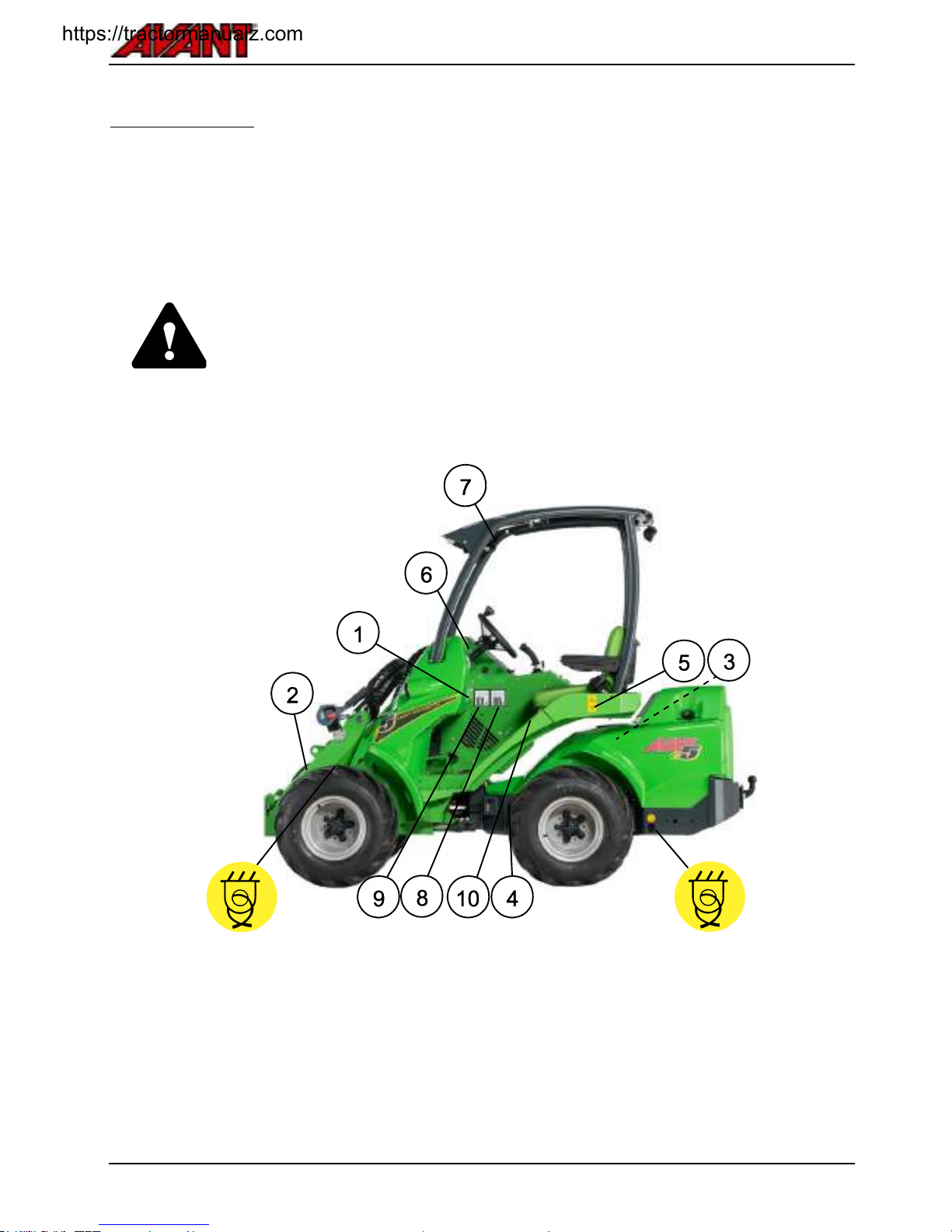
Main parts of the loader
Following picture shows the main parts of the loader:
1. Front frame
On the front frame are mounted: driver’s seat,
operating controls, parking brake, hydraulic control
valves, hydraulic oil tank, auxiliary hydraulics outlet,
front wheels, hydraulic motors and the loader boom
with attachment coupling plate.
2. Back frame
On the back frame are mounted: battery pack,
electric motors, integrated charger and its socket,
hydraulic pumps, rear wheels, hydraulic motors, and
counterweights.
3. Articulation joint
Articulation joint connects the front and back frame.
The loader is steered hydraulically by the steering
cylinder which is mounted between the front and
back frames. Hydraulic hoses and electric wires are
conducted through the articulation joint.
4. Loader boom
Loader boom is mounted on the front frame and is
controlled with control lever from the driver's seat.
The attachment coupling plate is mounted at the end
of the boom. The boom is telescopic, extending 600
mm hydraulically. The boom can be fitted with a
hydraulic self-levelling system
5. Attachment coupling plate
Attachments are mounted on the attachment
coupling plate. The locking pins on the plate can be
operated manually (standard) or hydraulically
(option).
6. Auxiliary hydraulics outlet
The hydraulic hoses of hydraulically operated
attachments are mounted on this outlet. The outlet is
equipped with the multi connector quick coupling
system and is double acting: it has two pressure
lines and one tank line, see page 61. If the loader is
equipped with the optional Attachment control switch
pack, its electric socket is integrated in the multi
connector.
In addition, as an option, it is also possible to install a
double-acting auxiliary hydraulics outlet in the front.
The quick coupling of this extra outlet will be located
under the multi connector.
7. ROPS safety frame
ROPS frame (Roll-over protective structure)
complies with the standard ISO 3471:1994 with
Amendment 1:1997 and Technical Corrigendum
1:2000 for a maximum machine configuration mass
of 2720 kg.
8. FOPS canopy
FOPS canopy (Falling objects protective structure)
mounts on the ROPS. It meets the ISO 3449:2005
(1365 J) criteria.
.
..
https://tractormanualz.com
Avant e5
19
.
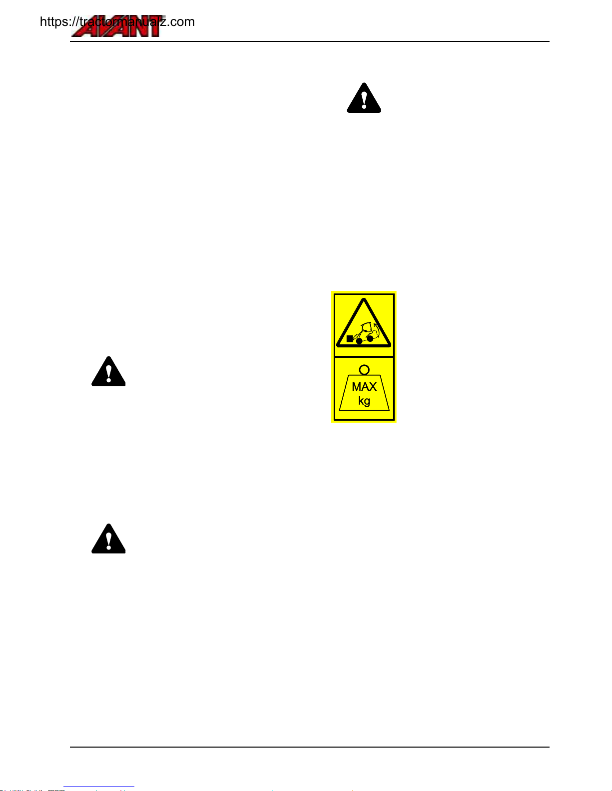
Signs and decals
Shown in the figure below and listed on the following page are the labels and markings, which must be visible on
the equipment. Replace any warning label which has become unclear, or has detached completely. New labels are
available via your retailer or contact information provided on the cover.
Before applying a new decal, clean the surface from dirt, dust, grease, or other material. Peel small portion of the
decal backing paper and apply exposed adhesive to cleaned surface, aligning the decal properly. Peel rest of
backing paper and press with hands to smooth out the decal.
The warning labels contain important safety information and they help to identify and
remember the hazards related to the equipment.
Make sure that the following signs and decals are clean, undamaged and readable. If any
of these decals is missing or is unreadable it should be replaced without delay. Ask for
new decals from your local Avant dealer.
https://tractormanualz.com
Avant e5
20
.
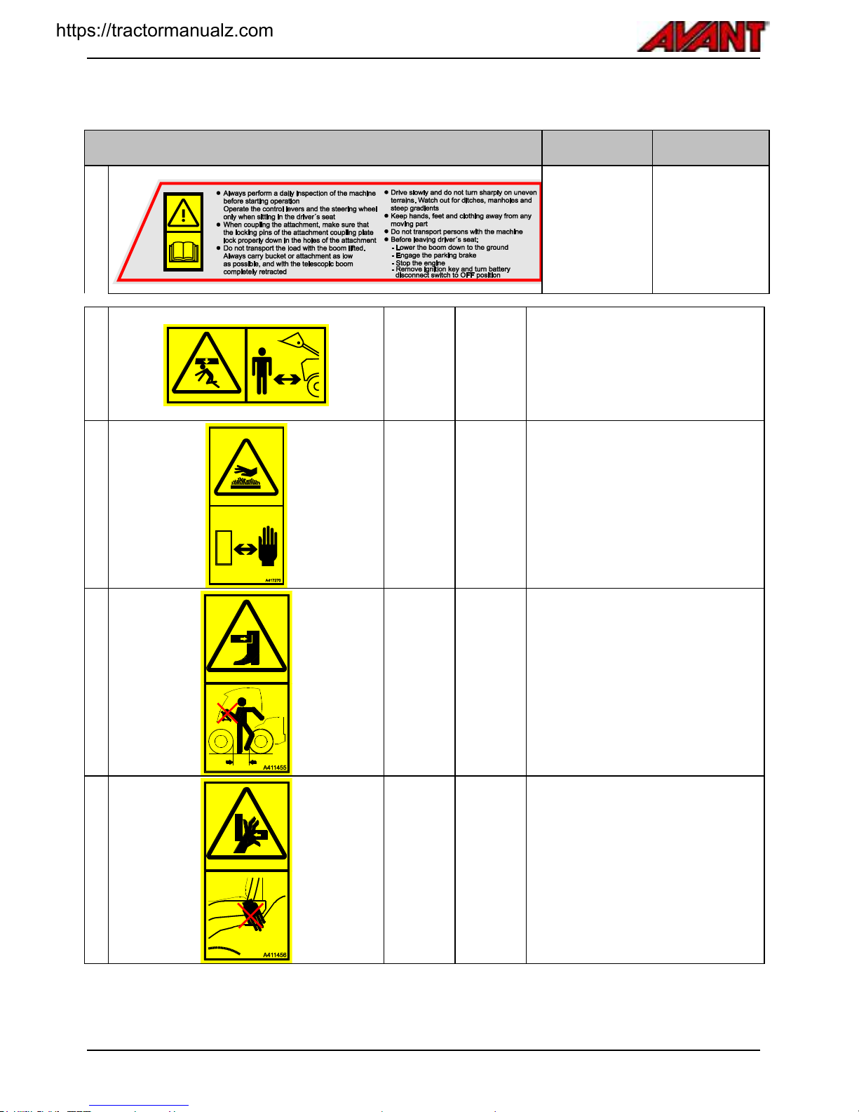
Table 2 - List of safety labels and markings on the machine
Label
Location
Product code
1
Below steering
wheel
A414690
2
Boom, on
both sides
A417273
(2 pcs)
DANGER
Lowering of loader boom can crush,
causing death or serious injury.
Keep out from the danger zone of the
machine.
3
Near
electric
motors
A417270
WARNING
Risk of burns - Extremely hot surfaces.
Keep clear.
Allow loader to cool completely before
maintenance.
4
At loader
entry point
A411455
WARNING
Risk of crushing - Small gap between
tyres of articulated loader. Do not grip
the steering wheel from outside the
machine or when getting into the
driver’s seat to prevent moving of the
wheels.
5
At loader
entry point
A411456
WARNING
Risk of crushing - Keep hands and feet
within the driver's area.
https://tractormanualz.com

Avant e5
21
Table 2 Continued - List of safety labels and markings on the machine
Label
Location
Product
code
Message
6
Next to
steering
wheel
A420354
CAUTION
Using the parking brake while machine
is moving may cause locking of wheels
and sudden stop.
Always engage the parking brake after
stopping the machine first. The parking
brake should be used to stop the
machine only in emergency. Repeated
use while driving will damage the
brakes.
Table 3 - Information labels
Label
Location
Product
code
Message
7
ROPS
frame
A420726
ROPS/FOPS Approval
8
Right
panel near
driver's
seat
A43600
Sound pressure level 88 dB(A) at
driver's seat
9
Right
panel near
driver's
seat
A411047
Sound power level 101 dB(A)
2000/14/EC
10
Front
panel
below
driver's
seat
A415780
Correct type of hydraulic oil
https://tractormanualz.com
Avant e5
22
.
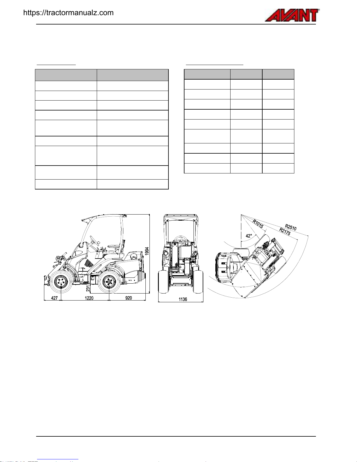
Technical specifications
Dimensions
General dimensions
Length
2550 mm
Width
1130 mm (with standard tyres)
Height
1985 mm (with standard tyres)
Mass (empty)
1600 kg
Tyres
Standard:
23 x 10.50-12" TR / GR
Lifting height
2820 mm
Max reach
1100 mm (distance from
standard front wheels to quick
coupling plate)
Turning radius,
inside/outside
995 mm / 2050 mm
Ground clearance
200 mm
Height and width
Tyre
Width
Height
23 x 8.50-12" TR
1080 mm
1980 mm
23 x 10.50-12" TR
1130 mm
1985 mm
26 x 12.00-12" TR
1290 mm
2013 mm
320/60-12" HD TR
1290 mm
2013 mm
27 x 8.50-15" TR
1030 mm
2026 mm
26.5 x 14.00-12"
TR
1420 mm
2020 mm
23 x 8.50-12" GR
1080 mm
1980 mm
23 x 10.50-12" GR
1130 mm
1895 mm
26 x 12.00-12" GR
1290 mm
2013 mm
.
..
.
..
https://tractormanualz.com

Avant e5
23
.
General specifications
e5
Category
Earth-moving machinery / Loader /
Compact loader EN ISO 6165
Product code
A21714
Drive system
Hydrostatic 4WD
Tipping load ISO 14397-1
(see also page 27)
970 kg
Rated operating capacity
480 kg
Pulling force
Static min 640 daN
Auxiliary hydraulics
*See also page 24
Max 18,5 MPa (185 bar)
Max flow
Front: 30 l/min
Hydraulic pumps
2
Auxiliary hydraulics
Standard: Faster multiconnector system on front
Attachment coupling
Avant quick coupling attachment plate
Hydraulic oil capacity
<HydroilC_e5>
Hydraulic oil type
ISO VG 46, mineral oil only
Sound pressure level
2000/14/EC Lp, ISO 6396
88 dB(A) dB(A)
Sound power level
2000/14/EC Lp, ISO 6395
101 dB(A) dB(A)
Hand-arm vibration, total
< 2,5 m/s2
Whole-body vibration, max.
< 0,5 m/s2
Electric system and battery
e5
Battery type
Lead acid battery pack
Battery product code
66390
Stored energy
11,5 kWh
Capacity
240 Ah
Voltage (nominal)
48 V
Electric motors
2
Battery cycle life
1500 cycles (estimate). See page 64
Control system and accessories
12 V / 22 A DC-DC converter
Charging system
Integrated charger
Mains current plug for charger
Schuko, grounded
Charger voltage and current
See page 66
Charging current
Controlled by charger, max 40 A ,48 v / 10 A, 230 v
https://tractormanualz.com

Avant e5
24
.
Auxiliary hydraulics oil flow
The graph below shows auxiliary hydraulics output
flow at different rpm levels of the electric motor. The
rpm of electric motor of the auxiliary hydraulics pump
is controlled with the hand throttle lever.
Some attachment may work optimally at certain flow
level, use the graph to estimate correct rpm setting.
The hand throttle lever controls
only the auxiliary hydraulic pumps.
The position of the hand throttle
lever does not affect the speed or
pushing power of the drive system.
Keep the rpm setting as low as
possible to smoothly operate the
attachment to conserve energy.
Pull the throttle lever back when
not operating an attachment.
Maximum auxiliary hydraulics oil
flow cannot be used with all
attachments. Check correct rpm
level for each attachment with the
help of this graph and the
Operator's Manual of each
individual attachment. Attachment
may get damaged, run too fast, or
it may be difficult to control
precisely when oil flow is too high.
.
Drive speed and pulling force
Tyre
Drive speed
Pulling
force
e5
TR
23 x 8.50-12" TR
9 km/h
100 %
23 x 10.50-12" TR
9 km/h
100 %
26 x 12.00-12" TR
9 km/h
85 %
320/60-12" HD TR
10 km/h
80 %
27 x 8.50-15" TR
10 km/h
80 %
26.5 x 14.00-12" TR
11 km/h
75%
e5
GR
23 x 8.50-12" GR
9 km/h
95 %
23 x 10.50-12" GR
9 km/h
100 %
26 x 12.00-12" GR
9 km/h
85 %
* The maximum speed of the loader is the highest
speed that can be achieved in optimal conditions.
Load distribution, tyre pressures, ground surface,
and many other conditions influence the maximum
speed.
** The pulling force depends on the size of the tyres.
In the table pulling force with each tyre model is
listed as comparison with the standard tyres (100 %).
https://tractormanualz.com
Avant e5
25
.
Tyres
The loader can be equipped with different type of tyres for different operating conditions. Grass pattern (GR) tyres
will damage the ground surface less than tractor (TR) tyres, but provide less traction.
Tyre
Tread
pattern
Code
Fill
pressure
Fits with fenders
Fits with snow chains
Front
Rear
SD
HD
27 x 8.50-15"
TR
65414
4,2 bar - -
65723
-
23 x 8.50-12"
TR
65995
3,4 bar x x
64746
64455
23 x 8.50-12"
GR
65994
4,6 bar x x
64746
64455
23 x 10.50-12"
TR
65997
2,5 bar x x
-
64745
23 x 10.50-12"
GR
65996
3,0 bar x x
-
64745
26 x 12.00-12"
TR
65739
3,4 bar x x
-
64973
26 x 12.00-12"
GR
65212
3,4 bar x x
-
64973
320/60-12" HD
TR
65224
4,0 bar x x
-
65603
26.5 x 14.00-12"
TR
65787
1,8 bar - -
-
-
* When using the 26,5x14.00-12" tyres (code 65787), use of 40 mm wheel spacers is mandatory to fit these tyres.
See more information below.
For the best stability and controllability, always use
the largest tyres possible. Tyres that are narrower
than the standard tyres are intended for special
purposes only with width restriction on the machine.
Use only tyres and rims that meet the original
specifications and dimensions to avoid potential
issues with load capacity, tyre size, or bearing load
on drive motors. Special tyres, such as studded
wheels may also be available. Consult your dealer
for further information.
Use widest tyres possible
WARNING
Risk of tipping over - Make sure
tyres are not damaged. Loss of
tyre pressure can cause loader to
tip over. Make sure there are no
visible damages on tyres. Keep
tyre pressure within
recommendations.
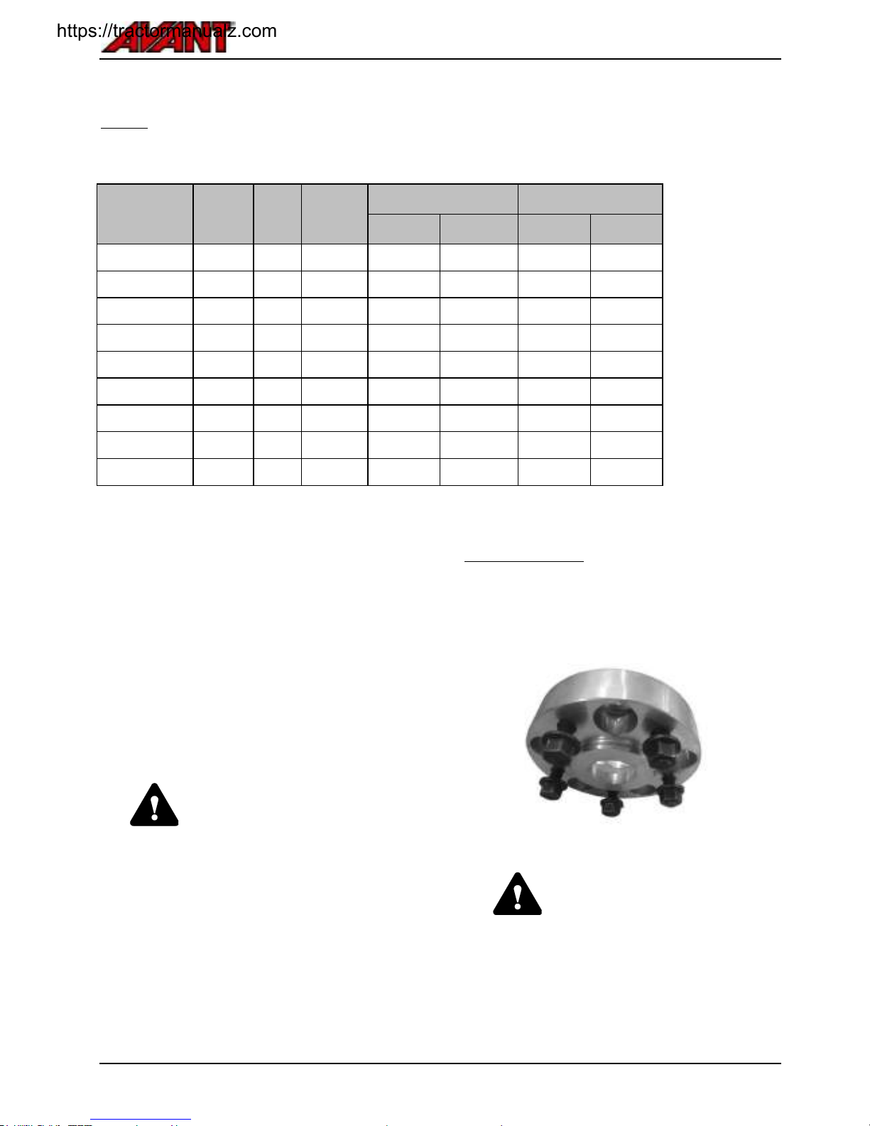
Wheel spacers
The wheels can be fitted with spacers that increase
the width of the loader for better stability. The
spacers A417486 are 40 mm thick. They must be
installed in order to fit the wide 26.5x14.00-12" tyres.
WARNING
Wheel spacers improve the lateral
stability of the loader. Do not
remove the wheel spacers unless
operating the loader on flat areas,
where the total width of the loader
must be reduced to as narrow as
possible.
https://tractormanualz.com

Avant e5
26
Use only spacers recommended by
the manufacturer. Too thick spacers
may damage the hydraulic motors.
Contact your Avant dealer for more
information.
Snow chains
Snow chains available at time of print of this manual
are listed in tyre table above. When using snow
chains, the fenders must be removed when using
larger tyre models.
There are two types of snow chains. See the table on
page 25 for a list of chains that are available for
the tyre size of your loader.
SD HD
Check that snow chains fit without hitting any part of
the loader. Check also that the snow tyres will fit
when the loader is turned to maximum articulation.
.
Ballasted tyres
Some tyres can be filled with special type of heavy
foam that creates additional counterweight. The filled
tyres are also useful in area where frequent tyre
puncture with normal tyres would be expected.
When driving with a loader that has ballasted tyres,
the acceleration and stopping distances may be
increased.
Ballasted tyres do not have air pressure inside them
and do not require air pressure checks.
CAUTION
Ballasted tyres are heavy - Handle
ballasted tyres with care. Filling of
tyres should be left to professional
tyre service.
When the loader is equipped with ballasted tyres, the
following symbol must be applied to a visible location
on the loader frame near tyres. If you replace the
tyres and install normal tyres, make sure to also
remove this label.
https://tractormanualz.com

Avant e5
27
.
Tipping load
Tipping load is the load at which the rear tyres lose
contact with the ground and the loader starts to tip
forward. A tipping load chart is shown on the next
page. The tipping load depends on many factors,
and the chart shows the influence of the position of
the loader boom.
The lifting capacity and the stability of the loader are
at the best, when:
the loader frame is kept straight
the centre of gravity of the load is as close to the
loader as possible
counterweights are fitted to the loader
swinging of the load is prevented and all controls
are used in a calm and careful manner
There are many influencing factors that affect the
stability of the loader in practise. Use the load chart
and ROC table to estimate the load handling
capacity of the loader. Observe the instructions and
information given in this manual.
See also page 50 for more information about safe
handling of heavy loads and page 51 for a list of
typical factors that influence the stability of the
loader.
.
WARNING
Risk of tipping over - Follow
safety instructions. The lifting
capacity of the loader is limited by
the possibility of tipping around the
front axle.
The operator must pay attention to
safe operating conditions
whenever handling loads.
.
..
WARNING
All counterweights affect
stability - Also the driver. Always
keep in mind: If the driver leaves
the machine, tipping and max.
loads are reduced respectively.
The indicated tipping loads and the ROC table are valid, when:
The ground is firm and level
Loader is stationary or driven max 2 km/h, with smooth and slow control movements
Driver 75 kg is seated on the driver’s seat
Load is distributed evenly on pallet forks, with the load centre of gravity at 400 mm from the vertical part of
pallet fork arms. The weight of the fork attachment is taken into account in the indicated load values
https://tractormanualz.com

Avant e5
28
.
Tipping load - load chart
With the load diagram below, you can estimate the
load handling capability of the loader.
The tipping load depends according to the distance
between the centre of gravity of the load and the
front axle of the loader.
The diagram represents the forward stability only. It
does not refer to maximum available lift force.
.
..
.
WARNING
Avoid overloading the loader Know the load and lifting
capacity of the loader.Heavy load
can cause tipping over when
moving the load. The diagram is
valid only on firm and level ground,
with the conditions listed above.
When the boom is moved to
another position, the load can
exceed tipping load and loader can
tip over.
Load chart e5
How to read the load chart
a Tipping load with the loader frame
in straight position.
b Tipping load with the loader frame
in maximum articulation.
ROC (Rated operating capacity),
defined as 60 % of tipping load for
pallet forks.
Example: If the centre of gravity of the
load is 970 mm in front of the front axle
(400 mm from the pallet forks at ground
level)
Tipping load is about 1230 kg with a
driver weighing 75 kg, and with the
articulated frame turned to max
articulation.
When lifting to horizontal position,
the tipping load is reduced to about
830 kg.
This means that a pallet with a total
weight of 1200 kg can be lifted just
off the ground.
.
..
https://tractormanualz.com

Avant e5
29
.
Rated operating capacity
To easily determine how much load the loader can
handle safely, a table of the tipping load and a
calculated Rated Operating Capacity (ROC) is
shown in the adjacent label. The label is also visible
from the driver's seat.
Rated operating capacity depends on type of use of
the loader:
In bucket and general application the rated
operating capacity is 50% of tipping load
In pallet fork application the rated operating
capacity is 60% of tipping load
The information shown in the table is the worst case
minimum load, with the conditions listed on page
27. Actual lifting capacity could be significantly
higher, or it may be lower, depending on terrain
conditions, available lifting force, and load
distribution. Adding or removing counterweights will
affect the indicated ROC.
Rated operating capacity label
Different loader configurations, rows in the label:
1. Loader frame in straight position, additional
180 kg counterweights fitted
2. Loader frame in straight position, standard
counterweight fitted
3. Loader frame in fully articulated position,
standard counterweight fitted
Different positions of the loader boom, columns
in the label:
1. Maximum tipping load, stability when lifting
load just off the ground with pallet forks
2. Boom lifted to horizontal position
3. Boom lifted to horizontal position, telescopic
boom fully extended (least stable position)
4. Rated operating capacity in pallet fork
application, telescopic boom retracted
5. Rated operating capacity in pallet fork
application, telescopic boom fully extended
https://tractormanualz.com

Avant e5
30
Controls and options of the Loader
Following picture shows the location of operating controls. The location and function of controls may be slightly
different in different models, see following pages.
Reference
Page
1.
Dashboard
Ignition switch
31
2.
Multi-function Display
35
3.
Charger status lights
31
4.
Signal horn switch
Control switches (see below)
5.
Control lever of boom and bucket
32
6
Auxiliary hydraulics control lever
32
7.
Boom telescope control
33
8.
Hand throttle lever
34
9.
12 V outlet (max 15 A)
35
Controls in footwell
A
Drive pedal, right: drive forward
(see below)
B
Drive pedal, left: drive backward
(see below)
.
..
Switches on the panel
NOTE: Some of the
switches presented
here are for optional
equipment and might
not be installed on
the loader.
The position of the
switch may be
different than shown
in here.
Auxiliary
hydraulics outlet
selection switch
Optional
equipment
See page 41
Extra work lights
on the ROPS
frame, 2 front, 1
rear
Optional
equipment
Drive mode /
speed range
selection switch.
See page 47
Warning beacon
Optional
equipment
See page see
page 37
Operation mode
selection switch
See page 46
Hydraulic locking
pins, attachment
coupling
Optional
equipment
See page 58
Parking brake
See page 35
Windscreen
wiper and
washer (CAB L
option)
see page 38
Emergency
blinker
Optional
equipment
https://tractormanualz.com

Avant e5
31
.
Dashboard
Dashboard e5
On the dashboard there is the ignition key, and
additional switches and indicator lamps.
The multi-function display shows information about
battery charge level, hours of use, and diagnostics
related trouble codes. The display is backlit
whenever the ignition key is switched on. The hour
metre runs whenever the electric motors are running.
Indicator lights
Symbol
Colour
Remarks
1
Not in use in this loader model
2
Red
Hydraulic oil cooler fan fuse
Hydraulic oil cooler malfunction.
See page 85
3
Blue
High beam headlights on
Road traffic light kit only
4
Green
Turn signal indicator
Road traffic light kit only
5
Green
Seat heater on
6
Yellow
Boom floating on
(optional equipment)
Boom floating See page 39
7
Green
Work lights on
Work light switch at lower part
of dashboard
8
Not in use in this loader model
Charging indicator lights
Symbol
Colour
Remarks
9
Green
Battery fully charged
10
Yellow
Charge in progress
Full charge will take about 4
hours. Battery charge process
See page 63.
11
Red
Battery not charging
Charging system has detected
a fault and has prevented
charging to protect the battery
from damage, see
troubleshoot on page 87.
.
..
.
..
Switches on the dashboard
LOCK
Switch not in
use with this
loader model
Standard work
lights
Boom floating
Seat heater
https://tractormanualz.com

Avant e5
32
.
Control of loader boom, auxiliary hydraulics and other functions
Most of the functions of the loader are controlled with the controls at the right side of the operator: Boom and
bucket movements, auxiliary hydraulics (attachments), auxiliary hydraulics pump speed etc., depending on loader
model. Following paragraphs show the different functions.
1. Control lever of boom and bucket
The loader boom and bucket are controlled with the multi-function lever sideways (tilt) and back & forward (boom
up & down).
Pull backward to lift the
boom
Push forward to lower the
boom
Push left to raise the tip of
the bucket (filling)
Push right to lower the tip of
the bucket (emptying)
2. Control lever of auxiliary hydraulics (hydraulically operated attachments)
Hydraulically operated attachments are connected to the loader using the multi connector system, for more
information see page 61.
Operation directions depend on the attachment used.
When using an attachment for the first time, carefully
move the lever to test and check the operating direction
of the attachment.
For continuous operation of rotating attachments, turn to
direction 1 and turn to locking position.
If operating the buttons of the electric joystick, this lever will
not move. Either the lever or the buttons can be used to
control the attachment as needed.
When you operate attachments that require continuous flow,
such as attachments with hydraulic motors, it is important to
have the control lever in fully engaged position. If the control
valve is not fully open, restricting the flow of hydraulic oil,
hydraulic system may overheat quickly.
If necessary, adjust the locking plate so that the lever is
locked to fully open position.
https://tractormanualz.com
Avant e5
33
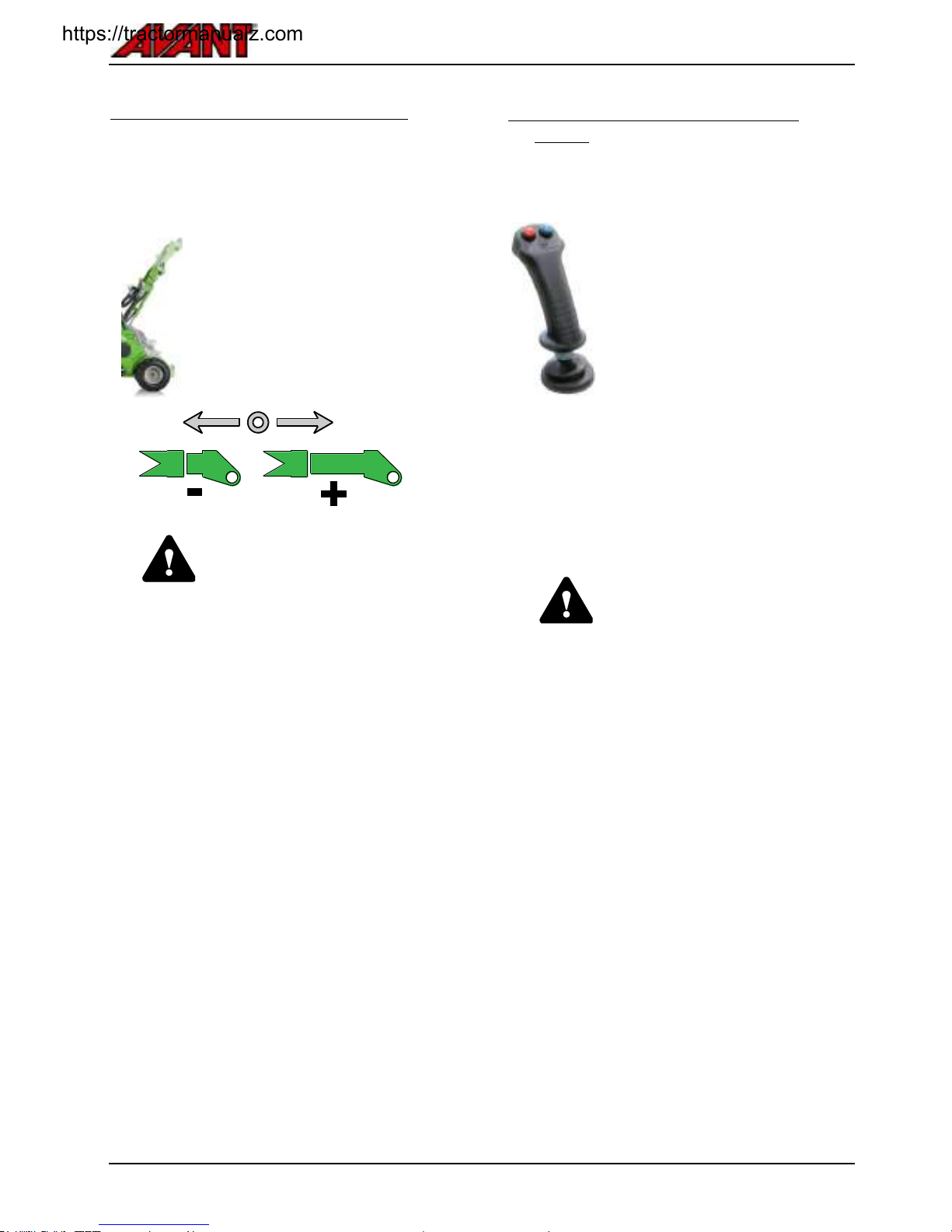
3. Telescopic boom control lever
The telescopic boom makes many tasks easier, also
those that do not involve lifting. You can, for
example, push material further with a bucket, reach
into difficult areas, and improve visibility to the work
area with some attachments.
The telescopic boom can be
extended by 600 mm. It increases
the maximum lifting height by 485
mm.
Turn the control lever of the
telescopic boom to the right to
extend the boom, and turn to the
left to retract it.
WARNING
Risk of tipping over - Extended
boom can cause the loader to tip
over. Use telescopic boom with
caution. The stability of the loader
depends on the distance of the
load from the front of the loader.
When you extend the boom, you
increase the effect of the weight
and reduce safe handling capacity.
See pages 27 and 50 for
further instructions about tipping
load and safe material handling.
.
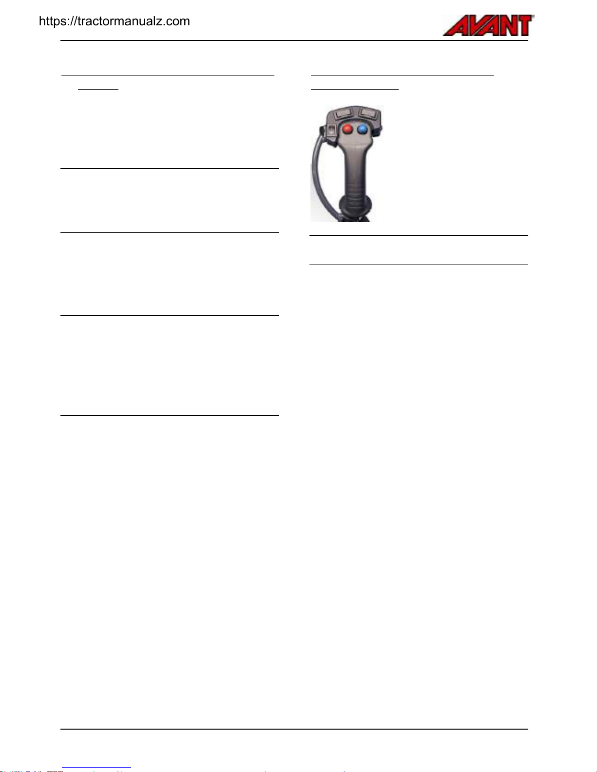
4. Joystick - 6 function (optional
extra)
If the loader is equipped with the optional 6 function
joystick, the auxiliary hydraulics can be controlled
with electric buttons on the joystick:
Push and hold either button to
operate hydraulic feature of the
attachment. While holding a
button, the manual control lever
also moves to corresponding
direction.
The operation of the buttons
depends on the attachment,
see Operator's Manual of the
attachment.
Release buttons to stop.
Make sure the manual control
lever is not locked when
operating electric joystick.
CAUTION
Avoid abrupt movements of an
attachment - Use electric
buttons with caution. When you
use certain attachments with the
electric joystick buttons, the
attachments can move abruptly.
This can cause falling of material
from the attachment, loss of
stability, or damage to attachment.
https://tractormanualz.com
Avant e5
34
.
5. Hand throttle lever for pump RPM
control
The electric motors run when the ignition key is
switched to ON position, and when the operator is
seated on driver's seat, or other operating mode is
selected. See more information about the operator
presence control on page 46.
The hand throttle lever controls the output and
rotation speed of the auxiliary hydraulics pump. The
drive system is controlled with drive pedals and the
hand throttle lever will influence only the auxiliary
hydraulics pump, not the drive system.
Push the lever forward to increase rpm of
hydraulic pumps and increase auxiliary
hydraulics oil flow
Pull backward to reduce rpm of hydraulic pumps
and to decrease auxiliary hydraulics oil flow
The auxiliary hydraulics pump will also provide
pressure for the release of the parking brake, and to
flush the drive circuit. This is why the auxiliary
hydraulics pump will operate whenever the loader is
ready to be driven. However, to conserve battery
energy, adjust the speed of the pump to a minimum
setting whenever not actively using a hydraulic
attachment.
As the hand throttle lever controls the output of
hydraulic flow, this will also influence the speed of a
hydraulically driven attachment. In general, the more
throttle, the faster the attachment operates. Make
sure not to exceed max. allowed oil flow of the
attachment, see Auxiliary hydraulics oil flow on
page 24.
.
Attachment control switch pack
(optional extra)
If your loader is equipped with
the optional attachment control
switch pack, the electric
functions of an attachment can
be controlled with the extra
buttons fitted on the joystick.
Check the operator's manual of the attachment to
see how to control each attachment.
When the loader is equipped with the Attachment
control switch pack, the Multi connector ( see page
61) includes also an electric socket, so that the
hydraulic hoses and the electric cable of an
attachment with electric function(s) can be coupled
simultaneously with the multi connector system.
https://tractormanualz.com
Avant e5
35
.
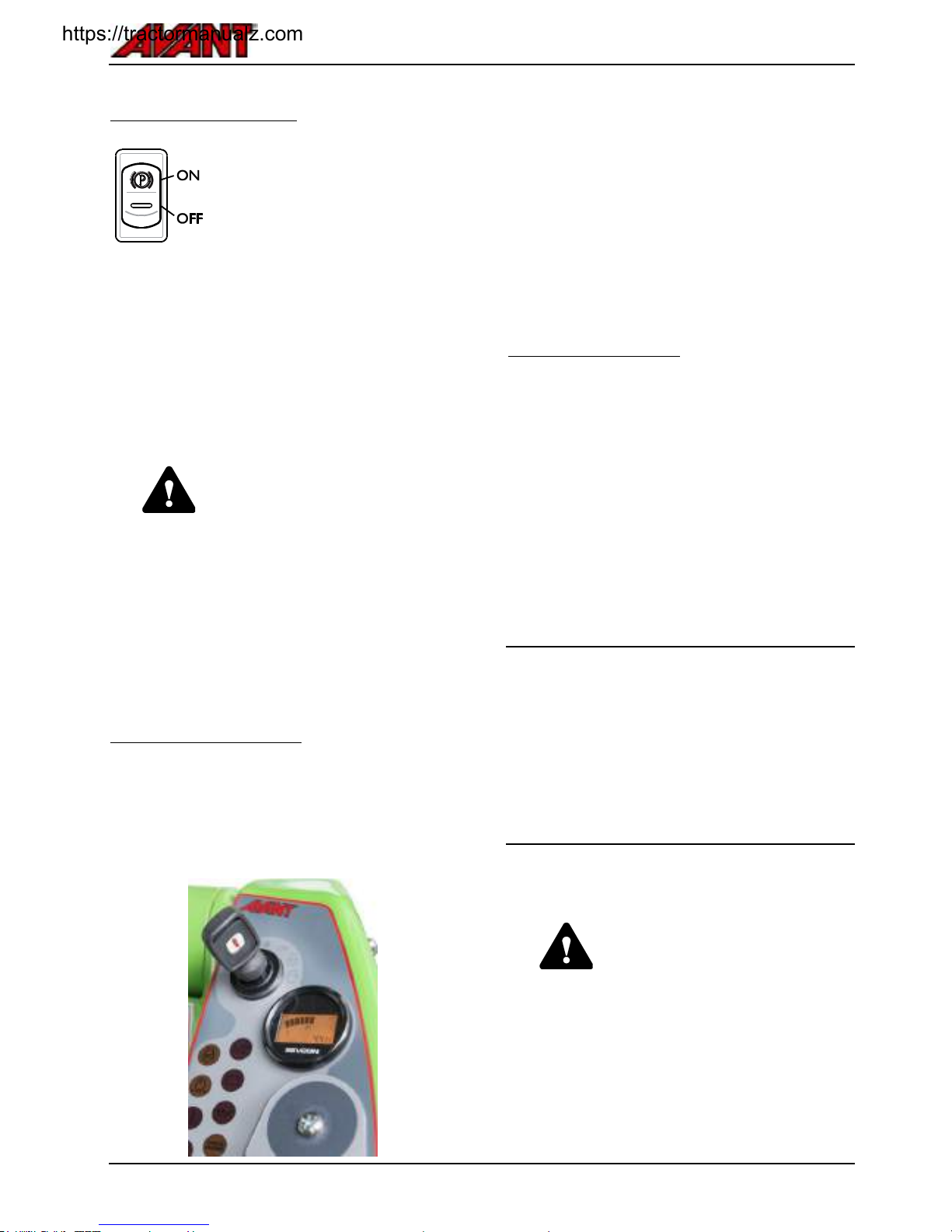
Parking brake switch
Switch on the parking brake
whenever leaving the driver's
seat.
The loader is equipped with a
brake system that locks the rear
wheels. The parking brake is
activated when loader is switched
off or when hydraulic pressure is
otherwise lost due to a failure.
Parking brake can be released
only when the loader is running
and the auxiliary hydraulics pump
creates enough pressure for the
brakes to release.
CAUTION
Using the parking brake while
machine is moving may cause
locking of wheels and sudden stop.
Always engage the parking brake
after stopping the machine first.
The parking brake should be used
to stop the machine only in
emergency. Repeated use while
driving will damage the brakes.
Multi-function display
The multi-function display shows the following
information when the loader is in normal operating
mode:
Battery charge level
Operating hours (symbol with letter p visible)
During start-up the display will quickly cycle through
the following:
Total pump run time
Total time of how long key has been in position
ON
Total traction pump run time
In case the control system of the loader has detected
a fault in the control system of the loader, the display
will show a diagnostics fault code. For more
information about diagnostics codes, see page 86.
Electric 12 V outlet
When operating attachments with electric features,
the electric harness of the attachment can be
connected to the 12-volt outlet on the dashboard.
The standard type outlet is powered when ignition is
switched on. Maximum current: 10 A.
The total 12 v electricity output capacity of the loader
is limited. This available power shared between
lights, control system, and all additional accessories,
such as seat heater etc. High-current accessories
should not be connected to this electric socket. Keep
in mind that all additional electric equipment reduce
the battery run time. Switch off all unnecessary
equipment.
There is an electric socket for the attachment on the
multiconnector if the loader is equipped with the
optional attachment control switch pack. In this case
the electric plug of the attachment will be connected
simultaneously with its hydraulic hoses. In case there
is no electric plug on the multiconnector of the
attachment, use the separate electric harness to
connect to the regular 12 V outlet of the loader. You
can also contact your Avant dealer to fit an electric
plug to the attachment multiconnector.
Risk of fire and electric shock - Never connect
any device directly to the battery.
WARNING
The battery is able to produce high
electric current that can burn or
injure severely, and even cause
death. Short-circuit can cause the
battery to burn or explode. Never
connect any device directly to the
48 volt systems of the loader.
https://tractormanualz.com

Avant e5
36
.
Seat - Seat belt and seat adjustments
WARNING
The seating capacity of the loader
is one person only. Never carry
passengers on part of the loader or
with any attachment.
Always use seat belt while driving. Clean the seat
belt regularly with a sponge, warm water, and soap.
Use compressed air to clean the buckle.
Replace the seat belt if any damage is seen, or if the
seat belt is exposed to high load or chemicals.
Seat adjustments
Make sure that the seat is properly adjusted for easy
reach to the operating controls and to keep vibrations
transmitted by the seat at minimum. Long term
exposure to vibrations may cause health effects.
Also, as far as possible, keep the operating terrain in
good condition to minimise vibrations.
Suspension seat
The suspension seat has the following adjustments:
1. Seat position
The distance of the seat from the steering
wheel can be adjusted with the lever which is
located under the front edge of the seat
2. Arm rest angle adjustment
The angle of the arm rest can be adjusted by
turning the roller under the arm rest
Adjust the arm rest to position which allows to
use controls of the loader comfortably while
keeping arm on the arm rest.
3. Suspension adjustment
By turning the knob counter-clockwise
suspension gets harder, by turning it clockwise
the suspension gets softer
4. Angle of the back rest
The angle of the back rest can be adjusted by
pulling the lever
Seat heater
The suspension seat is equipped with an electric
seat heater. Seat heater switch and its indicator lamp
are situated on the dashboard.
https://tractormanualz.com

Avant e5
37
.
Lights
Work lights
The loader is equipped with standard work lights at
the front of the loader, which are controlled with a
switch near the ignition switch.
If the loader is equipped with the optional road traffic
light kit, the standard work lights are replaced with
road headlights.
Extra work light kit (option)
The loader can be equipped with extra work lights,
making it easier to work in low light. The lights are
operated with the switch on the control panel
Switches on the panel.
Warning beacon (option)
The beacon can be removed quickly by loosening its
retaining screw and then by pulling the beacon out.
Place the protective seal on the beacon stand to
prevent water entering and damaging the
connectors. Handle beacon with care. The beacon is
sealed and its inner components cannot be replaced
or repaired by user.
Beacon includes high-voltage
components. Do not use or repair
damaged beacon, replace with new
one.
https://tractormanualz.com

Avant e5
38
.
CAB L (optional extra)
The e5 can be equipped, as an option, with cab L.
Shown in this chapter are the controls and features
that differ from the standard ROPS model.
Windscreen washer and wiper
On machines with cab L, the windscreen washer is
operated with a switch on the switch panel. The
switch has the following functions:
2.
1.
0.
Spray washer fluid
Continuous operation
Off
The windscreen washer fluid tank is located on under
the access step of the loader. The filler opening is on
the access step.
Cab Safety
Make sure visibility from the cab is adequate. Keep
all window panels clean and clear of snow, ice, etc.
Familiarise yourself with the special drive features
and space needs of this articulated loader, equipped
with cab, on a flat, even and open place.
Remember that, when turning, the cab extends
beyond the turning radius of the wheels. This should
be taken into consideration especially when driving in
confined spaces, in order that the rear of the cab will
not get damaged.
In case the normal
opening on the left side of
the loader is blocked, the
windscreen can be used
as an emergency exit.
If necessary, the
windscreen can be broken
with the emergency
hammer located in the
cab.
https://tractormanualz.com

Avant e5
39
.
Options
This section shows how to use correctly and safely the options that are installed to your loader.
Most of the options can be installed to your loader by your Avant service point. Contact your dealer or service point
for more information and availability of the options.
Boom self-levelling
Self-levelling is a system that
keeps the attachment tilted in
same position when lifting or
lowering the boom.
Self levelling is an automatic
hydraulic system. There is a
levelling cylinder on the left side
of the boom which follows the
movements of the loader boom
and keeps the attachment level.
NOTE: Self levelling is disabled
when the boom floating is
switched on.
When the attachment tilt is turned
to either extreme position, the
boom lift cylinder will have to work
against the pressure of the self
levelling cylinder.
To prevent extreme stresses to the
loader boom, operate the bucket
tilt control to move out from
extreme tilt before lifting or
lowering the boom.
Boom floating
The boom floating is a system that allows an
attachment to follow the surface of the ground. The
floating system releases the lift cylinder and allows it
to float upwards from the position where it is when
boom floating is switched on. When boom floating is
switched on, it is not possible to push down with the
boom.
To switch on the boom floating:
1. Lower the attachment on the ground to the
position where it will be used
2. Switch on the floating with a switch on the
dashboard, see page 31.
Boom floating indicator light on the dashboard
is lit when the system is switched on.
During boom floating, some air may become sucked
into the lift cylinder. To avoid unexpected or
inaccurate movements of the boom, the air in
cylinders must be removed by moving the boom to
extreme lift positions after switching off the floating
system.
After use of boom floating
WARNING
Risk of unexpected movements Move the loader boom after you
have switched off the boom
floating to remove air from
cylinders. During the use of boom
floating air can get trapped in the
hydraulic system. This can cause
inaccurate movements of loader
boom and the boom can even
move down.
Therefore the boom and
attachment coupling plate should
always be moved to extreme end
positions after switching off boom
floating.
Self levelling is disabled when the
boom floating is switched on.
Boom can't be pushed down with
hydraulic force, when floating is on.
Use boom floating only when
necessary.
https://tractormanualz.com
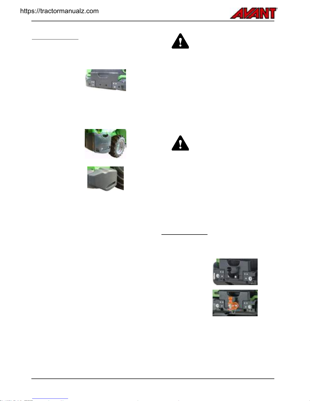
Avant e5
40
.
Counterweights
Additional counterweights can be installed to
increase the stability of loader when handling heavy
loads or attachments.
1.
29 kg individual
weights A35957
Max 3 pcs.
If you install a
trailer coupling,
only one extra
weight can be
used.
2.
80 kg side weight
kit A36401
One 40 kg weight
to both sides of
the loader.
3.
180 kg side
weight kit A49063
One 90 kg weight
installed to both
sides of the
loader.
The side weight kits will not increase the total width
of the loader (depending on tyre model).
e5 uses its battery pack as a standard
counterweight. The 170 kg rear counterweight,
available for some loader models, cannot be installed
to e5 because of different rear frame construction.
Make sure that the weight on the trailer is distributed
correctly so that the trailer cannot cause an upward
lifting force on the trailer coupling. It is recommended
that you keep an attachment fitted at the front of the
loader to add weight to the front of the loader.
WARNING
Risk of loss of control of loader Too much counterweight can
make the front of the loader too
light. If you install too much
counterweights to the loader, the
front wheels of the loader will be
easily lifted from the ground. This
will make steering of the loader
difficult. If counterweights are fitted
to handle a certain attachment,
remove counterweights if driving
without an attachment.
CAUTION
Risk of sudden loss of stability Always install any
counterweight firmly.
Counterweight can fall from the
loader on uneven ground or after
hitting a wall or other structure.
Tighten all fastening screws. After
installing the 180 kg side weight
kit, remove their lifting slings from
the weights to prevent their use as
tie down points.
Trailer coupling
The loader can be equipped with a trailer coupling for
towing of light trailers. There are two types available:
1.
50 mm ball hitch
A417323
2.
50 mm ball hitch
with towing pin
A417337
Trailer coupling can be mounted either directly on the
rear bumper or on the extra back weight.
Max. allowed vertical load 1,5 kN
Maximum towing load is 10 kN.
https://tractormanualz.com

Avant e5
41
Make sure that the weight on the trailer is distributed
correctly so that the trailer cannot cause an upward
lifting force on the trailer coupling. It is recommended
that you keep an attachment fitted at the front of the
loader to add weight to the front of the loader.
DANGER
Overload on the trailer coupling
may cause loss of control. Tow
only light garden trailers. Make
sure that the weight on the trailer is
distributed correctly so that the
trailer cannot cause an upward
lifting force on the trailer coupling.
Rear carrier
To use certain attachments, or carry extra loads at
the rear of the loader, a rear carrier is available.
DANGER
Risk of loss of control of the
loader - Never add too heavy
load on the rear. Too heavy loads
or attachment at the rear of the
loader, especially if combined with
extra counterweights, can make
the front of the loader too light.
Front wheels can lose contact from
the ground. Ensure that loader is
loaded evenly. Remove
counterweights if necessary.
WARNING
Risk of shearing of hands or
fingers and impact - Unlocked or
improperly locked rear carrier
can swing. Make sure both of the
locking pins of the rear carrier are
locked. Unlocked carrier can swing
in uncontrolled way, creating
hazards of impact, crushing, and
pinching between its linkage. If
attachment gets damaged because
of unlocked carrier, it can cause oil
spray and fire. Unlock the carrier in
controlled way and keep hands
clear from linkage.
Extra auxiliary hydraulics outlet
In addition to the standard auxiliary hydraulics outlet,
the loader can be equipped with a double acting
extra outlet. The couplers are conventional type
quick couplers.
Extra quick couplers located under the
multi-connector, at the front of the loader.
For instructions about use and how to connect or
disconnect the extra hydraulic couplings, see page
41.
You can operate either the hydraulic function
connected to the standard multiconnector, or the
function that is connected to the extra outlet.
Simultaneous use is not possible.
Reverse buzzer (option)
A reverse buzzer gives an audible signal whenever
reversing with the loader. This alarms others of an
approaching machine and thus improves safety.
https://tractormanualz.com

Avant e5
42
.
https://tractormanualz.com

Avant e5
43
Operating instructions
.
..
Always remember – safety first. Test all the functions of the loader at an open and safe
place. Make sure that there are no persons in the operating area of the machine and the
danger zone of the attachment.
.
..
DANGER
Careless operation can injure you or bystanders - Keep the loader under control at
all times. Operating a powerful loader and its attachments requires the full attention of
the operator. Do not perform distractive actions while operating, such as using mobile
devices.
.
..
WARNING
Pay attention to other machines and persons that are moving in the area. Make sure that
there are no persons in the danger zone of the loader and the attachment. The danger
zone of the loader covers the reach area of the loader boom, the turning area on the side
and in the front and rear of the loader. Always put down the load when leaving the
machine – the loader is not designed to stay with the loader boom and load lifted. Learn
how to operate the loader in a safe place.
.
..
https://tractormanualz.com

Avant e5
44
.
Starting the loader
Before starting the loader do the daily checks. See
page 73.
Adjust the seat and mirrors (if fitted) so that you have
a good working position and unrestricted field of
vision from the driver’s seat. Check that all controls
function correctly. See to it that the operating area is
safe.
Make sure you have all operating manuals available.
Read and follow all operating and safety instructions.
WARNING
If auxiliary hydraulics is switched
on during starting and there is a
hydraulically operated attachment
on the machine, the attachment
can move suddenly and cause a
dangerous situation.
Make sure that the
auxiliary hydraulics control
lever is in neutral position
during starting.
Do not actuate the
auxiliary hydraulics control
buttons on the joystick
when starting (if fitted).
The e5 loader will not start in either
of the following conditions
Electric motors will not start if
driver is not seated on driver's
seat.
When the ignition switch is
switched to position ON,
motors will start as soon as
driver is seated on the seat.
Drive functions are disabled if
either drive pedal is depressed
during start. Drive function is
enabled after release of
pedals.
.
Ignition key
The ignition key controls both the operation of the
loader and the main battery disconnect switch.
Turning the ignition switch beyond the position ON is
possible, but unnecessary.
.
..
WARNING
Prevent unintended movements
of the loader. Keep hands and
feet away from other controls of
the loader while starting. A fault
code will appear if you press a
pedal during start of the loader.
WARNING
Misuse can be dangerous Prevent unauthorised use,
remove key. Powerful loader and
its attachments can be dangerous
in the hands of an inexperienced
temporary operator. Take the key
with you to prevent unauthorised
use of the equipment.
To operate the auxiliary hydraulics
or drive pedals, you must be
seated on the driver's seat. Safety
system prevents use of hydraulic
systems, unless seated on the
seat. If you use an attachment that
is controlled from other position
than the driver's seat, see page
46.
.
..
https://tractormanualz.com

Avant e5
45
Battery disconnect switch
The loader is equipped with an electrically controlled
battery disconnect switch (main switch). The
automatic battery disconnect cuts the current
between battery and the rest of the electric system
whenever ignition key is switched to position OFF.
To switch on the electric systems of the loader, turn
the ignition key to position ON and wait for a few
seconds.
To start the loader:
1. Perform daily checks (see Maintenance &
Service on page 70)
2. Sit on the driver's seat, adjust seat, and fasten
seat belt
3. Move the hand throttle lever to idle position
4. Make sure that auxiliary hydraulics is switched
off (lever in neutral position), see page 32. Do
not press on the drive pedals.
5. Turn the ignition key to position ON
Automatic battery disconnect switch will be
switched on when ignition key is in this
position
It is possible to turn the ignition key further,
beyond the position ON. However, this has
no effect on e5 loader model.
.
..
Make sure there are no remaining
warning messages on the
multi-function display after start. If
the motors do not start after you
have turned the ignition switch to
position ON, see troubleshoot on
page 87.
.
Stopping the loader (Safe stopping
procedure)
1. Lower the boom completely down
2. Stop any attachment (move auxiliary
hydraulics control lever to neutral position,
see page 32), set hand throttle to rear position.
Place attachment firmly on the ground
3. Engage parking brake
4. Stop the motors by turning the ignition key to
the OFF position (to the left)
5. Release auxiliary hydraulics pressure (see
page 62).
6. Prevent unauthorised use of the loader. Take
the ignition key with you.
Stop if you notice any of the following:
Stop the loader to a safe state as
soon as possible if you observe any
of the following symptoms. Find out
the cause before restarting.
Battery charge level is below 10 %. Drive to
a charging location and avoid heavy load
Electric motor rpm increases and/or
decreases suddenly by itself, even if you
don't move the throttle lever, or press the
pedals
You notice sudden increase in vibration or
noise levels
Tips to increase battery life
Store the battery in recommended
temperatures
Operate the auxiliary hydraulics only at the
speed that is necessary for the attachment or
work. Too high flow will waste energy.
Always switch off the auxiliary hydraulics
when not actively using the attachments.
https://tractormanualz.com

Avant e5
46
.
Drive control
Principle of operation
The Avant e5 loader is equipped with a hydrostatic
drive system that is powered by an electric motor.
The drive pedals are used to control the motor and
the drive pump.
Use the pedals to control driving direction
and travel speed
Speed and pulling force are controlled with
the pedals. The more you press a pedal, the
faster the loader will travel, or the higher the
pulling force will be.
Choose the most suitable drive mode with
the drive/operating mode selection switch,
see page 47
The position of the Hand throttle lever controls only
the RPM of the auxiliary hydraulics system. Position
of this lever will not affect drive speed or pulling
force. The drive system works independently from
the other hydraulic circuits that are controlled with
the hand throttle lever.
When you do not actively use an attachment, keep
the hand throttle lever set to a low rpm setting to
conserve energy.
WARNING
Risk of collision or tip over - Use
low speed when you practise the
use of the loader. Familiarise
yourself with the driving of the
machine on low speed and on a
flat, even and open place. Make
sure that there are no persons in
the operating area of the machine
to avoid injuries that could result
from unintended movements.
When you have learned how to
drive with slow speed operating
mode, increase speed gradually
and learn how to drive and steer
the loader with higher drive
speeds.
WARNING
Risk of tipping over - Avoid high
speed turns. The loader can tip
over, if you turn the steering wheel
sharply while driving. Slow down
before making sharp turns. Always
control and steer the loader with
smooth movements.
Operator presence control
The loader is equipped with a safety system that
restricts the use of controls of the loader, if there is
no driver on the driver's seat. There are two
operating modes that are controlled with a switch on
the panel:
1. When control mode switch is
switched to this position,
auxiliary hydraulics can be
operated while not seated on
the seat. Drive pedals are
disabled.
This makes it possible to
operate attachments that are
controlled with their own
control systems. Those
attachments may be intended
to be operated from other
position than from the driver's
seat. See the intended use
and operating position from
the operator's manuals of
those attachments.
2. In this mode, the drive pedals
boom movements and
auxiliary hydraulics can be
used only while seated on the
driver's seat
https://tractormanualz.com

Avant e5
47
Drive pedals
Driving forward: press gently on the right
drive pedal until the machine starts to move
slowly.
To drive backward: press gently on the left
drive pedal.
When you wish to stop gently release the
pedal by lifting of your foot, and the machine
will slow and stop.
If you need stop more quickly, press the drive pedal
of the opposite drive direction. Release both pedals
as soon as the loader has stopped, otherwise the
loader will immediately start to move to the direction
of the drive pedal that is pressed.
Driving/operating modes
Operating mode selector
changes the response of the
drive pedals. The system can
be optimised for power,
maximum battery life, or
greatest accuracy of control.
The maximum pulling force is
the same regardless of the
position of the switch.
1. Power mode
Use this mode when you need high speed or
high auxiliary hydraulics output.
Battery run time may be short as result.
2. ECO mode
Use this mode for maximum battery run time.
Management of electric systems and hydraulic
flow are optimised to avoid waste of energy.
Maximum speed and acceleration are limited.
3. Slow / inching mode
This mode provides modified response to drive
pedal. This helps you to operate the loader in
tight spaces, where great accuracy is needed,
or when learning to operate the loader.
.
When you want to have a high pulling
force:
Drive pedals adjust both speed and torque.
Pushing pedal further down will increase pulling
force and speed. Press pedal only as much as
needed
The position of the driving mode switch does not
affect pulling force
The position of the hand throttle lever does not
affect pulling force or drive speed
If battery is low, and a high speed is requested
with a drive pedal, the loader may not be able to
produce maximum pulling force. Push pedal
lighter in this case
OptiDrive™
The e5 loaders are equipped with efficient Avant
OptiDrive™ hydraulic drive system as standard.
The system is designed for optimal hydraulic oil flow,
which helps to conserve energy by minimising
losses. This is achieved with the use of integrated
high efficiency Avant valve blocks and new hose
fittings.
Drive release and anti slip
Drive release valve
The hydraulic drive circuit has a built-in drive release
system, which allows the wheels on the left and right
side of the machine to roll at different speeds to
leave less tyre marks on soft surfaces. The system
automatically limits the flow of hydraulic oil between
the hydraulic motors on each side, functioning in
similar way as a limited parallel differential lock,
increasing pushing force of the loader. The system is
always engaged.
Anti-slip valve (optional extra)
If the loader is equipped with optional anti-slip valve,
the valve positively diverts oil flow between the right
and left side hydraulic motors and improves traction
on slippery and uneven surfaces. Some oil will pass
between the left and right side of the loader, and also
through hydraulic motors themselves. This means
that even though all wheels do not slip and spin
equally, all provide maximum pushing force.
https://tractormanualz.com

Avant e5
48
Allow the loader to warm up properly
Hydraulic oil temperature has an effect on the
hydrostatic drive system of the loader. When ambient
temperature is below 5º C, make sure the general
response to drive pedals is normal. If the drive feels
sluggish, allow the hydraulic system to warm up by
letting the auxiliary hydraulics pump to run at idle.
Drive carefully until the loader has reached its normal
operating temperature.
WARNING
Risk of decreased braking
power - Make sure hydraulic oil
is not overheated. When
hydraulic oil gets hot, driving
characteristics of the drive system
change. When the oil is hot and
the hydraulic oil cooler has
switched on, stopping distance of
the machine can be longer than
when the machine is cold. If the
loader is used constantly in high
ambient temperatures, hydraulic oil
type and viscosity must be suitable
for these conditions. Contact Avant
service.
WARNING
In case braking power of
hydrostatic drive system has
decreased, engage the parking
brake. The rear wheels may lock
immediately. Parking brake acts as
an emergency brake, and will also
engage in case of loss of oil
pressure. Parking brake is
intended to keep the loader
stationary and not for repeated
braking. Engage while loader
moves only when necessary.
.
Battery system in cold environment
The battery pack is less capable to supply energy in
cold environment. This sets a limit to the minimum
operating temperature where the loader can be
practically used. Operating in cold conditions will
decrease battery performance and cold, stiff
hydraulic oil will waste more energy.
The electrolyte temperature inside the battery cells
should be at least +10°C before charging. Otherwise
the battery will not recharge to completely full state.
To reach maximum battery capacity in freezing
conditions, keep the loader stored in warm shelter.
Battery will then remain relatively warm during use
and will be able to output as much energy as
possible.
https://tractormanualz.com
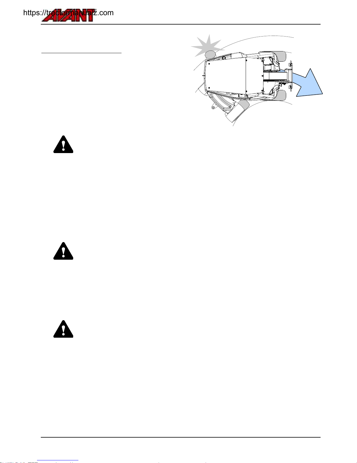
Avant e5
49
.
Steering of the machine
The machine is steered with the steering wheel. The
steering wheel is hydraulically powered. A practical
way of controlling the loader is to steer with your left
hand on the knob of the steering wheel. This way
your right hand is free to operate other functions.
In case power is lost, you can still steer the loader
with the steering wheel. There is an integrated
back-up steering system, but steering will require
more force.
WARNING
Risk of tipping over - Keep loads
close to ground while driving.
When driving, always keep the
loader boom as low and close to
the loader as possible. Risk of
tipping over increases considerably
when there is a heavy load on the
loader (a heavy attachment or a
big load in the bucket) and the
boom is up when driving.
.
..
WARNING
Risk of tipping over - Never use
a high drive speed when turning.
In particular: when the loader
boom is up the stability of the
machine is much weaker when
turning. Keep loads close to
ground while driving.
.
..
WARNING
Risk of collision and crushing Stay and keep hands and feet
inside the safety frame. Always
remember that when turning the
driver´s seat extends beyond the
turning radius of the wheels.
.
..
https://tractormanualz.com
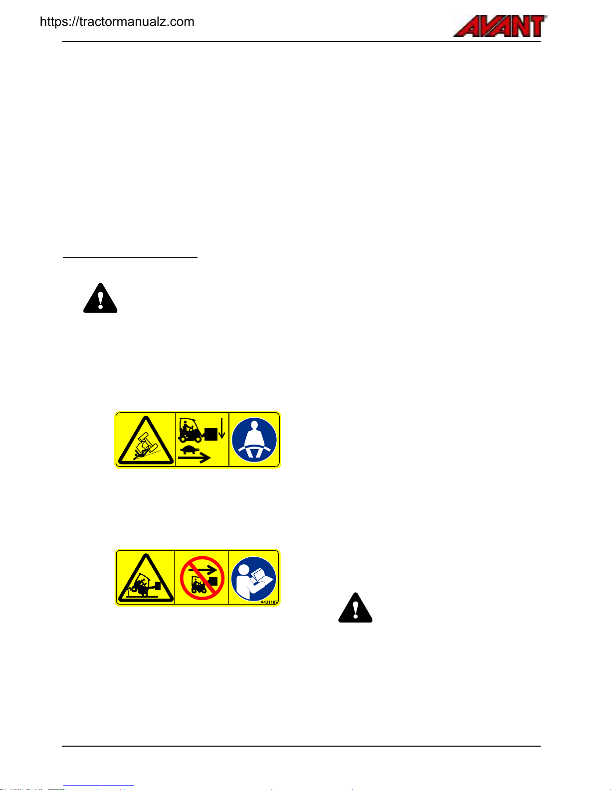
Avant e5
50
.
Material handling
Make sure to use correct type of attachment for each
handled material. Use correct size and type of bucket
for general loose material handling, and pallet forks
for handling pallet loads. Read the manual of the
attachment, e.g. manual of the bucket, for further
information for safe and correct use. Observe the lift
capacity rating of the loader when planning material
handling operations.
The loader is not intended for lifting operations;
never put slings, chains, or ropes on the loader
boom.
Handling of heavy loads
WARNING
Carrying heavy loads can shift the
centre of gravity of the loader and
lead to tipping over of the loader.
Always transport the load as low
and close to the machine as
possible to keep the centre of
gravity low and for the best
stability.
WARNING: Risk of rolling over - Keep loads
close to ground, drive slow when carrying
load.
Always use seat belt.
WARNING: Risk of tipping over (front
direction) - Keep load close to ground, drive
slowly.
Read operator's manual carefully.
Whenever you handle heavy loads or heavy
attachments:
Handle heavy loads only on firm, level ground,
while you drive slowly with the machine.
Uneven or inclined terrain significantly
reduces the safe working load, (see also
page 27).
Use the maximum loads indicated in the
diagram in this manual as a guideline.
All rated operating capacities are based on
the criteria of the machine is level on a firm
supporting ground. When the machine is
operated in conditions that deviate from
these criteria (e.g. on soft or uneven ground,
on a slope or when subject to slide loads),
you must take these conditions into account.
Remember that the actual load carrying
capacity varies greatly according to operating
conditions and control manner.
Keep the articulated frame of the loader in
straight position when you lift heavy loads. If you
turn the loader during load handling, the stability
of the loader will decrease and it may overturn
the machine.
The use of extra rear weights or ballasted tyres
is recommended. See page 40 for different
options.
Make sure to follow the recommended tyre
pressures.
Pay attention that a heavy load or long distance
between the loader and the centre of gravity of
the load will affect the balance and handling of
the loader.
When estimating the lifting capacity of the loader,
remember to take the weight of the attachment
into account.
WARNING
Loader can tip over when you
leave the driver's seat. Always put
the load down on the ground
before leaving the driver's seat.
Follow safe stopping procedure on
page 45.
https://tractormanualz.com

Avant e5
51
How to estimate actual lifting capacity
The actual tipping load and stability of the loader depends on many factors that you must consider when you
handle heavy loads or attachments. Listed in the table below are many factors that influence the stability of the
loader.
Always keep in mind the conditions listed in the following table.
Influencing factor
How you should take it into account
Position of the loader boom
and telescope
Keep load as close to the ground as possible while you drive. Lift only when
ready to unload the bucket or attachment
See load chart and ROC table to estimate the lift capacity of the loader on
level ground. Reduce the indicated maximum load by always taking the
local operating conditions into account
The total load on the loader
boom
Estimate the combined weight of an empty attachment and load
Load chart is based on weight of pallet forks (90 kg)
If the attachment you use is heavier, subtract its weight from the listed
tipping load accordingly
See the operator's manual of each attachment for attachment weight and
possible information about permitted loads.
The distance of the load
from the front tyres
The further away the load is from the loader, the less stable the loader is
Keep the load as close to the ground and the loader as possible
Never drive while load is lifted more than just off the ground
Straight or articulated
position of the loader frame
If you turn the articulated frame, the loader will tip over more easily
Keep the loader in straight position when lifting heavy loads
Levelness of the ground
All listed values are applicable only on level, even ground
Drive slowly on uneven ground
Keep load close to ground and as close to the loader as possible
Installed counterweights
If counterweights are installed, the loader stability is better
Keep standard counterweights fitted
Consider the use of additional counterweights or ballasted tyres for
additional stability
Driver presence
Driver acts as additional counterweight
Load chart is calculated with a 75 kg driver present on driver's seat
If you leave the driver's seat, loader can tip forward.
Movements of the loader
and the load
Lifting of the maximum load is possible only when loader is not moving
Operate the controls of the loader slowly and in a smooth manner.
Dynamic loads can cause loader to tip over
Secure load on the attachment. If load moves or swings, the loader can tip
over
Use correct type of attachment for each type of load
Never lift swinging loads
https://tractormanualz.com

Avant e5
52
In case the machine tips over
Avoid tipping over of the loader with careful operation
and the instructions given throughout this manual.
However, it is important to know what to do in case
the machine tips over.
WARNING
Stay within the space protected by
the ROPS safety frame. Always
keep seat belt on to stay on
driver's seat and to avoid getting
crushed between ground and a
loader that tips over.
In case the loader tips over
Switch off the loader immediately.
Running electric motors and pumps of
an overturned loader will get
damaged quickly and will spill
hydraulic oil.
As soon as possible, lift the loader
back on its wheels to prevent spilling
of hydraulic oil and battery electrolyte.
The loader can in many cases be
lifted back on its wheels by having a
few persons to lift from the ROPS
frame.
https://tractormanualz.com
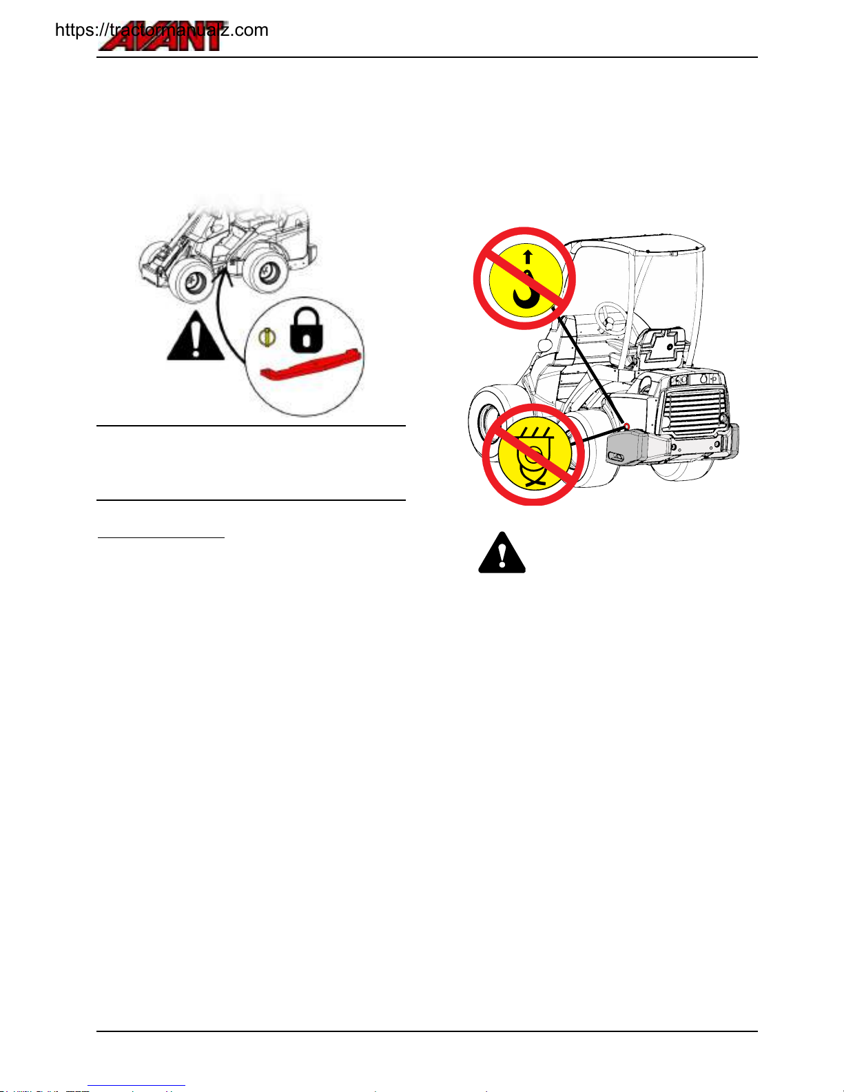
Avant e5
53
.
Transport instructions and tie down points
Before transporting or lifting mount the articulation
frame lock, see page 72. Lower the boom down
and disconnect battery.
Always lock the frame lock before transporting or
lifting the loader. Also remember to remove the
frame lock and test the steering of the loader after
transport.
Tie down points
The loader must be tied down securely if transporting
on a trailer. All four tie down points must be used. If
an attachment is fitted, also t must be tied down.
As standard, there are 4 tie down points:
Two on the front frame, close to the boom
Two on the rear frame, near rear counterweight
To prepare the loader for transport, do the
following:
Always secure the load. Make sure all equipment
is secured also before just a short transport.
Always use straps or chains that are in good
condition and rated for use as load securing
device. Check all hooks and locks.
Consider weight distribution on a trailer.
Sometimes it might be appropriate to load the
loader on trailer rear end first.
Always make sure the trailer is balanced when
loaded in sideways and front/rear directions.
Trailer must never cause upward force on the
trailer coupling of the towing vehicle.
Lock the articulated frame lock.
Lower boom completely down.
It may be necessary to tie down attachments
separately.
Make sure all panels are locked in place.
Remove ignition key and any loose material that
could come off while transport.
DANGER
Risk of moving or falling of the
loader - Never lift or tie down
loader from side
counterweights. Eyelets on extra
side counterweights are for
installing or removing the side
counterweight only. Never attempt
to lift the loader from the
counterweights or use them as
tie-down points.
https://tractormanualz.com
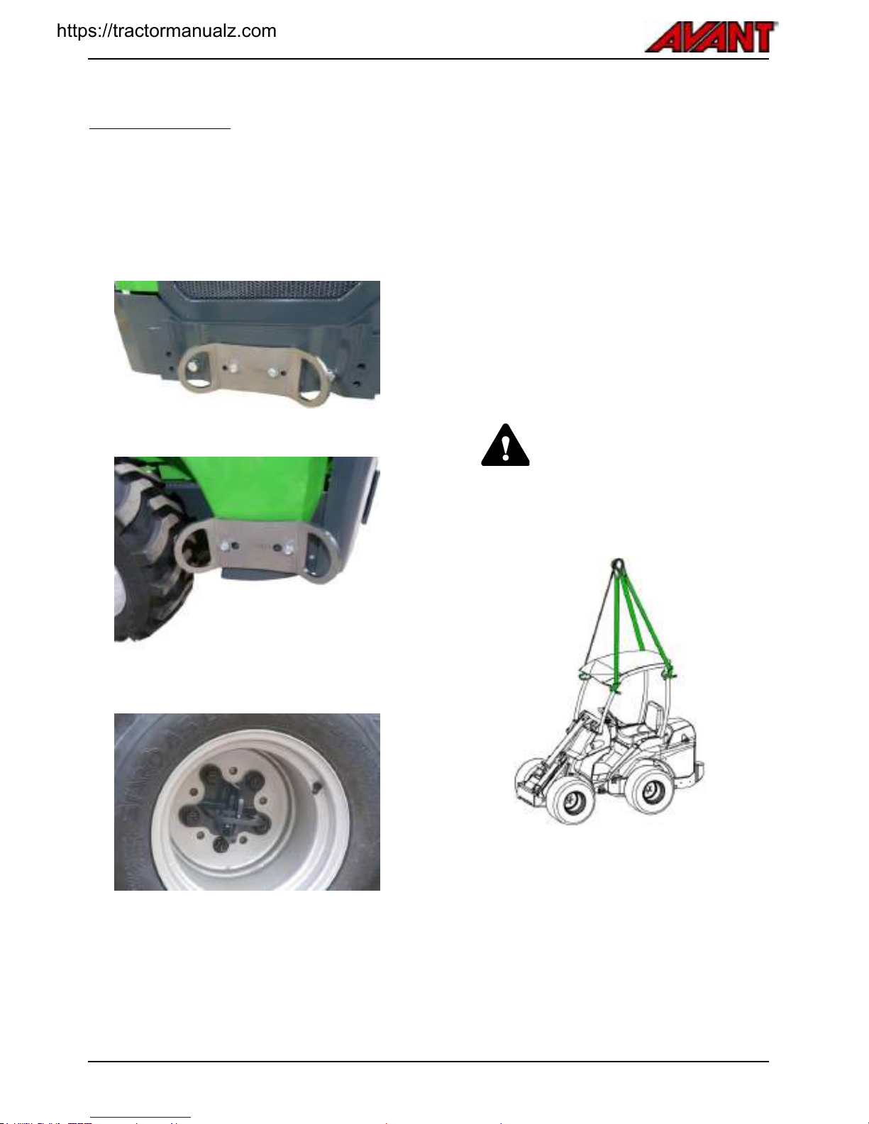
Avant e5
54
.
Tie down options
Optional equipment for frequent trailer transport
If transporting the loader frequently on a trailer,
optional tie down brackets are available for easier
securing of load.
Tie down bracket A418623 installed at the rear
bumper or counterweight
Tie down bracket A418623 installed at the side of
rear frame
For side installation, two brackets are needed.
Tie down bracket on wheel hub A421206
.
Lifting
The loader can be lifted by mounting appropriate
lifting slings on the ROPS frame. Lifting kit A418706
includes all necessary parts to lift the loader, contact
your dealer.
Before lifting, heavy attachment and possible extra
weights must be removed. Mount the frame lock on
the machine.
Make sure that the lifting slings cannot move and
that the machine doesn't swing during lifting. Loop
the lifting straps around all four ROPS posts and
make sure they are not tied or get damaged by e.g.
sharp corners. Follow the instructions given in the
operator’s manual of the lifting slings. To lift a loader
that is equipped with the Cab L, the front, side, and
rear window panels must be removed first.
WARNING
Lower the boom and mount the
articulation frame lock, see page
72. Remove any heavy attachment
and extra counterweights before
lifting. Never lift a loader with
persons riding the machine.
https://tractormanualz.com

Avant e5
55
.
Towing (retrieval of the machine)
The hydrostatic drive system of the loader makes it
impossible to tow the loader in other cases than
moving the loader for a short distance. It is not
possible to release the hydraulic parking brake or the
drive circuit.
If necessary, the loader can be towed with a rigid tow
bar. The wheels of the loader will not spin. Tow only
at low speed and short distances.
Storage
If outdoors storage is necessary, protect the machine
with the designated weather cover (part no. 65436).
Do not use the full, closed
transport and weather cover over
long periods of time as it promotes
corrosion due to moisture that will
condense inside it. The light
weather cover can be used.
Storage of electric loader
Charge the battery to full charge
before leaving the loader unused.
Also, add water to battery, as
instructed on page. Discharged
battery can get damaged during
storage.
The battery must be fully charged and water added
before putting the loader to storage. The best place
to store the battery pack is in a dry, frost-free place.
The battery does not need to be removed or
disconnected from the loader for storage. However,
during long storage periods, disconnect the battery
quick coupler from its counterpart on loader.
A monthly recharge is recommended to keep the
battery in optimal condition.
https://tractormanualz.com
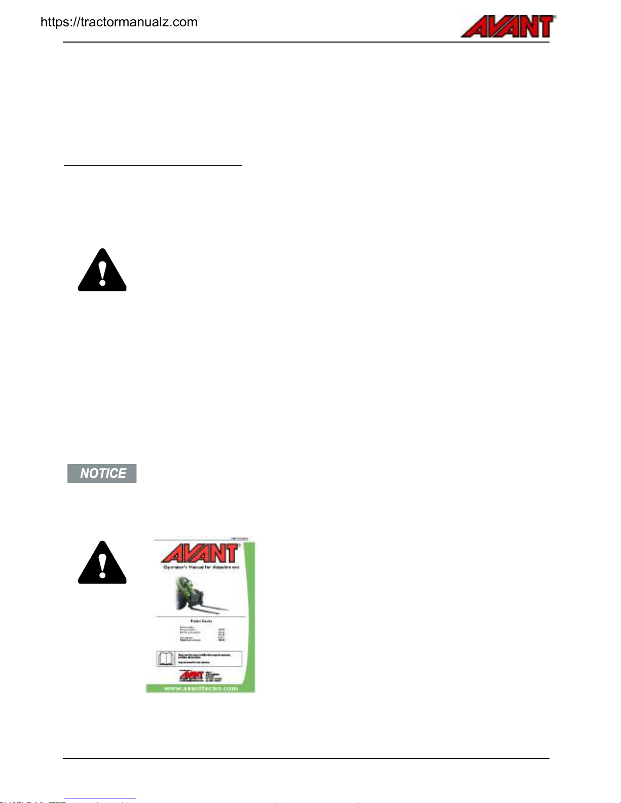
Avant e5
56
Working with attachments
.
..
Requirements for attachments
Any attachment mounted on the loader must meet applicable safety and technical standards and requirements. An
attachment that is not specifically designed for the loader may cause unsafe operation; make sure that Avant e5 is
specifically listed in the operator's manual of the attachment. Some attachments may require the use of special
protective guards or personal safety equipment.
Read Operators Manual of the attachment before you begin to use any
attachment.
Make sure that the attachment is compatible with the loader. Contact your Avant
dealer if necessary.
Make sure that the attachment is connected properly on the attachment coupling
plate, and that it is being used in accordance with the instructions in the
Operators Manual. Follow instructions regarding personal protective equipment
and safety distances.
Put the attachment down on the ground and switch off the loader before leaving
driver’s seat. Familiarise yourself with the operation and stopping of the
attachment at a safe place. Follow service instructions.
Check max. allowed hydraulic oil flow for the attachment. Adjust the speed of the
hydraulic pump so that the output flow is suitable for the work and the attachment. See
page 24.
Manuals of attachments
DANGER
Attachments can create significant risks that are not
covered by this Operator's manual of the loader.
Make sure you have all attachments manual available.
Wrong use of an attachment can cause serious injuries or
death.
Each attachment is accompanied by its own respective
Operator’s Manual. The manual will show important
information related to safety, and how to attach, use, and
maintain each attachment correctly.
https://tractormanualz.com
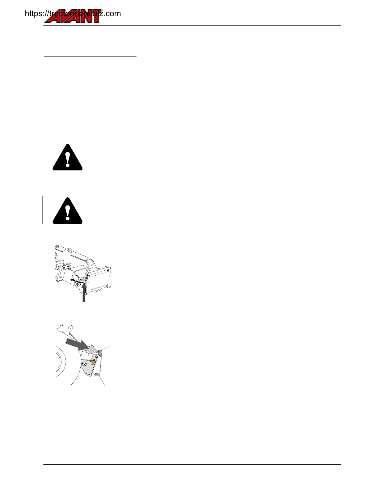
Avant e5
57
.
Coupling the attachments
Attaching the attachment to the loader is quick and easy, but it must be done carefully. If the attachment is not
locked to the loader, it may detach from the loader and cause a hazardous situation. The loader must not be
driven and the boom must never be lifted when the attachment has not been locked. To prevent hazardous
situations, always follow the coupling procedure shown below. Also remember the safety instructions shown in this
manual.
The attachment is mounted to the loader boom by using the quick attach plate on the loader boom and the
counterpart on the attachment. As standard, the attachment is coupled with two manually operated locking pins of
the coupling plate. As an option, hydraulic coupling pins are available, which are controlled with an electric switch.
The following steps show the coupling procedure regardless of the type of coupling types.
DANGER
Make sure that an unlocked attachment will not move or fall over. Do not stay in the area
between the attachment and the loader. Mount the attachment only on level surface.
Never move or lift an attachment that has not been locked.
Always read also the additional instructions for coupling and using of the attachment in
the Operator's Manual of the attachment.
Step 1:
Lift the quick attach plate locking pins up and turn them backwards into the
slot so that they are locked in the upper position.
If your loader is equipped with a hydraulic attachment locking system, see
how to operate the hydraulic locking on the following page.
Ensure that the hydraulic hoses (and the electric harness, if applicable) are
not in the way during installation.
Step 2:
Turn the quick attach plate hydraulically to an obliquely forward position.
Drive the loader onto the attachment. If your loader is equipped with a
telescopic boom, you can utilise this.
Align the upper pins of the loader’s quick coupling plate so that they are
under the corresponding brackets of the attachment.
https://tractormanualz.com

Avant e5
58
Step 3:
Lift the boom slightly – pull the boom control lever backward to raise the
attachment off the ground.
Turn the boom control lever left to turn the bottom section of the quick
attach plate onto the attachment.
Lock the locking pins manually or lock the hydraulic locking.
Always check the locking of both locking pins.
DANGER
Risk of falling objects - Prevent dropping of
attachment
An attachment that has not been completely
locked to the loader may fall on the boom or
towards the operator, or fall under the loader
during driving, causing loss of control of the
loader. Never move or lift an attachment that
has not been locked.
Before moving or lifting the attachment, make
sure that the locking pins are in the lower
position and come through the fasteners on the
attachment on both sides.
Hydraulic attachment coupling
The optional hydraulic attachment coupling plate enables coupling and
disconnecting of the attachment from driver’s seat.
There is a hydraulic cylinder on the attachment coupling plate which moves the
locking pins up and down. The electro-hydraulic system works when the loader
ignition switch is in position ON.
Control switch is located at the control panel on the right (see page ).
DANGER
Risk of falling of attachment - Familiarize yourself with the controls of the loader.
Avoid dropping of the attachment. Operate the hydraulic coupling only when the
attachment is close to the ground.
Always make sure that the locking pins lock properly down in the holes of the attachments
also when using the hydraulic locking. Both pins must be locked.
https://tractormanualz.com

Avant e5
59
.
Coupling adapters
Avant offers coupling adapters to help the use of some specific attachments. See the operator's manual of each
attachment if an adapter can be used.
Both adapter types are locked to the quick coupling plate of the loader. The adapters have similar quick coupling
system to lock the attachment onto the adapter and loader.
Side shift adapter A34893, A37097, or A37166
Side shift adapter is a rigid adapter plate which moves the attachment 40 cm
or 60 cm to the right or to the left side depending on the model. It is intended
for better side reach with attachment that are used on the ground, such as flail
mowers on the side of a road.
Tilt adapter A34148 or A36505
With a tilt adapter the attachment can be tilted sideways, which makes it
possible to:
Make different forms to the ground with a bucket or leveller
Keep pallet fork level when you are driving on surfaces with gradient
Load pallets that are on uneven ground
Level ground on uneven surfaces
The tilt adapter is intended mainly for non-hydraulically operated attachments.
With the optional second auxiliary hydraulics outlet in the front, it is possible to
use hydraulically driven attachments, such as 4 in 1 bucket, pallet fork with
hydraulic side shift, grabbing tool, and artificial turf attachment at the same
time.
All coupling adapters are intended only for specific attachments that can be safely and
efficiently used with an adapter. The adapters are not intended for general use. Any
adapter should be removed from the loader when no longer using an attachment
requiring it.
Avoid the use of bracket adapters that are intended for mounting of 200 series 1
attachments on other loaders. The 200 series 1 attachments are not designed to be used
with other loader models than the 200 series.
CAUTION
Adapter plates reduce lifting capacity - Do not use adapters with heavy loads or
attachments. The adapter plates move the centre of gravity of the attachment further
away from the loader. This increases the risk of tipping over and can limit the use of
heavy attachments.
https://tractormanualz.com

Avant e5
60
CAUTION
Wrong type of attachment, poor attachment locking, or wrong technical characteristics
of coupling brackets can cause hazards that are not taken into account by design of the
loader or the individual attachment. Never use other than original Avant attachments
and brackets. Use of other than original Avant equipment makes it necessary to carry
out detailed engineering to ensure safety, performance, and reliability of the equipment.
Consult your Avant dealer if unsure about the compatibility of equipment with your Avant
loader.
Coupling the hydraulic hoses of the attachment
Hydraulic hoses of the attachment are equipped with the multi connector system, which connects all hoses at the
same time.
WARNING
Never connect or disconnect quick couplings or other hydraulic components while the
control lever of the auxiliary hydraulics control lever is locked on or if the system is
pressurized. Connecting or disconnecting the hydraulic couplings while the system is
pressurized may lead to unintended movements of the attachment, or ejection of
high-pressure fluid, which can cause serious injuries or burns. Follow safe stopping
procedure before disconnecting hydraulics.
Connecting the multi connector system:
1. Align the pins of the attachment connector with corresponding
holes of the loader connector. The multi connector will not
connect if the attachment connector is upside down.
2. Connect and lock the multi connector by turning the lever towards
the loader.
The lever should move easily all the way to its locking position. If the lever does not slide smoothly, check the
alignment and position of the connector and clean the connectors. Also shut down the loader and release the
residual hydraulic pressure.
To disconnect the multi connector system:
Before disconnecting put the attachment down on a solid and even
surface.
1. Switch off the auxiliary hydraulics of the loader.
2. While pushing unlock button, turn the lever to disconnect the
connector.
3. After ending operation put the multi connector on its holder on the
attachment.
https://tractormanualz.com

Avant e5
61
Keep all fittings as clean as possible; use the protective caps on both the attachment and
the loader. Dirt, ice, etc. may make using the fittings significantly more difficult. Never
leave the hoses hanging on the ground; place the couplings onto the holder on the
attachment.
When fitting an attachment, make sure that the hydraulic hoses are not overstretched and
are not in a position where they can be trapped during the operation of the machine and
attachment.
Using the auxiliary hydraulics
Auxiliary hydraulics (hydraulically operated attachments) are controlled with the lever on the control panel, or with
the buttons on the 6-function joystick ( see page 32).
The locking position of the lever facilitates operation of the attachments that require constant oil flow (rotary broom,
backhoe etc.). Make sure to release the lever when not operating an attachment to prevent unnecessary waste of
energy.
DANGER
Risk of serious injuries from moving parts of the attachment - Keep all persons
clear from the danger area of the attachment and loader boom. Going near an
attachment that is in operation can cause a serious risk of injury. Switch off auxiliary
hydraulics before leaving driver’s seat. Operate the controls only when sitting in the
driver’s seat.
The 2-way auxiliary hydraulics control lever ( see page 32) directs hydraulic as follows:
1. Moving towards the locking position will direct hydraulic flow to port
2. This is normally the normal or positive movement of the
attachment.
2. Moving the lever away from the locking position will direct flow in
reverse direction, pressure in port 1.
3. The third port is a free return line to tank, this is required by some
attachments.
4. The 4th port is for the integrated electric socket of the optional
Attachment control switch pack.
On Avant eSeries loaders, the auxiliary hydraulics can be used when:
Driver is seated on the driver's seat
or
External use mode is selected with the Operation mode switch, see page 46.
WARNING
Overspeed of the attachment can cause injuries or dangerous movements of the
attachment. The attachment can break down in a dangerous way, throw objects, or
produce excessive noise and vibrations if operated at too high speed. Never exceed
maximum allowed hydraulic flow of the attachment. Check correct operating flow from the
operator's manuals of the attachment.
https://tractormanualz.com

Avant e5
62
Releasing the residual pressure of hydraulic system
Make sure that there isn't pressure in the hydraulic system that could cause danger during service operations.
To release the pressure in hydraulic system:
1. Lower the boom down completely and place attachment firmly on the ground
2. Switch off the loader
3. Move all control levers, including the control lever of the telescopic boom and auxiliary hydraulics, to extreme
end positions a couple of times
Remember that the boom or attachment can move when releasing the pressure. Move the levers until all
movements have stopped.
Extra auxiliary hydraulics coupling
The extra hydraulics coupling is a double-acting hydraulic with two fittings. Pair of standard type hydraulic quick
couplings are located at the front of the loader, just below the multiconnector.
Before you connect or disconnect standard couplings,
relieve hydraulic pressure as described on page
To connect and disconnect the standard couplings, move
the collar at the end of the female fitting
Note that the protective caps on the loader and the attachment can be fastened to each other
during operation to reduce the accumulation of dirt.
When disconnecting the standard quick couplings a small amount of oil may drip from the
couplings. Wear protective gloves and have some cloth at hand to keep the equipment clean.
To use the extra hydraulics coupling:
1. Activate the extra auxiliary hydraulics outlet:
Switch the selection switch of the hydraulic outlet to position 2. The switch is located on
the control panel on the right side from the driver's seat
2. Use the normal auxiliary hydraulics control lever to control the extra outlet, or use the
buttons of the 6-function joystick
3. When you want to use the multiconnector outlet again, switch the control switch back to
position 1
The quick couplings can be coupled in a way that reverses the function of the control lever. Test the operation
of the attachment after each time it is coupled to the loader.
Keep the couplings clean and use their protective covers.
You can operate either the hydraulic function connected to the standard multiconnector, or the function that is
connected to the extra outlet. Simultaneous use is not possible.
https://tractormanualz.com

Avant e5
63
Battery and Charging
Follow the instructions in this chapter to ensure the full capacity and service life of the battery.
Correct charge cycle, safe area for recharge, water replenishment, and correct operating and charge temperatures
must be taken into account when operating or recharging the loader.
Remove the rear cover to access battery.
Under the cover you can see the following main parts
of the battery pack:
1. Battery pack: 24 2-volt battery cells that are
connected in series.
Connected water refill system with single
quick connector
2. Battery main connector
3. Mains plug for recharge, integrated charger
4. Water level indicator on top of each
individual cell
Leave the rear cover open during
recharge to allow good ventilation
of the battery.
Recharge - General principles
For the best performance of the battery, obey the
following principles:
Charge the battery immediately after using the
loader
When you keep the battery fully charged, you
ensure that the battery pack will retain its
capacity as long as possible. Never store the
loader with an empty battery.
Always charge the battery in a well-ventilated
area.
It is recommended that you remove the panel
covering the battery compartment for the
duration of the charging.
Follow safety instructions. Keep all sources of
ignition away from battery that is being charged.
Do a full charge frequently (charge until the
green charge indicator light is lit)
Never discharge the battery fully. This so called
deep discharge will damage the battery.
Avoid deep discharge of the
battery. Complete discharge can
damage the battery.
Never operate the loader until
there is no power left to drive the
loader.
Charge the battery when the
battery level indicator shows that
no more than 10% of charge is left.
Battery will wear out quickly in
repeated deep discharge cycle
use. Recharge fully discharged
battery with complete charge cycle
as soon as possible.
It is recommended to charge the
battery, when its charge is dropped
to about 20% to 30% level.
If you feel that machine starts to
lose power even the battery
indicator shows plenty of charge
left, charge the battery
immediately.
https://tractormanualz.com

Avant e5
64
.
Battery life
The actual work times will vary greatly, depending on
several factors. The following have high influence on
battery duration:
work cycle, accelerations and frequent stopping
level of carried or lifted loads
use of rotating attachments
ambient temperatures
Condition of battery and correct use and charge
Light to
moderate use
Heavy use
Use time
Using attachments that have a hydraulic motor and
require constant, high flow and power of hydraulic oil,
will use the energy of the battery quickly.
Attachments that are used only short periods of time
are best suited for the e5 loader.
A new battery pack will reach its maximum capacity
only after a few recharge cycles. Battery pack will
slowly degrade towards the end of its useful life.
Extreme conditions can shorten the battery life.
Discharged battery can get frozen, which could
permanently destroy the battery.
.
To keep the battery in good condition
To preserve the current draw capacity of the battery,
observe the following rules regarding charge level.
Always charge the loader immediately after use.
After heavy load or high ambient temperature,
allow the loader and its battery to cool before
recharge.
It is recommended to charge the battery as soon
as the charge level is dropped to 20-30%
Always charge the battery immediately when the
charge level is dropped to 10%. Discharge below
this level should be avoided, as deep discharge
will wear down the battery.
Never discharge the battery fully to a point
where there is no energy left to drive the
loader. Battery might get damaged and will
no longer charge to full capacity.
After each charge, check the battery water level
and if water must be added. Operating with too
low water level will damage the battery quickly.
https://tractormanualz.com
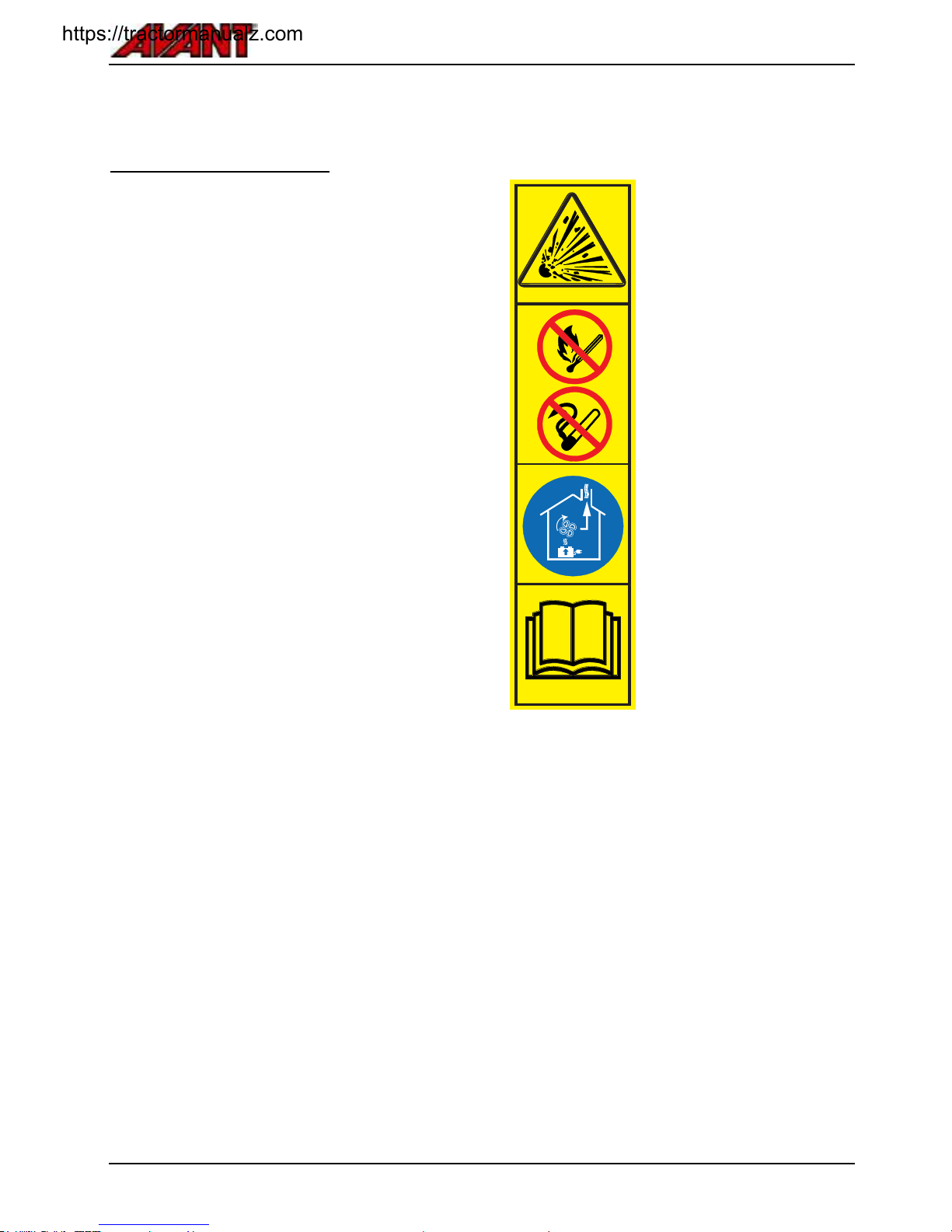
Avant e5
65
.
Charging the battery
Preparation for charging
In preparation for charging, do the following:
Choose a well ventilated place, where you can
leave the loader safely for charging. Do not
recharge in direct sunlight or rain.
When charging, proper provisions must be made
for venting of the charging gases
Open the rear cover of the loader to allow good
ventilation
Leave all vent plugs, tubes, and covers of the
battery itself installed
If the battery is extremely hot, allow to cool
before recharge
Also read the safety information regarding the
battery and electric systems on page 14
Charging site
Charge the loader in shade. In direct sunlight the
battery may overheat during recharge.
Choose a well ventilated place, where you can leave
the loader safely for recharge. When charging,
proper provision must be made for venting of the
charging gases. Never recharge in a closed building
without good ventilation.
Charge after loader is allowed to cool
During recharge the temperature of the electrolyte
rises by about 10°C, so begin to charge the loader
only if the electrolyte temperature is below 45°C.
The loader is equipped with a cooling fan that is
intended to cool the battery and electric components
inside the loader. The fan is activated automatically
when the temperature of the inverter, electric motors,
or the battery has risen above a determined level.
WARNING
Battery produces explosive
gas during recharge - Make
sure to charge only on well
ventilated area.
Make sure that
ventilation is sufficient
when charging the
battery.
Never charge the
loader in a small
garage or shed where
there is no ventilation.
Keep arcs, sparks,
flames, and lighted
tobacco away from
battery.
Never charge damaged
or frozen battery.
See detailed
instructions about
charge process starting
from page 63.
https://tractormanualz.com

Avant e5
66
.
Charger
You can recharge the battery at any point regardless
of the remaining energy left. Whenever possible,
recharge immediately after use.
An integrated charger is standard equipment for all
e5 loaders. Battery is fully charged and all cycles
completed when the green charge indicator light is lit.
The output current and voltage are controlled by the
internal charger and the charge process is
automated.
It is recommended to use only the integrated charger
of the loader to charge the battery. The charge r
output voltage and current are automatically adjusted
during different phases of charge process. If you use
an external charger, the charge voltage and current
may be wrong for each phase of the charge, causing
overheat or boiling of the battery, or damage to
battery cells.
Charge times
Charge times shown here
are typical times in normal
operating temperatures
and with a battery that is in
good condition.
If the battery has been
completely discharged,
allow the charger to
remain plugged for longer
period of time to complete
also the equalising charge
phase.
Charge process
The status and phase of charge process is shown
with the signal lamps on the dashboard, see page
31.
In case the red charge status lamp lights, the battery
is not charging due to several possible reasons.
In addition to the charge signal lamps on the
dashboard, there are identical signal lamps on
charger itself. In case of trouble with charging, and
signal lamps on dashboard do not turn on, see the
lamps on the charger. To see these lamps, remove
the cover below the seat frame.
Equalising charge
During the end of normal charge cycle, the slight
differences of individual cells are balanced. The final
phase of the charge cycle, called equalising charge,
is completed when the green charge indicator light is
lit.
For optimal performance of the battery, it is
recommended to leave the charger mains plug
connected until the battery is completely full. This full
charge process must be made at least every 3 to 5
discharge cycles. The equalising charge is a slower
charge process, but important for the performance of
the battery.
Frequent equalising charges are
vital for the life of the battery and
to maintain its capacity. Full
charge is especially necessary
after a deep discharge or
repeated incomplete recharges.
Equalising charges are carried
out following normal charging
cycle, until the green indicator
light on the dashboard is lit.
Charger plug type
The standard plug type to connect the loader to
electric outlet is grounded CEE 7/7, commonly
known in Europe as "Schuko" type. If you use the
loader in areas where different kind of plug is
needed, your local Avant dealer will give you any
needed additional information. Regardless of the
type of the plug, other instructions in this chapter
apply to all electric Avant loaders.
The charger must be connected to electric outlet with
correct voltage and current output: Charge only from
a grounded electric socket, which is also protected
with a fully functional residual current protection
switch.
Voltage
Frequency
Required current
(fuse)
220-240 V
50-60 Hz
10 A (minimum)
16 A (recommended)
If using plug adapters, use only high quality versions
that are rated for outdoor use and that have also the
grounding wire connected.
Keep extension cables as short as possible. Use
good quality cables that have adequate cable
cross-section for the required current.
https://tractormanualz.com

Avant e5
67
CAUTION
Risk of cable overheat and fire Avoid using extension cables.
Long or thin extension cables can
heat significantly during charging
and melt, causing risk of electric
shock or fire. Avoid using
extension cables. If necessary, use
only as short as possible, good
quality cable with large enough
conductor cross-section.
CAUTION
Risk of electric shock or fireAvoid additional plug adapters.
Bad quality adapters can be
inadequately protected against
dust and water. Some can even
leave the pins of the plug exposed,
creating a serious risk of electric
shock. Never use plugs that leave
the grounding wire unconnected.
Contact a local licenced electrician
to replace the plug if necessary.
CAUTION
Risk of battery overheat and fire
- Use only the built-in charger of
the loader to ensure correct
charge cycle. The current and
voltage output are optimized in the
integrated charger to ensure quick
charge and long life of the battery.
Modified or different type of
charger can overheat the battery or
cause sparks, creating fire. Too
high current or voltage will boil the
electrolyte of the battery,
potentially releasing battery acid.
.
Drive while charging
The charging system allows to operate the loader
during charging. Make sure that the cable will not get
entangled or pulled during use of the loader.
Charge time can be long while using the loader at
the same time. At heavy load, the battery can even
discharge, even if charger is connected to mains
outlet.
https://tractormanualz.com
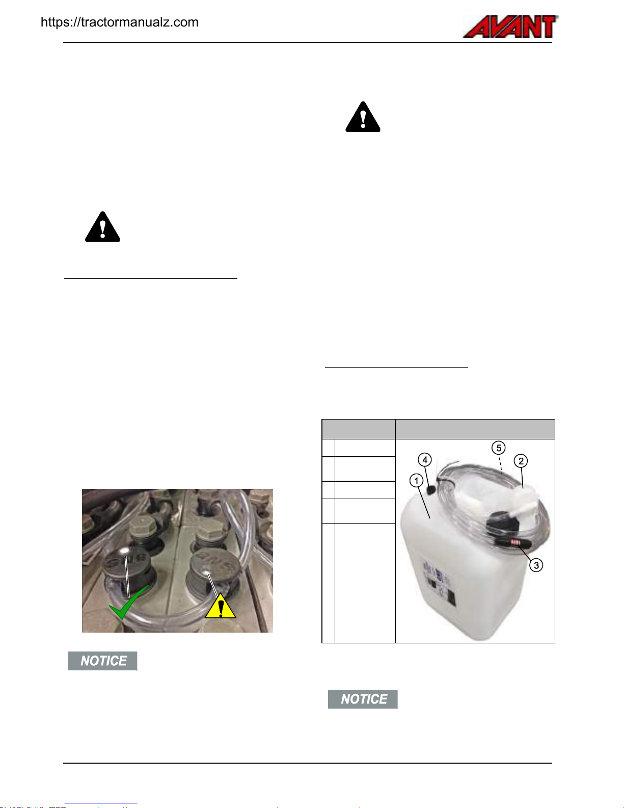
Avant e5
68
.
Battery maintenance - water refill
The battery is a flooded type lead acid battery. Some
of the water of the electrolyte in the battery is
evaporated during charge. To keep the electrolyte
level at sufficient level, additional purified battery
grade water must be added to the battery regularly.
Check the need of water replenishment and add if
necessary after the battery is fully charged.
WARNING
Before you handle the battery, see
safety instructions about handling
the battery on page 14.
Battery water level indicators
To indicate the need for water, on top of each of 24
battery cells there is a float indicator.
If there is sufficiently water in a battery cell, a
white float will be at the top of the check window.
In case the white float is not at the top of the
check window on any of the battery cells, do a
water refill procedure.
In the picture below:
Left side: White float is at the top. If all battery
cells are like this, no water needs to be added.
Right side: Battery water must be added.
Connect watering coupler to add water to the
entire battery.
Always check the electrolyte level
indicators after the battery is fully
charged. Add battery grade water if
any of the float markers is not at
top. Never operate the loader if all
battery cells are not filled properly,
battery may become damaged and
lose some of its capacity.
DANGER
Risk of burns from acid spill Never attempt to remove the
caps of individual battery cells.
Individual battery cells must never
be fully opened. Instead, there is a
quick hatch on top of each cap,
with a place to fit an instrument to
measure the specific gravity of
electrolyte inside cell. To avoid
hazardous spill of acid, the battery
pack must be watered by using the
common, integrated water system,
and test sample of electrolyte must
be taken through the quick
opening.
Battery watering system
A watering system to fill battery pack with water is
supplied with the loader. The watering system
consists of the following parts:
Description
1
Water tank
2
Cap with shut
off valve
3
Flow indicator
4
Tank breather
cap
5
Quick
connector,
connects to
counterpart
on battery
pack
Make sure the watering container
is lifted to at least 2-3 metres
above the top surface of the
battery. This ensures that there is
enough pressure for the water to
flow into all battery cells.
https://tractormanualz.com
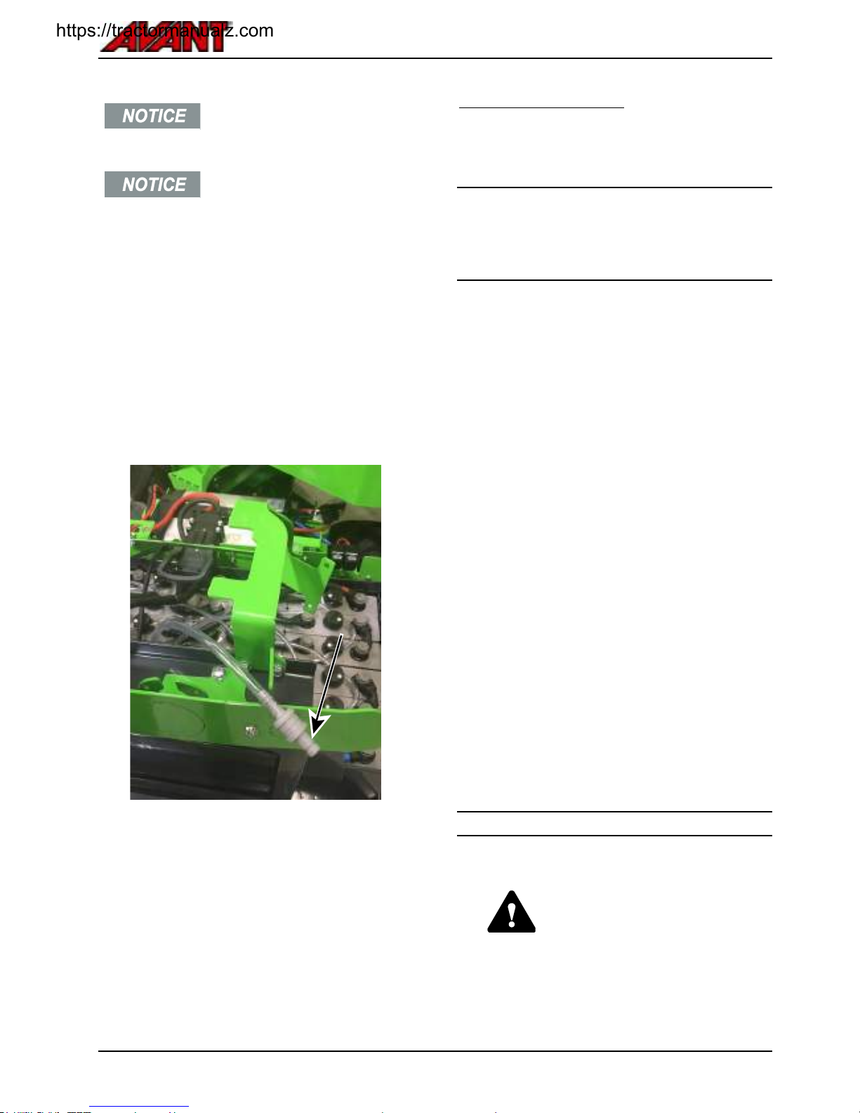
Avant e5
69
To ensure that water is added to all
battery cells, add water while the
loader is on level ground.
Never use tap water or bottled
drinking water to fill batteries.
Use only purified water that is
intended for battery use. Store
water carefully to avoid its
contamination. Tap and even the
purest bottled drinking water
contains minerals and other
impurities that will spoil the battery
quickly.
If you are unsure about the water,
check that the distilled water
complies with standard DIN 43530
part 4 and that the container is
marked accordingly.
Battery watering connector on battery pack
Find the hose and connector for water fill system on
top of the battery. Connect the quick connector of
watering system to this counterpart.
Watering procedure
The battery pack is fitted with watering connector
which allows to add water to all battery cells from a
single point.
The water container must be lifted high enough from
the ground. Recommended height for the water tank
is 2-3 metres higher than the top of the battery
surface. This ensures that the water pressure will be
high enough that all battery cells will be filled.
A breather cap on water container must be opened,
so that water can flow freely.
1. Clean the water hose connectors of the battery
and the watering system.
2. Connect the watering connector to the quick
connector on the battery. Water will start to
flow, and the flow indicator on the hose will
spin.
Use only purified battery water. Even the
cleanest drinking water contains enough
dissolved minerals and impurities to damage
the battery.
3. When the indicator stops, the battery is fully
watered.
Watering may take up to 5 minutes to complete.
Watering system in freezing temperatures
If you store the loader in a cold place, where ambient
temperature drops below 0ºC, the water of the
watering system can freeze. In case the watering
system gets frozen, take the loader to a warm place
and allow the system to melt. Freezing of the
watering system will not cause additional damage.
For the best current capacity, it is recommended to
use and store the loader in temperatures between
+10ºC and +30ºC.
Never add any additives to battery.
Risk of acid spill - Add only pure battery water
WARNING
Never add battery acid to the
battery. Only water is evaporated
during charge cycles. Addition of
any other substance than water
can react chemically and spill
corrosive acid.
https://tractormanualz.com
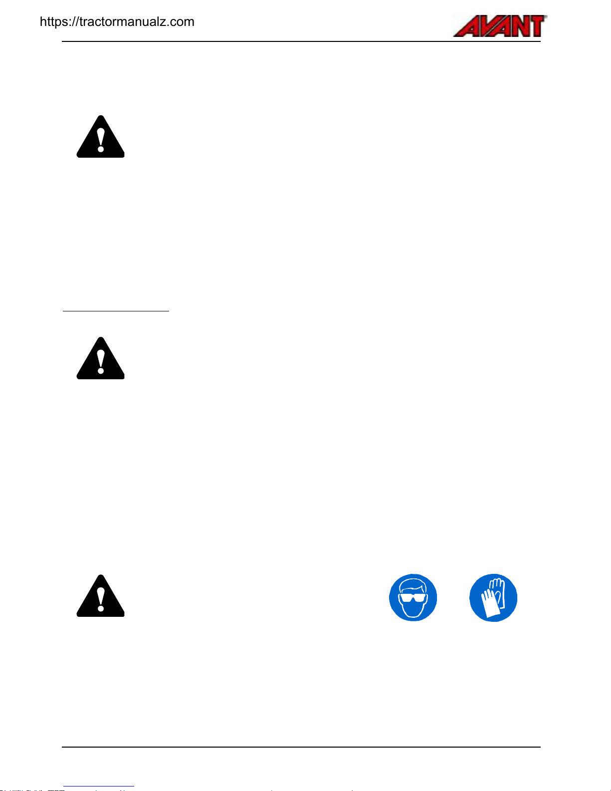
Avant e5
70
Service and maintenance
DANGER
Risk of personal injuries - If the loader is damaged or poorly maintained it can
cause or increase risks of unsafe operation.
To ensure long service life it is important to maintain the loader in good condition. The
maintenance procedures listed in this chapter can be performed by trained or otherwise
experienced operators. If you are not sure about how to do any service operation, ask for
additional information before you start any service or maintenance work.
If the maintenance schedule is not followed, and services made are not marked in the
table in this manual, the warranty may not cover for damages of the loader.
Service parts are available through your Avant dealer or authorised service. Contact your
local Avant service or dealer for any questions or information.
Safety instructions
Switch off the loader and let it cool down before starting any service operation.
Put the service support on the boom lift cylinder when working under the boom. Keep
boom lowered otherwise.
Install the frame lock when lifting the machine, and, for instance, when changing
tyres.
Before working on the electric system or battery, disconnect the battery.
Check hydraulic hoses for cracks and wear. Follow the wear of the hoses and stop
operation if the outer layer of any hose has worn out. If there are signs of oil leakage,
put a piece of cardboard under the probable leakage place in order to find the
leakage. Never use hands to search for leaks, read instructions in this manual about
safe handling of hydraulic components. If you find a fault, the hose or the component
must be replaced.
Contact your Avant dealer or service for spare parts.
.
..
WARNING
Risk of burns, cuts, and sprayed oil or dirt Use Safety goggles and gloves during all
maintenance operations. Always wear protective
gloves, safety goggles and protective clothing. Hot
surfaces and sharp edges can cause injuries. Also
general skin contact with oil and grease can be
harmful, wash hands thoroughly after contact with
oil.
https://tractormanualz.com
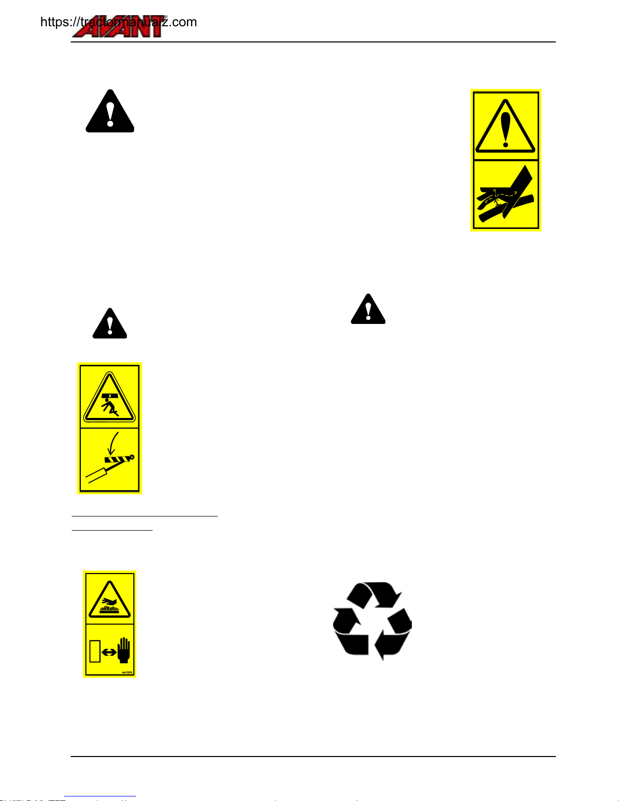
Avant e5
71
.
DANGER
High-pressure ejection of fluid may penetrate skin and cause
serious injuries. - Never handle pressurised components.
Before handling hydraulic components, make sure that the hydraulic
system of the attachment and the loader are completely
depressurised. Do not hold your hand near a fitting when tightening or
opening it, and never use hands to search for leaks. If a leak is
suspected, set a piece of cardboard to detect a leak.
Seek medical attention immediately in case hydraulic fluid is injected
through the skin. Also skin contact with the oil can be harmful, wash
hands thoroughly after contact with oil.
Falling of load - Risk of crushing
WARNING
Always secure the loader boom
with the provided service support,
before going under the loader
boom. Remove any load and
attachments from the loader before
service or maintenance.
Access to electric motor
compartment
WARNING
Risk of burns - Allow loader to
cool before opening covers.
Electric and hydraulic parts may be
extremely hot after use.
The adjacent warning label is
located visibly below the rear
cover. Hot areas include the
hydraulic components and hoses,
and surfaces of electric motors and
inverters.
WARNING
Risk of injury from injected
hydraulic oil and burns - Never
operate loader or attachments if
there are hydraulic leaks. Check
hydraulic hoses and components
only when the loader is safely
stopped and hydraulic pressure is
released. Repair all leaks as soon
as you have noticed them,
because a small leak can quickly
change into a big one. Leaking
hydraulic fluid can cause serious
personal injuries and is also
harmful to the environment.
Consider the environment
The fluids in the machine are
harmful to the environment.
Never allow fluids to leak in the
environment.
Take waste oil and fluids to
recycling station. Find out about
your local requirements
concerning the recycling or
disposal of other components.
https://tractormanualz.com

Avant e5
72
.
Installing of service support and frame
lock
Installing boom service support:
The red service support of the boom lift cylinder is
located at the tip of the boom, behind the attachment
coupling plate.
Make sure that the boom stays up during
maintenance operations by putting the service
support on the lift cylinder piston rod. Secure the
service support by locking it on the piston rod with
the long screw that is on the support.
Service support stored at the tip of the boom
Service support in place
Frame lock:
A red frame lock bar is stored under the operator's
cab.
This lock bar is intended to lock the articulated frame
to make the loader frame stay straight during e.g.
lifting or transportation.
The holes for the frame lock bar are on the left side
of the loader, below the access step.
1. Slide the hook type end of the bar through a
hole on the rear frame of the loader.
2. Turn the bar towards the front hole. The other
end should remain locked in the hole on the
rear frame.
3. Align the holed end of the bar and the frames
by turning the steering wheel. This can be
done without starting the loader.
4. Once aligned, slide the bar and lock with its
cotter pin.
https://tractormanualz.com

Avant e5
73
.
Daily inspections
Do a walk-around check of the loader before each working shift. Check at least the following points. Do not use the
loader if you notice problems with any of the listed items.
Check before start
To check
1
Tyres: pressure and
condition
Check visually daily. Do not use if there is visible damage on tyres.
Check with pressure gauge if wrong pressure is suspected, see page 73
2
Level of hydraulic oil
Check level of hydraulic oil especially after using a new attachment that
drains hydraulic oil from the loader as the hydraulic system of the attachment
fills up. Check also after repairing a leak.
3
Need for lubrication
Make sure all joints are lubricated sufficiently, see page 76
4
Cleanliness of electric motor
compartment and radiators
Keep inner compartment of the loader clean to prevent electric motors and
systems from overheating
Check and clean external surfaces of electric motors, inverters, and charger.
Use damp cloth for cleaning
Dust, hay, and other dry materials inside the inner compartment will cause a
fire hazard
5
Clean and check the battery
Keep the top surface of the battery clean
Check the battery cables, connectors, and terminals visually. If a cable or its
insulation has become brittle, there is a risk of short-circuit. Replace cables
and insulators as necessary
In case of any trouble, or if you need more information, contact your Avant
dealer
6
Oil or other leakages
Check the underside of the loader. Also check ground/floor surface for signs
of leakage
Never operate if leakage is observed. Repair before use
7
General condition of the
loader
Check for damages on metal parts or rust
Ensure all safety decals are in place and legible
8
Condition of the safety
frame, seat belt, lamps, and
other safety equipment
Safety frame (ROPS) and protective roof (FOPS) must be fitted
Safety structures must not have visible damage or deformations. They must
be replaced after any incident
Make sure all lamps are functional and clean
9
Attachment and its locking
Check the locking of attachment and locking pins on attachment coupling
plate
Function of attachment, position of attachment hoses
See also the operator's manual of the attachment, see page 4
https://tractormanualz.com

Avant e5
74
Check after starting the loader
11
Drive control and steering
Check operation of pedals and steering after start. Pedals must move freely
and not get stuck or feel stiff
Check that loader stops when not pressing the drive pedals. Do not use the
loader if braking performance is decreased or if the loader creeps
Allow the loader to warm up and check steering
12
Boom movements
Boom should move smoothly to all extreme positions when using without an
attachment
If attachment is fitted, check that the boom moves smoothly within its normal
operating range
Hydraulic hoses or electric cables must not get pinched or stretched in any
position of the boom
https://tractormanualz.com

Avant e5
75
.
Maintenance schedule
Following tables show the maintenance and service points and intervals of the loader. There are more detailed
instructions about each service operation, in numerical order, on the following pages.
Part A - Loader
Every week
After first 50 h
Every 400h /
year
1
Clean the machine
●
■
■
2
Grease the greasing points
● ● ●
3
Check tyre pressure
●
4
Check tightness of bolts, nuts and hydraulic fittings
■
●
●
5
Check hydraulic oil level
●
6
Change hydraulic oil filters
●
●
7
Change hydraulic oil
●
●
8
Clean cooling fans and surfaces
■1
●
●
9
Adjust or replace the slide pads of telescopic boom
●2
■3
●4
10
Check pressure of hydraulic system
●
●
11
Adjust pressure of hydraulic system
■
■
1.
Depending on operating conditions. Daily check may be needed
2.
Check slide pads 1 to 4 on the boom
3.
Adjust or replace slide pads 1 and 2
4.
Check all slide pads and replace if necessary
●
Maintenance operation
■
When necessary
.
..
Part B - Battery
Daily
Every week
Every month
Every 400 h /
year
1
Recharge battery
●
2
Refill battery water level
■
●
3
Ensure full charge
●
4
Clean battery
■*
●
5
Check battery visually
Check all cables and
insulators
● ● ●
6
Check battery capacity and
all individual cells
●
https://tractormanualz.com

Avant e5
76
.
Loader maintenance
1. Cleaning of the machine
Cleanliness of the loader is not only a question of
outer appearance. All surfaces, painted and others,
will stay in better condition when they are cleaned
regularly. A dirty machine will run hotter and can
cause poor performance, shorter battery life, or
stopping of loader to overheat.
Pay special attention to the cleanliness of the
battery, electric motors, inverters, charger, the
hydraulic pump compartment, hydraulic quick
couplings and the oil tank cover.
The outer surfaces of the loader can be carefully
washed with a pressure washer. Never use pressure
washer to clean the inner parts of the loader or the
battery, electric parts may become damaged. Also,
wash the hydraulic components (hoses, cylinders),
any electric component, decals, and the radiators
carefully, never with high pressure washer.
There is a service hatch on the loader to help with
the cleaning of the rear frame. Reinstall the cover
plate after cleaning to protect the internal
components of the loader.
Clean cab interior with appropriate mild detergent
and cleaning supplies.
After washing grease all greasing points.
The loader is equipped with a
hydraulic oil cooler, which is located
at the right side of the loader, near the
controls of the loader. Make sure to
clean the oil cooler cell with
compressed air every time you are
servicing the loader - and even more
frequently if the loader is being used
in dusty conditions.
Never spray the battery or electric
motor compartment with a
pressure washer. Battery and
electric connectors and insulators
may get damaged. Use cool or
warm water to use other parts of
the loader, never use hot water
(above 70ºC).
2. Greasing of the machine
Greasing of pivot points is very important to avoid
wear. Most of the greasing points are on the loader
boom. The following table and pictures show the
location of grease nipples.
Suitable lubrication interval depends heavily on
operating conditions. The need for lubrication must
be checked at least after every 10 hours of use. Add
grease if the joints have become dirty. Adequate
lubrication of the joints must be ensured. Lack of
lubrication will cause the joints to wear quickly.
Use general purpose machine grease. A grease gun
is needed to apply grease to grease nipples. All
lubrication nipples are standard R1/8" nipples.
Replace any damaged nipples.
Clean the end of the nipple before greasing and add
only a small amount of grease at a time. New
lubricant will push out dirt from joints. Wipe excess
grease with a cloth.
Greasing points are listed in the following table.
Reference
Number of points
A
1.
Articulation joint
Left side of loader
2
2.
Steering cylinder
Both ends of steering cylinder, near
articulation joint
2
B
3.
Boom pivot pin
Both ends of boom pivot
2
4.
Lift cylinder
2
5.
Levelling cylinder
If fitted. Lower end accessible under front
cover.
2
C
6.
Telescopic boom
Grease when boom is completely
retracted
2
D
7.
Tilt cylinder
2
8.
Attachment coupling plate
Pivot pins and tilting mechanism
5
https://tractormanualz.com

Avant e5
77
A. Articulation joint and steering cylinder
B. Front frame
C. Telescopic boom
D. Coupling plate
3. Tyre pressure check
Check tyre pressure when heavy attachments and
extra counterweights are not attached. Correct tyre
pressure depends on intended load. Refer to
Chapter Technical Specifications.
4. Check and tightening of bolts, nuts
and fittings
Check tightness of bolts, nuts and hydraulic fittings
regularly. However, do not overtighten; tighten
hydraulic fittings only if necessary.
Wheel nuts should be tightened 150 Nm.
Check the tightness of the pivot pin locking screws, if
loose tighten and use thread locker.
Tighten wheel nuts after first 5
operating hours. Check tightness of
wheel nuts regularly.
https://tractormanualz.com

Avant e5
78
.
5. Hydraulic oil level
Hydraulic oil level can be checked with the dipstick in
the filler. Lock the boom with boom service support
to access the filler opening.
Oil level should be approximately at the lower mark
of the dipstick (1) when the loader boom is up.
Tighten the dipstick on its threads for measurement.
Refill when necessary, but never exceed the upper
limit mark (2). Doing so can cause oil to overflow
when lowering the boom.
.
..
1.
Target marker. Fill to this
mark when hydraulic
system is cold.
The area highlighted in
the adjacent figure
shows approximately the
acceptable level.
2.
The second mark on the
dipstick indicates max
level of hydraulic oil. Oil
can reach this level
when hydraulic system
is hot.
Never overfill the
hydraulic oil tank. Oil
can flow over, or foam
inside tank.
.
6. Hydraulic oil change
When changing hydraulic oil, the oil can be removed
with a suction pump from the filler opening, or by
removing the drain plug on the right side of the front
frame, close to the articulation joint. In both cases it
is important to clean the magnetic drain plug.
Hydraulic oil tank capacity is 36 l.
Hydraulic oil type
Always use correct type of clean, high quality ISO
VG-46 certified mineral hydraulic oil. If ambient
temperature is hot, higher viscosity oil may be
required, contact dealer.
In freezing temperatures use oil designed for the
purpose, in order that the machine operates as
intended and starting is easier.
Use of synthetic or bio hydraulic fluids
may cause premature wear or
damage to the hydraulic components
and is not permitted. Using wrong
type of hydraulic oil will void the
warranty.
7. Changing of hydraulic oil filter
The loader is equipped with a hydraulic oil return
filter. It is located on top of the hydraulic tank, next to
the dipstick. Take off the cover and replace the oil
filter cartridge. Dispose used filters as instructed by
your local authorities. Never throw oil filters in
general trash.
Filters - list of filters
Filters for Avant e5
Hydraulic oil return filter
74093
https://tractormanualz.com

Avant e5
79
8. Clean cooling fans and surfaces
There are total of three cooling fans on the loader:
Hydraulic oil cooler
Electric motor compartment and battery cooling
fan
Cooling fan in charger
All of these must be kept clean to ensure reliable
operation and long service life of the loader.
In addition, clean the outer surfaces of the charger,
inverters, and electric motors. Use damp cloth to
wipe them clean. Never clean during recharge to
avoid the possibility of creating sparks.
If operating the loader in dusty conditions, the
cooling fans and surfaces must be cleaned more
frequently.
Proper cooling is essential. To
prevent overheating, clean screens,
cooling fins, and external surfaces of
electric motors, inverters, and the
charger. Avoid spraying water at
wiring harness or any electrical
components.
9. Adjust and replace slide pads of
telescopic boom
The telescopic boom is equipped with replaceable
slide pads. The slide pads are wear parts that wear
during the use of the telescopic function. All slide
pads can be replaced, and the nylon slide pads on
the outer boom can also be adjusted. Adjustment or
replacement of the slide pads is necessary to
compensate for wear and to adjust the play between
the outer and inner telescopic boom.
At the lower end of the outer boom there are
pairs of nylon slide pads 1 and 2, accessible
from around the boom.
In addition, there are pairs of aluminium-bronze
alloy slide pads 3 and 4, at the upper end of the
inner boom. To access pads 3 and 4, the boom
parts must be separated.
Slide pads 1 and 2
Slide pads 1 and 2 can be
adjusted by mounting thin
adjustment sheets between the
boom and the slide pad.
Extend the telescope almost
completely and press the boom
gently against the ground. This
way it is the easiest to mount an
adjustment sheet under lower
slide pad 1.
However, if there is substantial
wear in the slide pads it is
advisable to replace both pads
1.
Slide pads 3 and 4
Slide pads 3 and 4 at the upper
end of the inner boom last long
in normal use. They should be
checked after every 400
operating hours and replaced at
least after 800 hours of use.
To check these slide pads, take
the inner boom completely out
of the outer boom. If the pads
have worn so much that they
are in level with the boom, or
excessive boom play can’t be
removed by adjusting slide
pads 1 and 2, replace all slide
pads.
To replace slide pads 3 and 4 the
boom must be partially
disassembled. Lifting equipment is
required in order to do the service
safely. It is recommended to leave
this service operation to your
nearest Avant service partner.
Slide pad part numbers
Slide pad 1
A48339
Adjustment sheet, long:
A48014
Slide pad 2
A412868
Adjustment sheet, short:
A412971
Slide pad 3
A47922
Spacer under slide pad 3
A47941
Slide pad 4
A48343
https://tractormanualz.com
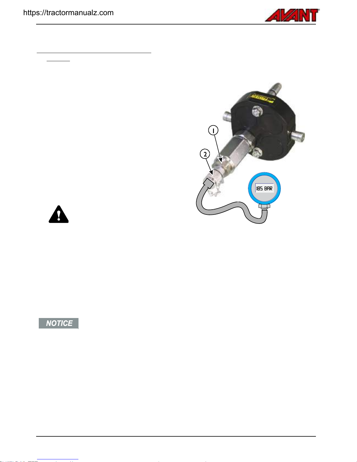
Avant e5
80
.
10. Check pressure of hydraulic
system
Pressure of the boom and auxiliary hydraulics are
measured from the auxiliary hydraulics
multiconnector. It is recommended to leave the
checking operation to qualified service technicians.
At minimum, a hydraulic pressure gauge with
appropriate measurement scale and a measurement
fittings are required. See picture for measurement
set up.
The main pressure relief valve for the auxiliary
hydraulics pump is located on a valve block at the
rear frame of the loader. However, the pressure of
the boom and auxiliary hydraulics is adjusted from
the boom control valve. The main pressure relief
valve must not be adjusted. If boom pressure can't
be adjusted high enough from the boom control
valve, the pump and main relief valve must be
checked. Contact Avant service.
WARNING
Risk of injection of hydraulic oil
- Wrong handling of the
hydraulic system or wrong tools
can cause ejection of hydraulic
oil. It is recommended that
pressures should only be checked
or adjusted by a competent and
experienced technician. Contact
your AVANT dealer if you need
assistance.
Never adjust pressure to higher
level than recommended setting.
The electric drive system is
designed to operate at the
intended pressure level. Other
settings can damage electric drive,
modify the response of the
controls, and decrease battery life.
Warranty will not cover for
damages caused by wrong
pressure setting. Never remove
tamper resistant seals from
pressure relief valves.
Pressure measurement from multiconnector
To connect a pressure gauge, you need at least the
following fittings, shown in the figure:
1. 64743
2. 64194
Boom control valve
There is a pressure relief valve on the control valve
assembly. This is shown in the picture below. Adjust
boom and auxiliary hydraulics from this valve so that
the pressure gauge fitted to auxiliary hydraulics
outlet shows the correct pressure (18,5 MPa (185
bar)).
1. Loosen and remove the locking nut
2. Turn the adjustment screw below it with an
allen key.
Turn only with small increments, max 1/8
rounds at a time.
3. Check pressure after each adjustment.
4. Check pressure once again after tightening the
securing cap nut back.
Never attempt to adjust boom pressure from the
main pressure relief valve located at the rear frame.
Contact service if you suspect that the main pressure
relief valve might be damaged or wrongly adjusted.
https://tractormanualz.com

Avant e5
81
Drive pressure:
Drive pressure needs to be checked only if there is a
clear indication of reduced traction force of the
loader.
Drive pressure check is
recommended only for
experienced service professionals.
Special instruments are required.
To check the pressure in the drive circuit, you need
to install a pressure measurement fittings to the drive
pump valve block. Pressure gauge with a minimum
range of up to 400 bar is needed.
If pressure seems to be clearly wrong, your nearest
service provider can test the operation of two
pressure relief cartridges which have fixed pressure
setting. Also the hydraulic drive motors, drive pump
feed pressure, and brake release pressure should be
checked when investigating drive system related
troubles.
11. Adjust pressure of hydraulic
system
If the pressure check of boom and auxiliary hydraulic
systems indicates that the pressure is wrong, it can
be adjusted only in case the adjustment is not
sealed.
Pressure adjustment screw is locked with a nut,
loosen the nut first. Adjust the pressure incrementally
with an allen key. Turn max. 1/8 rounds at a time and
check pressure again. See pictures for pressure
adjustment points.
DANGER
Never exceed the recommended
hydraulic pressure settings.
Excessive hydraulic pressure may
lead to hydraulic oil ejection by
hose burst or component failure.
Wrong adjustment will damage or
wear the hydraulic pumps,
cylinders, and hydraulic motors.
Warranty does not cover damages
caused by excessive hydraulic
pressure.
Drive pressure:
Cannot be adjusted by user. If the pressures are
clearly wrong, the pressure relief cartridges with fixed
pressure setting must be replaced. Contact service
for correct parts.
https://tractormanualz.com
Avant e5
82
.
Battery maintenance
Battery connector
In addition to the automatic main switch, also
disconnect the battery if the loader will not be used
for a longer period of time, or when servicing the
machine. The battery pack can be disconnected
manually from the loader by disconnecting the main
battery cable.
Pull the connectors apart from each other fully
disconnect battery. Disconnect battery in at least the
following cases:
before you do any maintenance that requires
access near electric motors or other main electric
parts
before maintenance of any electric component
before you disconnect any electric cable
there is a risk of fire
when loader is being transported
there is visible mechanical damage on battery
you plan to store the loader for long storage
period.
1. Recharge daily
Recharge battery after each time loader is used. Also
partially drained battery must be recharged. This
ensures maximum life of the battery.
Check battery water level after each charge cycle
and add water if necessary. See page See page 63
for charge and water instructions.
2. Refill battery water level
After each charge cycle, check the level of electrolyte
in battery cells from the float caps. Add battery water
as described in page See page 63.
3. Ensure full charge
To balance the charge between all individual battery
cells, do a full charge at least weekly. Allow the
charger to be plugged in until the green indicator light
is lit. The balancing charge is made at the end of
charge cycle. It is recommended to do the full charge
as often as possible.
4. Cleaning of battery
The battery should always be kept clean and dry to
prevent so called leakage currents between battery
cells. Any dirt or liquid on the battery can cause
current to flow between battery cells. This will cause
discharge of individual cells and poor overall
performance of the battery pack.
Any liquid on the battery or in the battery tray must
be considered as acid and necessary precautions
must be taken. Wear safety gloves that protect from
contact with acids. Use preferably a suction system
to remove any liquid on battery. Dispose materials
use for cleaning in appropriate manner.
During battery recharge, small quantities of
electrolyte particles escape and form a weakly
conductive layer on the cell covers. Leakage current
flows through this layer then, leading to increased
and varying self-discharging. If suspecting that
battery capacity is weakened after weekend storage,
this dirt can be the cause.
DANGER
Risk of sparks, fire, and
explosion - Dirt on battery can
cause current to flow between
battery cells. Dirty battery can
cause short-circuit of battery cells
and sparks. This can be a source
of ignition for gases produced
during charge. Clean the top of the
battery before recharge. Never
clean during recharge to avoid
sparks caused by static electricity.
WARNING
Risk of battery damage and acid
spill - Never use pressure
washer to clean the battery.
Pressure washer can damage the
battery cells or the caps on top of
the battery, allowing water to enter
battery. This will result in battery
damage, and can also cause
battery electrolyte (acid) to spill
from battery. Clean battery as
instructed in this manual.
https://tractormanualz.com
Avant e5
83
Cleaning procedure
CAUTION
Risk of acid burns - Wear
personal protective equipment
when handling battery. Wear
safety goggles, gloves, and
protective clothing when cleaning
the battery. Electrolyte that has
spilled or evaporated from the
battery can be acid.
The plastic parts of the battery may only be cleaned
with water or water-soaked rags without additives.
After cleaning, the battery surface must be dried by
suitable means, e g with compressed air or cleaning
cloths. Hot air devices with open flame or glow wires
must not be used.
The battery base is sealed and will collect water. If
liquids are on battery drain tray, keep in mind that
any liquid must be extracted by suction, handled as
acid, and disposed of correctly. There are a few
small solid plastic tubes in between the battery cells
to reach the bottom of the battery tray with a suction
device.
Observe the local regulations relating to the use of
water and treatment of waste. Never allow washing
water to drain into the environment.
5. Check battery visually
Check the battery, all cables, and insulators visually
for signs of dirt and mechanical damage. Search for
the following:
Dirt or dust on battery or between battery cells
Dirt around battery and between battery and its
metallic tray
Liquid leakages on battery, between cells, or on
battery tray
All cables, cable insulators, cell caps, electrolyte
level indicators, watering system tubes and
connectors
Dirt that gets between the cells or the battery tray
can cause wear of the battery cells. If battery gets
worn enough, so that insulation from each other or
from external conductive parts can be suspected,
battery must be taken off from service and replaced.
.
6. Battery condition tests
DANGER
Risk of electric shock, sparks,
fire, and explosion of battery Tests listed here are intended
for experienced operators and
service professionals. Use
proper instruments and personal
protective equipment when you do
condition tests.
WARNING
Risk of electric shock, sparks,
and fire - Follow correct
procedure to measure currents.
Never attempt to measure current
by connecting a multimeter or
similar directly between battery
poles. This wrong method can, at
minimum, destroy the metering
device, and also cause sparks, fire,
or electric shock. Know how to
measure electric systems or
contact your local service point.
The output voltage of the battery in unloaded
condition tells only part of the status of the battery.
The individual cells may have become damaged so,
that they output nominal voltage without load, but
voltage drops significantly when current is drawn
from the battery.
If individual cells are damaged, the performance of
the loader can be reduced significantly. Individual
cells of the battery can be replaced by your nearest
authorised Avant or Exide service partner. However,
some basic tests are described here to help with
logging the condition of the battery and with
troubleshoot.
https://tractormanualz.com
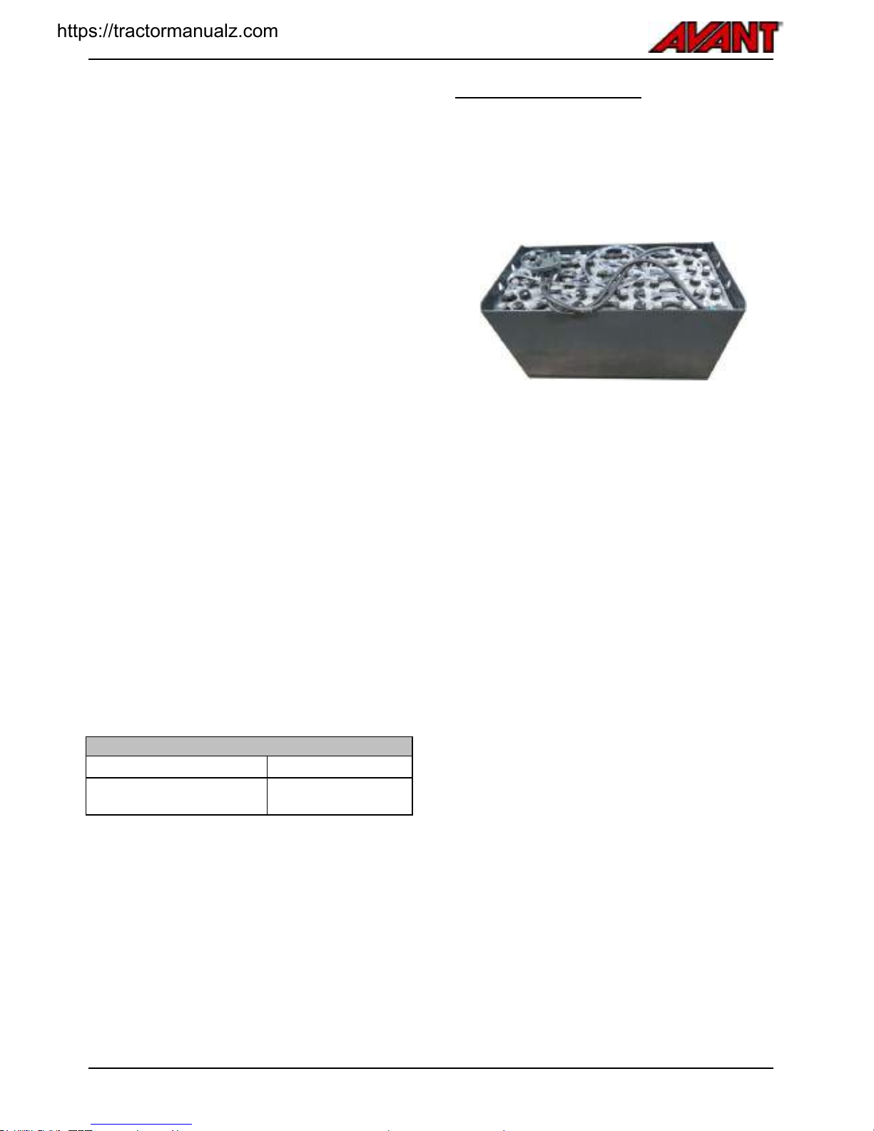
Avant e5
84
.
Insulation resistance test
At least once per year, the insulation resistance of
the loader and the battery must be checked by an
electrical specialist. The tests on the insulation
resistance of the battery must be conducted in
accordance with standard EN 1987-1.
The insulation resistance of the battery thus
determined must not be below 2400Ω (50Ω per Volt
of nominal voltage), in compliance with EN 50272-3.
Test electrolyte condition and record results
After charging has ended the specific gravity and the
temperature of the electrolyte in all cells should be
measured and recorded.
If significant changes from earlier measurements or
differences between the cells or bloc batteries are
found further testing and maintenance are required.
Contact service.
Test of condition of each individual battery cell
Measurement of the output voltage at rest of total
battery pack or individual cells will not give accurate
result of the condition of the battery. For more
accurate results and troubleshoot, measure output
voltage of each cell under load.
To test, operate the loader under heavy load. Lock
auxiliary hydraulics to ON without an attachment at
high motor rpm to apply load.
Use a voltmeter and measure each individual cell.
Write down output voltage of each cell under load
and at idle. Those that have lower voltage output
under load are likely damaged and need further
investigation.
Nominal density of electrolyte*
Fully charged battery
1,29 kg/l
Completely discharged
battery
1,13 kg/l
* Temperature affects measured specific gravity of
electrolyte. Therefore the temperature of electrolyte
at the time of measurement must be recorded.
Correlation factor is -0.0007 kg/l per °C.
1.28 kg/l at 45°C corresponds to a specific gravity of
1.29 kg/l at 30°C
Replacing battery pack
To remove the battery pack from the loader, use
lifting equipment capable of lifting the entire battery
pack. Never remove individual cells of an installed
battery. The battery must be replaced as a complete
assembly. Replacing individual cells without full
analysis of the condition of all battery cells can cause
the new replaced cells to get damaged quickly.
https://tractormanualz.com
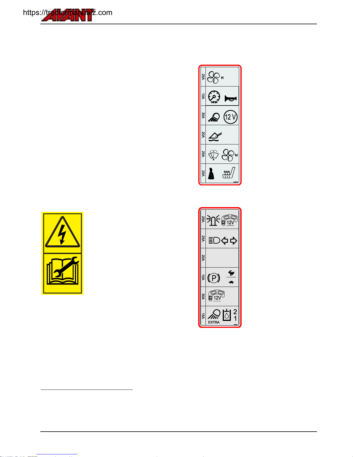
Avant e5
85
.
Electric system & fuses
The e5 loader is equipped with 2 electric systems:
1. The 48 V high current system for electric
motors
This system controlled by the inverters, there
are no separate fuses
2. Regular 12 V electric system for all instruments
and controls
Two fuse boxes at the front of the loader
Main fuse box after 48 V to 12 V DC-DC
converter at rear left of the loader:
10 A fuse before DC-DC converter
7.5 A fuse for the ignition key circuit
In the event of electric malfunction, always check the
two 12 V system fuse boxes first. If a fuse is blown
repeatedly, search for cause of burning fuse. Electric
cables may be damaged. Contact service.
WARNING
Risk of high-current electric
shock, fire, and explosion of
battery - Never repair or modify
the 48 V electric system. Contact
with high-current parts of the
electric system can cause a
potentially lethal electric shock,
regardless of the relatively low
voltage. Contact authorized service
in case of trouble with the electric
drive system.
Main fuse boxes of 12-volt system
There are two fuse boxes located outside the cab, on
the right side of the loader boom.
Lift the boom first for easier access to the fuses, if
possible.
Remember to use the service support. If the boom
cannot be lifted, the fuses can be checked after
removing the right side cover plate.
Hydraulic oil cooler fan fuse
The red indicator on the dashboard indicates blown
hydraulic oil cooler fan fuse. If the indicator is lit,
check the10 A fuse of the oil cooler fan. Check the
cooler fan can rotate freely and is not blocked.
Contact Avant service if necessary.
12 V Fuse box 1
1
Hydraulic oil cooler fan fuse
2
Dashboard, instruments
Signal horn
3
Standard work lights
12 V electric outlet
4
Boom floating
5
Windscreen washer and wiper
Cooling fan for electric system
and battery pack
6
Electric joystick switches
Seat heater
12 V Fuse box 2
1
Warning beacon
Continuous 12 v of attachment
control switch pack
2
Road traffic light kit
3
not in use
4
Parking brake (release)
Drive mode / drive speed
range selection switch
5
Switches of attachment control
switch pack
6
Extra work light kit
Selection switch of hydraulic
flow to extra front or rear
couplings
.
..
Ignition switch fuses
The ignition switch controls the main switch of the
loader by a separate electricity circuit. If the loader
does not respond to ignition switch, even if battery is
charged, check the two fuses in the fuse box that is
located in the rear left side of the loader.
https://tractormanualz.com
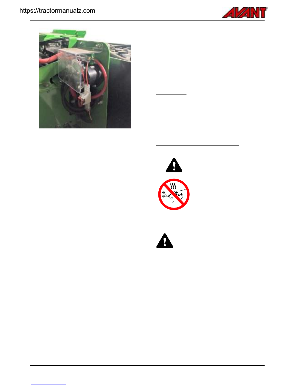
Avant e5
86
Inverter diagnostic codes
The loader is controlled via CAN bus system. The
two electric motor controllers check the electric motor
related systems during start-up of the loader.
In case the inverter that controls the auxiliary
hydraulics pump has detected a fault requiring
service, the multi function display will show a fault
code. The multi function display can display fault
codes stored by the electric motor controller of the
auxiliary hydraulics pump. Any fault code related to
the inverter of the drive pump will by displayed with
LED lights on the side of the inverter.
The electric system may go into to fault mode, which
will reduce power output to protect the battery and
electric systems. If necessary, the loader can be
driven to a safe location, but must not be loaded or
used more than absolutely necessary. The loader
must be checked and serviced by authorised service
before continuing use.
Diagnostics fault codes
Fault codes may help diagnosing a problem when
communicating with authorised service. If you see an
error code message displayed on the multi-function
display, for more information, contact your local
Avant service. Detailed iInterpretation of fault codes
and MIL reset require contact with service.
Codes start with the letter F and six numbers after it,
such as F_ _ _ _ _ _. The first number indicates the
severity of the error type:
F1 _ _ _ _ _ is an information code, that warns
about low battery or similar faults with low
severity.
F2 _ _ _ _ _ and F3 _ _ _ _ _ warn about
functional faults, such as sensor errors or if a
wrong sequence of controls is used. Restart of
the loader may solve the issue.
F4 _ _ _ _ _ indicates a severe fault that must be
repaired before continuing the use of the loader.
If there are multiple fault codes stored, the code for
the most severe fault will appear on the display.
Light bulbs
1.
Front lights
LED unit
2.
Work lights
LED unit
3
Road traffic headlights:
H7
Metal structures of the loader
Contact Avant service in case the
steel structure of the loader gets
damaged. A faulty reparation, or
wrong methods and materials used
for reparation, can cause
hazardous failures or further
damage the loader.
In case the ROPS safety frame or the FOPS
canopy of the machine gets damaged, the
machine must be taken to Avant service for
checking. It is not allowed to repair the
ROPS and FOPS.
https://tractormanualz.com

Avant e5
87
Troubleshoot
Listed below are possible causes for typical problems. In case you experience trouble with the operation of the
machine, check troubleshoot lists first and if problem is not solved, contact your nearest service point or dealer.
Problem
Possible cause
Remedy
Electric motors won't start when
turning the ignition switch
Driver not on driver's seat
Operator must sit on driver's seat to activate
auxiliary hydraulics. Also, other operating mode
can be selected to operate certain attachments
from another control position, see page 46.
Ignition switch fuse blown
The ignition switch controls also the electric main
switch of the loader. There are two fuses for the
ignition switch. Check all fuses, see page 85.
Hydraulic attachment does not
work when the auxiliary
hydraulics control lever is moved
Attachment hoses are not coupled or
the multi connector is not fully locked
Make sure that the multi connector is properly
connected.
Faulty or damaged quick couplers (will
restrict or stop oil flow)
Replace quick couplers in multi connector.
Operator not seated on driver's seat
Operator must sit on driver's seat to activate
auxiliary hydraulics. Also, other operating mode
can be selected to operate certain attachments
from another control position, see page 46.
Fault in attachment
Check with another attachment, if possible.
Attachment hoses will not go into
the extra front or rear quick
couplers of the machine
There is back pressure in the auxiliary
hydraulics line
Release the pressure by moving the extra
auxiliary hydraulics control lever in both
directions.
Hydraulic oil overheats
Control valve not fully open
Adjust the locking plate of the aux hydraulics
control lever, see page 32.
Dirty, blocked or faulty hydraulic oil
cooler
Clean hydraulic oil cooler, check fan.
Check fan fuse, temperature switch, and relay.
Overload of hydraulic system
Allow to loader cool by leaving on idle, until
hydraulic oil cooler stops. Avoid operating an
attachment at extreme load continuously. Check
that attachment is operated correctly, and no flow
restrictors are left half open on hydraulic circuit.
Low hydraulic oil level
Make sure hydraulic oil level is as shown on page
78.
Electric motors will not run
Battery discharged or damaged
Charge battery or start with separate battery.
Check battery condition, replace if necessary.
Operator presence control activated
Operator must sit on driver's seat to activate
auxiliary hydraulics. Also, other operating mode
can be selected to operate certain attachments
from another control position, see page 46.
Auxiliary hydraulics control lever is in
locking position
Release the lever to neutral position.
Blown fuse
Check all fuses
Cold temperature
The current output capacity of the battery is
reduced in extreme cold. Also, hydraulic oil
becomes thick (viscous) in cold. Combined with
low charge level the hydraulic motors may not
start running. Take the loader to warm place to
heat, and charge battery. Use high quality
hydraulic oil.
https://tractormanualz.com

Avant e5
88
Problem
Possible cause
Remedy
Drive works erratically and boom
movements do not work at all,
electric motors run
Low hydraulic oil level
Check hydraulic oil level and condition.
Drive and boom movements work
erratically, motors run smoothly
Air in hydraulic components
Move boom and steering cylinders and hold at
each extreme position to de-air the system.
Check hydraulic oil level and condition.
Hydraulic oil pushed out from
hydraulic oil filler cap, hydraulic
oil foams
Leak in hydraulic suction line
connecting tank and hydraulic pumps
allows air to sucked in
Replace suction hoses.
https://tractormanualz.com

Avant e5
89
Services made
1.
Customer
2.
Loader model
Serial number
3.
Date of delivery
Date of service
dd / mm / yyyy
Operating
hours
Remarks
Serviced by:
Stamp/signature
___/___/_____
_____/ 50 h
___/___/_____
_____/ 450 h
___/___/_____
_____/ 850 h
___/___/_____
_____/ 1250 h
___/___/_____
_____/ 1650 h
___/___/_____
_____/ 2050 h
___/___/_____
_____/ 2450 h
___/___/_____
_____/ 2850 h
___/___/_____
_____/ 3250 h
___/___/_____
_____/ 3650 h
___/___/_____
_____/ 4050 h
https://tractormanualz.com

Avant e5
90
.
Notes
.
https://tractormanualz.com

Avant e5
91
Notes
.
https://tractormanualz.com

Avant e5
92
Notes
.
https://tractormanualz.com

Avant e5 2017 1
EC DECLARATION OF CONFORMITY
DÉCLARATION DECONFORMITÉ CE
EG-KONFORMITÄTS-ERKLÄRUNG
Manufacturer:
Avant Tecno Oy
Ylötie 1
33470 Ylöjärvi, Finland
Fabricant :
Avant Tecno Oy
Ylötie 1
33470 Ylöjärvi, Finlande
Hersteller:
Avant Tecno Oy:
Ylötie 1
33470 Ylöjärvi, Finnland
Technical Construction File Location:
Same as Manufacturer
Emplacement du fichier technique de
fabrication : Le même que celui du
fabricant
Ort der technischen Bauunterlagen:
Identisch mit Hersteller
We hereby declare that the machine listed
below conforms to EC Directives:
2006/42/EC (Machinery), 2014/30/EC
(EMC) and 2000/14/EC (Noise Emission).
Nous déclarons par la présente que la
machine mentionnée ci-aprés est
conforme aur directives CE: 2006/42/CE
(machines), 2014/30/CE (CEM) et
2000/14/CE (émission de bruit)
Wir erklären hiermit, dass die
nachestehend aufgeführte Maschine mit
folgenden EG-Richtlinien in
Übereinstimmung steht: 2006/42/EG
(Maschinenbau), 2014/30/EG (EMV) und
2000/14/EG (Lärmemssionen).
Category: EARTH-MOVING MACHINERY
/ LOADERS / COMPACT LOADERS
Catégorie : ENGINS DE
TERRASSEMENT/ CHARGEURS/
CHARGEURS COMPACTS
Kategorie: ERDBEWEGUNGSGERÄT/
LADER/KOMPAKTLADER
Original language
Original language
Original language
Model / Modèle / Modell:
AVANT e5
L
Serial Number / Numéro de série / Seriennummer:
Year of manufacture / Année de fabrication / Baujahr: 2016-2017
Directive
Directive
Richtlinie
Conformity Assessment Procedure
Procédure d'évaluation de conformité
Konformitätsbewertungsvergahren
Notified body
Organisme notifié
Zugelassene Stelle
2006/42/EC
Self-certification
2006/42/CE
Autocertification
----
2006/42/EG
Selbstzertifizierung
2014/30/EC
Type-test
2014/30/CE
Examen CE de type
2014/30/EG
Baumusterprüfung
2000/14/EC
Type-test
2000/14/CE
Examen CE de type
2000/14/EG
Baumusterprüfung
e5
Sound Power Level (guaranteed) / Niveau de puissance acoustique (garanti) /
Schallleistungspegel (garantiert)
101 dB(A)
Sound Power Level (measured) / Niveau de puissance acoustique (mesuré) /
Schallleistungspegel (gemessen)
100 dB(A)
___.___.______ Ylöjärvi, Finland
Risto Käkelä,
Managing Director / Directeur général / Geschäftsführer
https://tractormanualz.com

Avant e5
Index
A
Access to electric motor
compartment - 71
Adjust and replace slide pads
of telescopic boom - 79
Adjust pressure of hydraulic
system - 81
Allow the loader to warm up
properly - 48
Attachment control switch pack
(optional extra) - 34
Auxiliary hydraulics oil flow -
23, 24, 34, 56
Avant warranty - 7
B
Ballasted tyres - 26
Battery and Charging - 16, 31,
63, 65, 82
Battery condition tests - 83
Battery connector - 14, 82
Battery disconnect switch - 45
Battery life - 64
Battery maintenance - 82
Battery maintenance - water
refill - 68
Battery system in cold
environment - 48
Battery systems on e5 - 14
Battery water level indicators -
68
Battery watering system - 68
Boom floating - 31, 39
Boom self-levelling - 39
C
CAB L (optional extra) - 38
Cab Safety - 38
Changing of hydraulic oil filter -
78
Charge process - 66
Charger - 66
Charger plug type - 66
Charging the battery - 65
Check and tightening of bolts,
nuts and fittings - 77
Check battery visually - 83
Check pressure of hydraulic
system - 80
Clean cooling fans and
surfaces - 79
Cleaning of battery - 82
Cleaning of the machine - 76
Control lever of auxiliary
hydraulics (hydraulically
operated attachments) - 32,
45, 61, 87
Control lever of boom and
bucket - 30, 32
Control of loader boom,
auxiliary hydraulics and
other functions - 32
Controls and options of the
Loader - 30
Counterweights - 40, 50
Coupling adapters - 59
Coupling the attachments - 57
Coupling the hydraulic hoses
of the attachment - 60
D
Daily inspections - 44, 73
Dashboard - 31
Dashboard e5 - 30, 31, 39, 66
Description of the loader - 17
Dimensions - 22
Drive control - 46
Drive pedals - 47
Drive release and anti slip - 47
Drive speed and pulling force -
24
Drive while charging - 67
Driving/operating modes - 47
E
Electric 12 V outlet - 30, 35
Electric qualification - 6
Electric system & fuses - 85
Electric system and battery -
23
Electric system and handling of
the battery pack - 14, 65, 68
Ensure full charge - 82
Extra auxiliary hydraulics
coupling - 62
Extra auxiliary hydraulics outlet
- 30, 41
Extra work light kit (option) - 37
F
Filters - list of filters - 78
Fire prevention - 13
First aid measures - 15
Follow correct charging
procedure - 15
Foreword - 3
G
General safety instructions - 8
General specifications - 23
Greasing of the machine - 73,
76
H
Hand throttle lever for pump
RPM control - 30, 34
Handle battery with care - 14
Handling of heavy loads - 50
Height and width - 22
How to estimate actual lifting
capacity - 51
Hydraulic attachment coupling
- 30, 58
Hydraulic oil change - 78
Hydraulic oil cooler fan fuse -
31, 85
Hydraulic oil level - 78
Hydraulic oil type - 78
I
Ignition key - 44
In case the machine tips over -
52
Indicator lights - 31
Installing of service support
and frame lock - 72
Intended use - 5
Introduction - 3
Inverter diagnostic codes - 86
J
Joystick - 6 function (optional
extra) - 33
K
Keep this manual with the
loader - 6
L
Lifting - 8, 54
Light bulbs - 86
Lights - 37
Loader maintenance - 76
https://tractormanualz.com

Avant e5
M
Main parts of the loader - 18
Main switch - 45
Maintenance schedule - 75
Make sure all relevant manuals
are available - 4, 73
Material handling - 27, 33, 50
Metal structures of the loader -
86
Modifications - 12
Multi-function display - 30, 35
N
Notes - 90, 91, 92
O
Operating instructions - 43
Operation on uneven surfaces,
gradients, and near
excavations - 11
Operator presence control -
30, 34, 44, 46, 61, 87
Operator qualification - 6
OptiDrive™ - 47
Options - 39
P
Parking brake switch - 30, 35
Personal safety and protective
equipment - 12
Preparation for charging - 65
R
Rated operating capacity - 29
Rear carrier - 41
Recharge - General principles
- 63
Recharge daily - 82
Refill battery water level - 82
Releasing the residual
pressure of hydraulic system
- 8, 45, 62
Replacing battery pack - 84
Requirements for attachments
- 56
Reverse buzzer (option) - 41
S
Safe stopping procedure - 45
Safety First - 8
Safety frame (ROPS) and
safety canopy (FOPS) - 12
Safety instructions - 70
Seat - Seat belt and seat
adjustments - 36
Seat adjustments - 36
Seat heater - 36
Service and maintenance - 9,
70
Services made - 89
Signs and decals - 19
Snow chains - 26
Starting the loader - 44
Steering of the machine - 49
Stopping the loader (Safe
stopping procedure) - 45, 50
Storage - 55
Storage of electric loader - 55
Suspension seat - 36
T
Technical specifications - 22
Telescopic boom control lever
- 30, 33
Tie down options - 54
Tie down points - 53
Tipping load - 27, 29, 33
Tipping load - load chart - 28
Tips to increase battery life -
45
To keep the battery in good
condition - 64
To start the loader: - 45
Towing (retrieval of the
machine) - 55
Trailer coupling - 40
Transport instructions and tie
down points - 53
Troubleshoot - 31, 45, 87
Tyre pressure check - 77
Tyres - 25
U
Using the auxiliary hydraulics -
61
W
Warning beacon (option) - 30,
37
Watering procedure - 69
Wheel spacers - 25
When you want to have a high
pulling force: - 47
Windscreen washer and wiper
- 30, 38
Work lights - 37
Working near powerlines - 13
Working with attachments - 56
https://tractormanualz.com
AVANT has a policy of continuous development, and retains the right to change specifications without notice. © 2017 Avant Tecno Oy. All rights reserved.
www.avanttecno.com
https://tractormanualz.com
 Loading...