


Backhoe 220 250 2011 1
Operator’s
Operator’sOperator’s
Operator’s
manual for Attachment
manual for Attachmentmanual for Attachment
manual for Attachment
Backhoe 220 & 250
Product number: 400-700-series loaders: A21172
A21155
Please read this manual carefully before using the equipment, and follow all
instructions.
Keep this manual for later reference.

Backhoe 220 250 2011 1
CONTENTS
1. Foreword..............................................................................................................................................3
2. Designed purpose of use ......................................................................................................................3
3. Safety instructions for the backhoes......................................................................................................3
4. Backhoe specifications..........................................................................................................................4
5. Assembly of the backhoe......................................................................................................................5
5.1.Mounting kit A48130.......................................................................................................................6
5.1.1.Contents of the mounting kit......................................................................................................6
5.1.2.Mounting the lower adapter brackets for hydraulic locking.........................................................6
5.1.3.Mounting the valve support bracket...........................................................................................7
5.2. Mounting the backhoe to the loader.................................................................................................8
5.2.1.Taking the backhoe off from the loader......................................................................................9
5.3. Connecting and disconnecting the hydraulic fittings.........................................................................9
5.4. Control valve of the backhoe...........................................................................................................10
5.5. Mounting a bucket on the backhoe..................................................................................................10
5.6. Grading bucket ...............................................................................................................................10
6. Instructions for use................................................................................................................................11
6.1. Using the outriggers........................................................................................................................11
6.2. Using the hydraulic locking of the backhoe......................................................................................11
6.3. Digging with the backhoe................................................................................................................12
7. Inspections, maintenance and servicing................................................................................................13
7.1. Cleaning the equipment ..................................................................................................................14
7.2. Lubricating......................................................................................................................................14
8. Warranty terms.....................................................................................................................................15
Appendix: EC Declaration of Conformity
This manual uses the following warning symbols to indicate factors that must be taken into account to reduce
the risk of personal injury or damage to property:
This safety symbol refers to important safety information in this manual. It
warns of an immediate hazard that could cause serious personal injury or
damage to property.
Read the warning text accompanying the symbol carefully and ensure that
other operators are also familiar with the warnings, since personal safety is
at stake.
This notice symbol indicates information about the correct operation and
maintenance of the equipment.
Failure to observe the instructions accompanying the symbol can lead to
equipment breakdown or other property damage.
In addition to the safety instructions included in this manual, you must observe all occupational safety
regulations, local laws and other regulations concerning the use of the equipment. Due to continuous
product development, some of the details in this manual may differ from your equipment. We reserve the
right to change the contents of the manual without notification. This operator’s manual is a translation of the
original Finnish version.

3(18)
1. Foreword
Avant Tecno Oy would like to thank you for your purchase of this AVANT attachment. It has been designed
and manufactured on the basis of years of product development and experience. By familiarising yourself
with this manual and following the instructions, you ascertain your safety and ensure the reliable operation
and long service life of the equipment. Read the instructions carefully before starting to use the equipment or
performing maintenance.
The use of the backhoe requires some previous experience of operating the loaders. These instructions
include important instructions about mounting and using the backhoe for experienced AVANT operators as
well. Ensure that all persons using the equipment have received proper guidance and familiarised
themselves with the manual and all safety instructions before using the equipment. Keep this manual at hand
throughout the service life of the equipment. If the manual is lost, you can request a new one from the retailer
or manufacturer. If you sell or transfer the equipment, be sure to hand over this manual to the new owner.
2. Designed purpose of use
The AVANT backhoes 220 and 250 are attachments designed and manufactured to be used with AVANT
multi purpose loaders. They are digging attachments with high reach, and they are suited for hard
construction work, to be used in digging and loading of soil to a trailer, for example.
The slewing range of both models is full 180° with constant speed. The backhoe is easy and quick to mount
on the loader, and the hydraulically operated locking bar, which mounts on the loader chassis, ensures
stability during digging and enables efficient work. In addition, manually adjustable support jacks are a
standard feature.
The backhoes are equipped with a hydraulic control valve unit to control the movements of the backhoe. The
backhoes can be operated by standing next to the equipment, or directly from the driver’s seat, when the
control valve unit is mounted on the loader boom. A comprehensive range of buckets is available for various
jobs. Also a grading bucket with hydraulic tilting is available, for which the backhoe is equipped with
necessary components as standard. The use of the backhoe as a lifting crane is prohibited due to a risk of
tipping the loader-backhoe combination over. The backhoes are not suitable for dredging.
The attachments have been designed to require as little maintenance as possible. With the backhoe, an
installation kit is provided, which is mounted at the first use. Regular maintenance tasks can be performed by
the operator. More demanding tasks must be left to qualified professionals. Appropriate protective equipment
and original spare parts must be used for the maintenance. Read the maintenance and servicing instructions
in this manual. Please contact your AVANT retailer if you have additional questions about the operation or
maintenance of the equipment or if you require spare parts or maintenance services.
3. Safety instructions for the backhoes
Please bear in mind that safety is the result of several factors. The loader-attachment combination is highly
powerful, and improper or careless use may cause serious personal injury or property damage. Due to this,
you should carefully familiarise yourself with the manuals of both the loader and the attachment before
starting operation. Do not use the attachment if you have not familiarised yourself with its operation and the
related hazards. The purpose of these instructions is to help you to:
• use the equipment in a safe and efficient manner
• monitor and prevent any hazardous situations
• keep the equipment intact and ensure a long service life
• When mounting the attachment to the loader, ensure that the locking pins of the
loader's quick attach plate are in the lower position and that they have locked the
attachment to the loader. Always mount also the supporting bracket. Carefully
read the instructions of how to attach the backhoe to the loader.

4(18)
• Start the use of the backhoe carefully and calmly at a safe area
• Keep others away from the operating area of the backhoe due to crushing hazard.
• Turn the auxiliary hydraulics of the loader off immediately after active use of the
backhoe to prevent accidental movements of the backhoe.
• Do not use the backhoe on horizontally tilted terrain. Ensure the stability of the backhoe
and the load carrying capacity of the ground even at level terrains. Adjust the outriggers
correctly and use the hydraulic locking of the backhoe.
• Pay attention to the contours of the terrain and other hazards, such as rocks or
branches and trees reaching the driver's seat or the backhoe control levers. Pay
attention to the surroundings and any other persons and machines moving in the
vicinity.
• Always transport the backhoe as low and as close to the machine as possible to keep
the centre of gravity low. For transporting, turn the boom of the backhoe to its middle
position and keep the bucket near the loader.
• Turn the backhoe to a position in which it will be stable during storage. See section 5.
• Shut down the loader engine before any cleaning, maintenance or adjustments. Ensure
that the backhoe is supported properly supported when going near the attachment.
• Do not modify the structure of the attachment in a manner that would affect its safety.
• Also read the safety instructions for the loader in the loader manual.
Note that the backhoe and the loader boom move down even if the engine has been
stopped. Never go under a raised boom or the attachment.
Familiarise yourself with the loader controls in a safe area. Pay particular attention to
the safe stopping of the attachment and the machine.
Remember to wear proper protective clothing:
• The noise level in the driver's seat exceeds 85 dB(A). Wear hearing protection while
working with the loader.
• The use of safety boots is recommended while working with the loader.
• Wear protective gloves when handling hydraulic hoses.
•
4. Backhoe specifications
Table 1 – Backhoe 220 & 250 technical data
Product number A21172 A21155
Digging depth: 2 200 mm 2 500 mm
Loading height: 1800 mm 2100 mm
Weight (without bucket): 350 kg 370 kg
Installation kit for 400-700 –series loaders: A48130
Installation kit*:
Installation kit for 300 –series loaders and
500-series manufactured before 2008: A48132

5(18)
*Normally the installation kit A48130 is supplied with the backhoe.
The installation for 300-series loaders and 500-series, manufactured before 2008, depends on the
boom type. Contact AVANT dealer for more information.
Table 2 – Bucket options
Product number: A2896 A2887 A2932 A2871
Width: 280 mm 400 mm 1000 mm
Listed below are the markings and labels fastened to the flail mower, which must be visible on the
equipment. Replace the warning labels, if they have become unclear or detached completely. New labels are
available via your retailer or contact information provided on the cover page.
The warning decals contain important safety information. Replace damaged or
missing decals with new ones.
• A46771 – Read the instructions before use.
• A46772 – Do not go under a raised attachment; keep a safe
distance from raised or freestanding equipment.
• A46803 – Crushing hazard, keep clear of moving parts.
• A46797 – Crushing hazard in the reach area of the backhoe,
keep bystanders away from danger area.
Grading bucket with
hydraulic tilting, 700 mm
Identification plate of the attachment
A46771 A46772 A46803 A46797
5. Assembly of the backhoe
The backhoes 220 and 250 are delivered with a loader model dependent installation kit. Before the first use
the installation kit must be mounted on the backhoe and the loader. When the backhoe is ready for use,
mount it on the loader as shown in the next sections, and mount the bucket to the backhoe.
Beware of the hinged control valve support on the loader. Do not remove the valve
unit from its stand until the backhoe is completely mounted to the loader.

6(18)
5.1. Mounting kit A48130
These instructions for the mounting kit A48130 are applicable to all 400-, 600-, and 700-series loaders, as
well as to 500-series loaders manufactured in 2008 or later. Contact your AVANT dealer if using the backhoe
with other loader models.
5.1.1. Contents of the mounting kit
The mounting kit contains the following
loader dependent components:
1. Supporting bracket kit to be
mounted on the loader, inc. pins
and locking cotter pins
2. Control valve unit mounting
bracket, its adapter and mounting
supplies
3. Adapters (2 pieces) for
attachment hydraulic locking,
bolts, washers and nuts
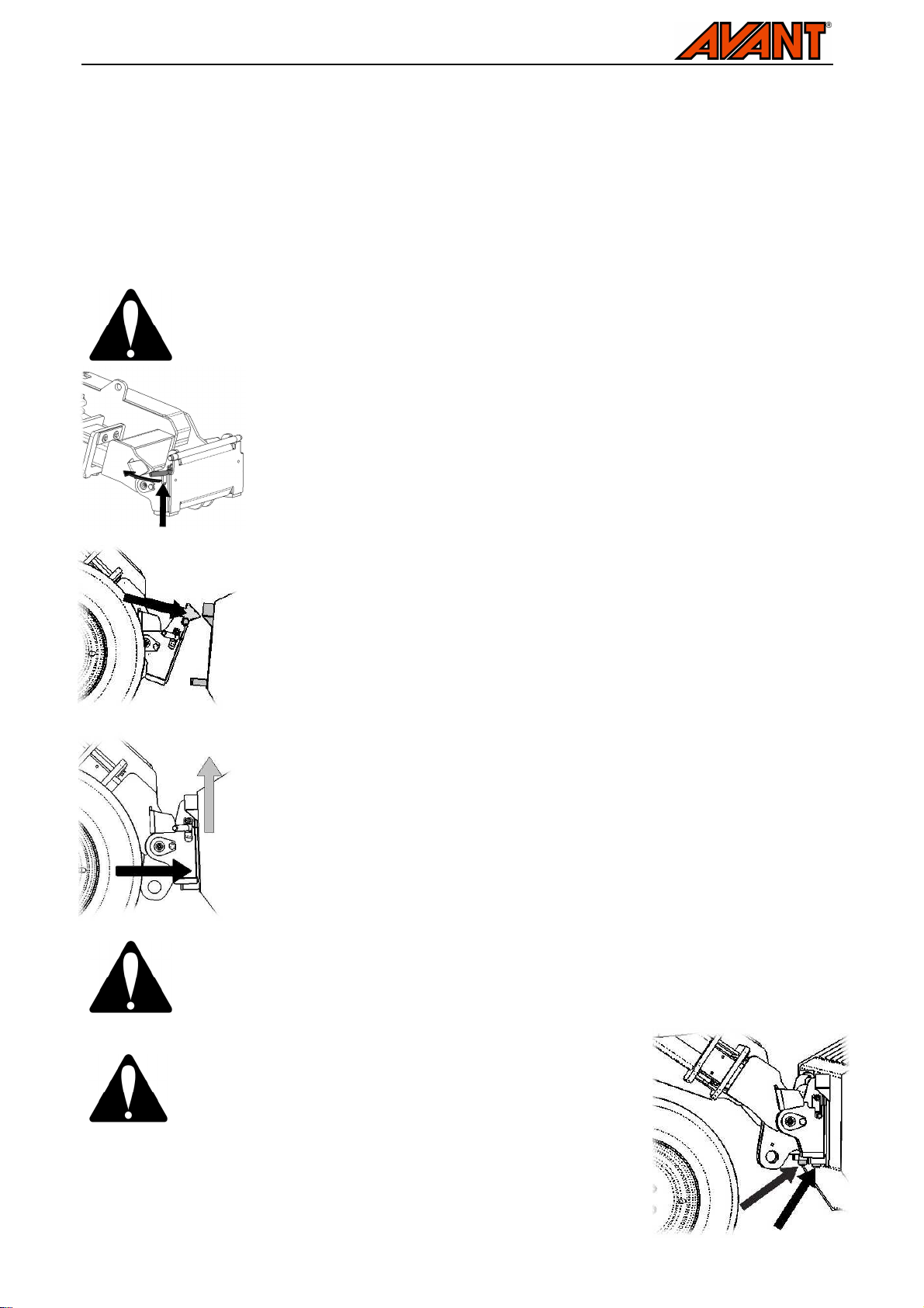
5.1.2. Mounting the lower adapter brackets for hydraulic locking
The backhoes are hydraulically locked to the front frame of the
loader by the brackets, which are turned against the underside
of the loader. Before putting the backhoe into service, the lower
adapter brackets must be mounted.
The locking adapters (see figures on the right and below) are
mounted to below the quick attach plate. The brackets should
be mounted to the outer side of the backhoe frame brackets.
The convex edge of the bracket should face upwards.
Locking adapter’s mounting holes:
1: mounting holes for 400-600-series loaders
2: mounting holes for 700-series loaders
Mount the lower adapter brackets with the provided M14 sized bolts and nyloc nuts. Use washers on both
the bolt and the nut side of the fixing.

7(18)
When the holding bracket is in its place, tighten the
Do not overtighten the screws!
Fit the valve holder to the holding bracket as
5.1.3. Mounting the valve support bracket
The backhoe can be operated from two operating positions. The control valves are mounted to the loader so
that it can be operated by standing next to the loader, or the valve may be mounted on the loader boom to
be operated from the driver’s seat. To mount the valve on the loader boom, an assembly kit must be
mounted on the boom. The assembly kit can be left on the boom for easier attachment of the backhoe the
next time it is used.
To make it easier to mount the assembly kit, lift the
loader boom and mount the service support of the
loader boom. Take up the items shown in the
adjacent figure.
Use the service support of the
loader boom during installing of the
valve mounting bracket.
.
Remove the pin holding screw from the
upper end of the loader boom, shown
in the left figure.
Mount the holding bracket on the boom
and replace the removed screw with
the longer screw provided with the kit.
screws on the right side of the bracket against the
laoder boom.
shown in figure below.
8(18)
5.2. Mounting the backhoe to the loader
Mounting the backhoe to the loader must be done carefully. The backhoe may tip over on the loader or the
operator, if it has not been properly attached. To prevent hazardous situations, always follow the attachment
mounting instructions provided in the following pages. Also remember the safety instructions in Section 3.
The attachment is mounted to the loader boom by using the quick attach plate and the counterpart on the
attachment. In addition to this, a locking bracket must be also installed. The backhoe is mounted to the
loader as follows:
Never move or raise an attachment that has not been locked.
Step 1:
• Lift the quick attach plate locking pin / locking pins up and turn them backwards
into the slot so that they are locked in the upper position.
• Ensure that the hydraulic hoses are not in the way during installation.
Step 2:
• Turn the quick attach plate hydraulically to an obliquely forward position.
• Drive the loader onto the attachment. If your loader is equipped with a
telescopic boom, you can utilise this.
Step 3:
• Lift the boom slightly – pull the boom control lever backward to raise the
attachment off the ground.
• Turn the boom control lever left to turn the bottom section of the quick attach
plate onto the attachment.
• Lock the locking pins manually – do not use the automatic returning of the
locking pins.
Do not use the automatic locking of locking pins with the backhoe. The centre of
gravity of the backhoe is at relatively high, which creates a risk of the backhoe tipping
over. Lower the attachment on the ground and secure the locking manually.
Before moving or lifting the attachment, ensure that the
locking pins are in the lower position and come through the
fasteners on both sides.

9(18)
Step 4: Fitting the support bracket
• Lift the backhoe slightly off the ground. Remove
the pin from the loader side of the supporting bracket and place the
bracket on the bracket of the loader boom.
• Tilt the backhoe to align the holes.
• Fit the locking pin through the holes and lock it
with the cotter pin.
Do not use your fingers to check the alignment of the support bracket. Movement of
the backhoe creates a pinch or shear hazard.
5.2.1. Taking the backhoe off from the loader
When taking the backhoe off from the loader for storage, to ensure its stability, do as follows:
1. Open the hydraulic locking completely (see section 5.4)
2. Lower the outriggers of the backhoe on even and solid
surface.
3. Turn the slewing of the backhoe to its middle position and
lower the bucket just slightly above the ground, as shown
in the adjacent figure.
4. Turn the auxiliary hydraulics control of the loader off.
5. Put the control valve of the backhoe to its holder on the
backhoe. Note that the backhoe may move if the control
levers are actuated.
6. Turn the loader boom tilting so that it s possible to
remove the pin of the support bracket.
7. Shut down the loader engine and remove the support
bracket
8. Tilt the backhoe to a slightly forward position so, that the bucket will now lower on the ground.
9. Disconnect the hydraulic fittings as shown in section 5.3. This procedure will release the pressure left in
the backhoe and the bucket and the backhoe booms will lower to a stable position.
10. Open the quick coupling and take the backhoe off from the loader.
Backhoe storage position
5.3. Connecting and disconnecting the hydraulic fittings
Before connecting or disconnecting hydraulic fittings, shut down the loader engine and move the auxiliary
hydraulics lever on the loader to its extreme positions a few times and also move the control levers of the
backhoe. This way, there will be no remaining pressure in the system and the fittings are easy to connect.
To connect and disconnect the fittings, move the collar at the end of the female fitting. The hoses should be
connected so that the male fitting of the backhoe is connected on the loader to the fitting with coloured cap.
The second hose is connected on the single male fitting of the loader.
When disconnecting the fittings, first move the auxiliary hydraulics control levers as well as the levers of the
backhoe. Lower the backhoe as described in the previous section so that there will be no residual pressure
in the system and the backhoe will be stable during storage.
If there is residual pressure in the hydraulic system of the backhoe due to its position, it is often possible to
disconnect the fittings, but connecting them the next time may be difficult. If the fittings will not connect, the
residual pressure must be released. First move the control levers of the backhoe. Note that the backhoe may
move. If this doesn’t help, while the backhoe is coupled with the loader, its bucket may be pressed against
the ground with the loader boom.
10(18)
In other cases the pressure left in the system must be relieved by opening the hose fitting slightly with tools.
Keep both of the hoses disconnected and wrap the fitting in a cloth to prevent oil spillage. When the fitting is
opened slightly, a small amount of oil will be released; beware of the oil. Wear protective gloves and goggles.
Tighten the fitting immediately after the procedure.
The backhoe may move when the pressure is released, stay clear from the danger
area. To prevent oil spillage wrap the fitting with cloth when releasing pressure from
the hoses.
When removing the attachment, always disconnect the hydraulic fittings before
detaching the quick attach plate, to prevent hose damage and any oil spills. Reinstall
the protective caps on the fittings to prevent impurities from entering the hydraulic
system.
Never connect or disconnect quick couplings or other hydraulic components while the
system is under pressure. High-pressure fluid ejection may cause injuries.
Keep the fittings as clean as possible; use the protective caps for the quick couplings on both the attachment
and the loader. Dirt, ice, etc. may make using the fittings significantly more difficult. Note that the protective
caps on the loader and the attachment can be fastened to each other during operation to reduce the
accumulation of dirt. Never leave the hoses hanging on the ground; place them on top of the equipment.
5.4. Control valve of the backhoe
In larger excavation tasks and constant changing of location it is advisable to mount the control valve on the
bracket on the loader boom that is included in the installation kit of the backhoe. The backhoe may be
operated from the control position next to it in tasks demanding accuracy or when visibility is hindered, or
when using the backhoe only for a little while. Move the control valve back to its place on the backhoe before
taking the backhoe off from the loader.
To prevent unintended movements of the backhoe shut down the loader and lower the
bucket of the backhoe onto ground before starting to move the valve. Make sure that
the valve is securely locked on the selected operating position with the locking screw.
On loaders equipped with cabin L, LX or DLX, the lower section of the windscreen must
be removed to make it possible to mount the valve on the boom.
5.5. Mounting a bucket on the backhoe
The buckets are connected to the backhoe with two pivot pins. Change the bucket when the backhoe is
mounted to the loader. Place the bucket near the ground. Ensure that the backhoe is adequately supported.
Hold the bucket while removing it and use a soft hammer or a block of wood to soften the hits, so that the
pins will not get damaged. Do not hit directly at the pins.
5.6. Grading bucket
With the grading bucket it is easy to level the ground surface to desired slopes or to dig a ditch. The
backhoes are equipped with necessary components to fit and operate the grapple bucket; the control valve
has the needed block and lever for the bucket. To mount the grading bucket, also hydraulic quick couplings
should be mounted on the backhoe. Contact service if needed.

11(18)
6. Instructions for use
When the installing kit of the backhoe and the backhoe are mounted on the loader the work can be started.
The control levers of the backhoe will operate once the auxiliary hydraulics of the loader has been locked on.
Use the outriggers and the hydraulic locking of the backhoe; their operation is shown on the following pages.
Check the operating area and the attachment once more before starting work.
• Check that the backhoe is intact and that all obstacles have been removed from the working area
before operation. Remember correct working methods and avoid unnecessary descending from the
loader.
• Make sure that it safe to dig in the location. Find out if there are electric cables, water lines or similar
obstacles at a depth that can be reached with the digger.
• Operate the backhoe only at well-lit areas.
• Ensure that the loader and attachment are used in a safe manner and as intended.
• Check the hydraulic hoses and their connections and that the hoses are not subjected to stretching
or squeezing at any position of the backhoe. Check regularly to ensure there are no hydraulic leaks.
Refer to Section 7 for maintenance instructions.
• Operate the attachment only from the driver's seat or the operating position at next to the backhoe.
Do not let others to use the controls when working near the backhoe.
Turn the auxiliary hydraulics off whenever not operating the backhoe or when
transporting the backhoe. The control levers of the backhoe may be accidentally
operated, so that accidental movement of the backhoe may create a hazardous
situation.
Never go under a raised boom or the attachment. The backhoe components and the
loader boom move down even if the engine has been stopped.
6.1. Using the outriggers
The backhoe is equipped with outriggers, which are intended to stabilize the backhoe during digging and
moving material to the sides. Using the backhoe is more efficient with the use of the outriggers, so it is
advisable to set them correctly. The outriggers are mounted so that its foot points forward from the loader.
Note that the left and the right ones are dissimilar.
The correct setting of the outrigger will also affect the hydraulic locking shown in the next section. The height
of the outriggers should be adjusted according to the terrain. There are several holes on the backhoe frame
and the outrigger. Use the cotter pin to lock the adjustment pin.
6.2. Using the hydraulic locking of the backhoe
For more rigid mounting of the backhoe, it is locked onto the loader front frame by hydraulically operated
brackets. When the backhoe, its support bracket and hydraulic hoses are connected, the telescopic boom
of the loader must be retracted completely.
Lower the loader boom to as down as possible, which will lead to raising the loader front wheels off the
ground about 10 cm, if the outriggers are adjusted correctly. When using the hydraulic locking, the weight of
the front of the loader will be on the outriggers, giving more stability. Note that because of the support
bracket, on loaders equipped with the self-parallel system, the loader boom control lever should also be
moved sideways to lower or to lift the backhoe.
12(18)
The locking is operated with the extra lever on the right of the control valve, shown in figure on the next
page. The lever will move the brackets mounted under the backhoe and they are intended to be turned
against the bottom of the loader front frame.
Before the first use ensure that the
locking brackets are adjusted so
that they lean against even surface
under the loader front frame, and
not against bolt ends or similar
edges. Adjust the brackets if
needed.
For the best stability use the outriggers and the locking as described.
To avoid necessary load being applied on the loader boom structures do not try to
operate he loader boom while the locking is engaged. Open the hydraulic locking
before using the boom control lever.
6.3. Digging with the backhoe
Check the operating area before starting to work:
• Ensure that there are no other persons at the work site. Do not allow others closer
than five meters from the backhoe, near the danger area of the boom or directly in
front of the backhoe.
• Make sure that it is safe to dig at the site. Find out if there are any electric cables,
water lines or similar obstacles within the reach of the equipment.
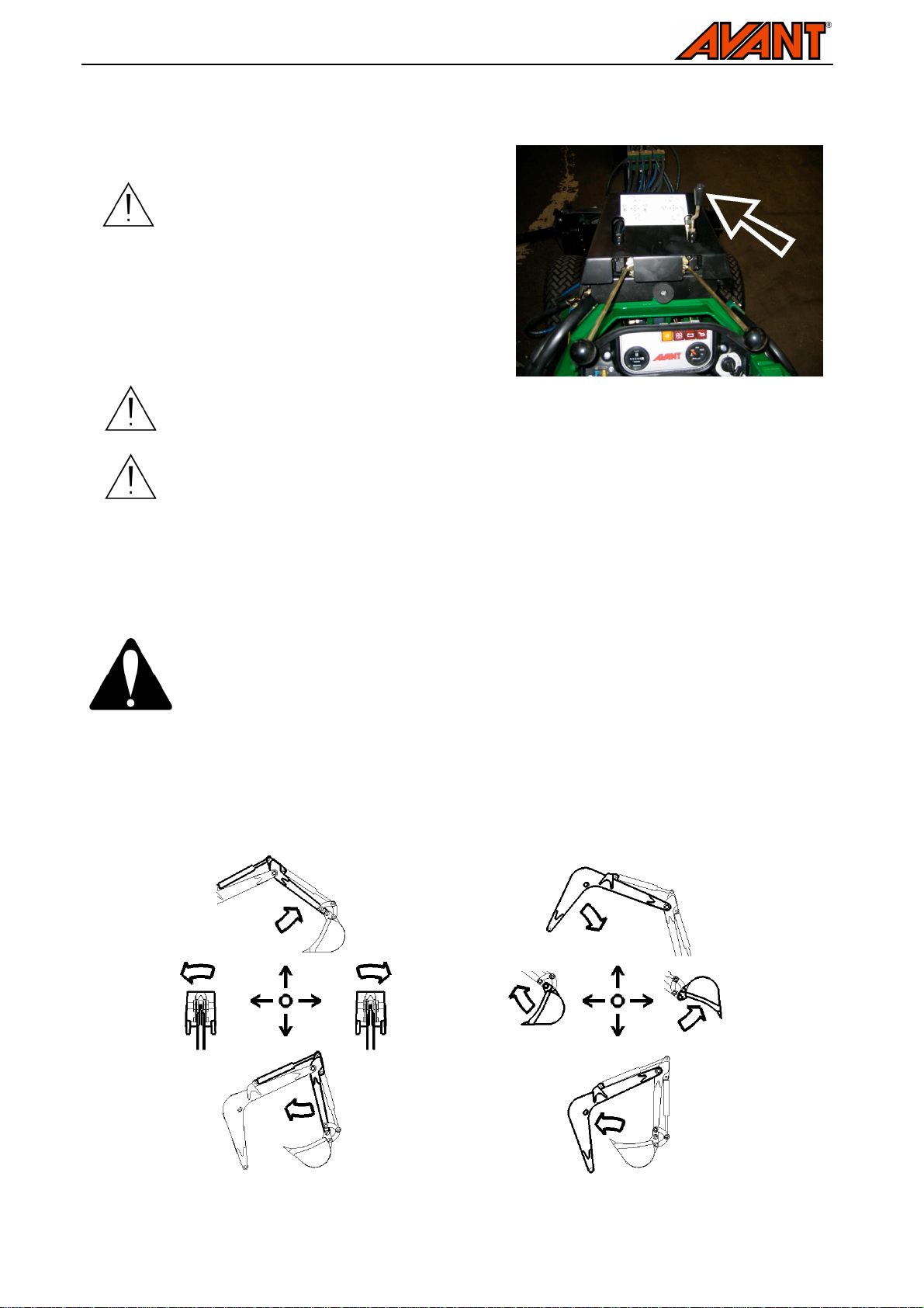
The backhoe is controlled with its two control levers. The operation of the control levers is shown in the figure
below. The backhoe has relatively many simultaneous movements, and it is advisable to familiarise the
operation with time and away from other persons or buildings.
Backhoe controls, left and right control lever

13(18)
Beware of the caving in hazard at the excavation and around it. Do not drive near the
edge of the hole or allow children to play near it.
Do not operate the backhoe at horizontally overly tilted terrains. Transport the backhoe
as low and close to the loader as possible. Drive carefully on inclined terrains.
Drive the loader so that digging is performed from front of the loader. On inclined terrains avoid excess
pulling from the sides, which can affect the stability of the loader.
Digging with the backhoe is the most efficient when the edge of the bucket is kept at an angle that allows the
edge to cut the soil the most effectively. Pull the edge of the bucket towards the loader with the left lever and
tilt the bucket by operating the right control lever at the same time. The bucket should not be pressed too
hard downwards, since this would result in lifting the front tires of the loader, and digging becomes
ineffective.
When operating with the backhoe, moderate engine revolutions are often enough. Higher revolutions will not
increase the digging force. Keeping the engine revolutions moderately low will save fuel; keep the
revolutions just high enough so that the engine will not stall.
At the first use the movements of the backhoe may be imprecise as there might be air trapped in the
hydraulic components. The hydraulic system will bleed itself, when moving all the movements to their
extreme positions.
When lifting a load from a high level, the loader could tip forward when reversing with
the loader. Do not reverse the loader while simultaneously dragging the load. Make
sure that the loader can lift and handle the load being lifted. Drive carefully on rough
terrains and keep the load as low and as close to the loader as possible.
Do not use the backhoe without the supporting bracket. The purpose of the bracket is
to lock the tilting and to make the backhoe more stable for more effective operation.
7. Inspections, maintenance and servicing
Continuous maintenance of the backhoe includes regular cleaning and lubricating. The condition of the
hydraulic hoses and components should be monitored. Due to crushing hazard caused by the moving
components of the backhoe, all maintenance work must be done when the backhoe has been lowered down
completely, its residual pressure is released and the loader is shut down.
Ensure that the backhoe is properly supported before any maintenance work. Note that
the backhoe may move also when the loader has been shut down and watch out
pinching of fingers or hands in particular.
Check the condition of the hydraulic hoses and components when the engine has been turned off and the
pressure has been relieved. Repair all leaks immediately after detecting them; a small leak can quickly grow
into a big one. Do not use the equipment, if you have discovered a fault in the hydraulic system. Leaking
hydraulic fluid may penetrate the skin and cause serious injuries. Hydraulic fluid is also harmful to the
environment.

14(18)
Lubricating points of the upper
Lubricating points of the lower
Lubricating points of the
Check hoses visually for cracks or abrasions. Monitor the wearing of the hoses and stop the use, if the
surface layer of the hose has worn off. If there are signs of leaking, to check the component, hold up a piece
of cardboard in the area where a leak is suspected. Finding any of these faults means that the hydraulic
hose or component in question must be replaced. Spare parts are available from your nearest AVANT
retailer or service point.
Never tighten a hydraulic fitting under pressure,
since the fitting may break and the released oil
may cause serious injuries. Do not use the
equipment, if you have discovered a fault in the
hydraulic system.
7.1. Cleaning the equipment
You may use a pressure washer and a mild detergent to clean the backhoe. Do not use strong solvents or
spray directly at the hydraulic components or at the labels on the attachment either. Lubricate the lubrication
points on the attachment after washing.
Do not let water to stay in the bucket. For longer storage periods touch up the paint where needed, grease
the lubrication points and oil the visible parts of hydraulic cylinder shafts to prevent rust damage. Do not
store the attachment directly against the ground; place it on blocks of wood or on a pallet, for example.
7.2. Lubricating
The lubricating of the backhoe consists of lubricating the 14 lubricating points of the backhoe and the slewing
chain. A small amount of lubricant should be added every 5-10 hours of use. The locations of the lubrication
points are shown in the figures below. All lubrication nipples are standard R1/8” nipples, replace any
damaged nipples.
Lubricate the also the slewing chain with suitable oil when the lubricating points are greased. Lubricate the
chain also when storing the backhoe for longer storage periods to prevent rust damage.
part of the main boom
part of the main boom
slewing joint

Lubricating points of the bucket linkage Lubricating points of the front boom
Lubricant must be added approximately every 5-10 operating hours. Clean the end of
the nipple before greasing. Only add the grease amount of a couple of grease press
pushes at a time.
15(18)
8. Warranty terms
Avant Tecno Oy grants a warranty of one year (12 months) for the attachment from the date of purchase.
The warranty covers repair costs as follows:
• Work costs are covered, if the repair is not performed at the factory.
• The factory replaces any defective components or consumables.
The factory may reimburse the price of components purchased by the customer in special cases that have been agreed in
advance.
The warranty does not cover:
• Normal maintenance work, such as the replacement of blades or the belts, or parts and consumables required for it.
• Damages caused by unusual operating conditions or ways of use, negligence, structural changes made without the
consent of Avant Tecno Oy, use of non-original parts or lack of maintenance.
• Consequences of a defect, such as interruption of work or other possible additional damages.
• Travel and/or freight costs caused by the repair.

Backhoe 220 250 2011 1
EY-vaatimustenmukaisuusvakuutus
EG-försäkran om överensstämmelse
EC Declaration of Conformity
EG-Konformitätserklärung
Valmistaja / Tillverkare / Manufacturer / Hersteller: AVANT TECNO OY
Osoite / Adress / Address / Adresse: Ylötie 1
33470 YLÖJÄRVI, FINLAND
Vakuutamme täten, että alla mainitut tuotteet täyttävät konedirektiivin turvallisuus- ja terveysvaatimukset (direktiivi
2006/42/EY muutoksineen). Seuraavia yhdenmukaistettuja standardeja on sovellettu:
SFS-EN ISO 12100-1, SFS-EN ISO 12100-2, SFS-EN 982, SFS-EN 474-4
Vi försäkrar härmed att nedan beskrivna produkter överensstämmer med hälso- och säkerhetskrav i EG-maskindirektiv
(EG-direktiv 2006/42/EG som ändrat). Följande harmoniserade standarder har tillämpats:
SFS-EN ISO 12100-1, SFS-EN ISO 12100-2, SFS-EN 982, SFS-EN 474-4
We hereby declare that the products listed below are in conformity with the provisions of the Machinery Directive
(directive 2006/42/EC as amended). The following harmonized standards have been applied:
SFS-EN ISO 12100-1, SFS-EN ISO 12100-2, SFS-EN 982, SFS-EN 474-4
Wir erklären hiermit, dass die nachstehend aufgeführte Maschine konform ist mit den Bestimmungen der EG-
Maschinenrichtlinie (EG-Richtlinie 2006/42/EG mit Änderungen). Die folgende harmonisierte Normen wurden angewandt:
SFS-EN ISO 12100-1, SFS-EN ISO 12100-2, SFS-EN 982, SFS-EN 474-4
Kuvaus: Avant-kuormainten kanssa käytettävä kaivuulaite
Beskrivning: Grävaggregat; arbetsredskap för Avant lastare
Description: Backhoe bucket; attachment for Avant loaders
Beschreibung: Anbaubagger; Anbaugerät für Avant Radlader
Mallit / Modeller / Models / Modellen:
Avant
Kaivuri
Grävaggregat
Backhoe
Anbaubagger
Mallit / Märken / Models / Modellen: 300-700 series
ilman kauhaa
220
250
utan skopa
without bucket
ohne Schaufel
ilman kauhaa
utan skopa
without bucket
ohne Schaufel
A21172
A21155
Allekirjoitus / Namnteckning / Signature / Unterschrift: ____________________10.6.2010 Ylöjärvi, Finland
Risto Käkelä,
Toimitusjohtaja / Verkställande direktör /
Managing Director / Geschäftsführer


 Loading...