

Page 1
Cutter Bar Mower 2014 1
Please read this manual carefully before using the equipment, and follow all
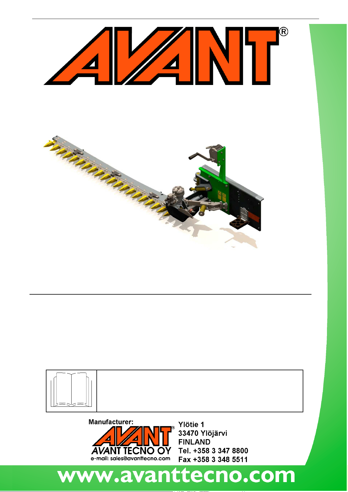
Cutter Bar Mower
Operator’s Manual for Attachment
Product number: for 300-700 –series Avant loaders: A35676
for 200–series Avant loaders: A35790
instructions.
Keep this manual for later reference
Avant Tecno Oy 2014 Copyright all rights reserved
.
Page 2
Cutter Bar Mower 2014 1
Avant Tecno Oy 2014 Copyright all rights reserved
Page 3

Cutter Bar Mower 2014 1
CONTENTS
1. Foreword.............................................................................................................................................4
2. Designed purpose of use ......................................................................................................................5
3. Safety instructions for using the mower ................................................................................................6
4. Technical specifications.........................................................................................................................8
4.1. Safety labels and main components...................................................................................................9
5. Assembly of the Cutter bar mower ....................................................................................................10
5.1. Coupling the attachment to the loader ...........................................................................................10
5.2. Connecting and disconnecting the hydraulic fittings ........................................................................11
5.3. Electrical connection, electric blade bar control (optional equipment) ............................................13
5.4. Uncoupling the attachment and storage..........................................................................................13
6. Instructions for use.............................................................................................................................14
6.1. Checks before use..........................................................................................................................15
6.2. Operating the mower.....................................................................................................................15
6.3. Blade bar spring release system......................................................................................................16
6.4. Long hay mowing kit (optional equipment).....................................................................................17
7. Maintenance and servicing ..................................................................................................................18
7.1. Inspecting hydraulic components....................................................................................................18
7.2. Cleaning and lubrication .................................................................................................................19
7.3. Mower blades ................................................................................................................................19
7.4. Hydraulic motor settings ................................................................................................................19
8. Warranty terms..................................................................................................................................20
EC Declaration of Conformity ....................................................................................................................21
Appendix: EC Declaration of Conformity
Avant Tecno Oy 2014 Copyright all rights reserved
Page 4
4(22)
Warning:
warns of an immediate hazard that could cause serious personal injury or
1. Foreword
Avant Tecno Oy would like to thank you for your purchase of this AVANT attachment. It has been designed
and manufactured on the basis of years of experience and product development. By familiarising yourself with
this manual and following the instructions, you ascertain your safety and ensure the reliable operation and
long service life of the equipment. Read the instructions carefully before starting to use the equipment or
performing maintenance.
The purpose of this manual is to help you to:
■ operate the equipment in a safe and efficient manner
■ observe and prevent any hazardous situations
■ keep the equipment intact and ensure a long service life
This manual uses the following warning symbols to highlight factors that must be taken into account to reduce
the risk of personal injury or property damage:
This safety symbol refers to important safety information in this manual. It
property damage.
Read the warning text accompanying the symbol carefully and ensure that
other operators are also familiar with the warnings, since personal safety is at
This notice symbol indicates information about the correct operation and
NOTICE
With these instructions, even an inexperienced user can use the attachment and loader safely. The manual
includes important instructions for experienced AVANT operators as well. Ensure that all persons using the
loader have received proper guidance and familiarised themselves with the manual of the loader and
attachment and all safety instructions before using the equipment. Other use of the equipment than described
in this manual is prohibited. Keep this manual at hand throughout the service life of the equipment. If the
manual is lost or damaged, you can request a new one from the retailer or manufacturer. If you sell or transfer
the equipment, be sure to hand over this manual to the new owner. Due to continuous product development,
some of the details in this manual may differ from your equipment. We reserve the right to change the
contents of the manual without notification. Original instructions.
maintenance of the equipment.
Failure to observe the instructions accompanying the symbol can lead to
equipment breakdown or other property damage.
In addition to the safety instructions included in this manual, you must observe all occupational safety
regulations, local laws and other regulations concerning the use of the equipment. Especially the regulations
governing the use of the equipment on public road areas must be observed.
Page 5

5(22)
Table 1 –Cutte bar mower -
compatibility with Avant loaders
with a model not shown in the table above, contact your Avant dealer.
2. Designed purpose of use
This hydraulically operated AVANT Cutter bar mower unit is an attachment intended to be attached on AVANT
200-700 series multi purpose loaders. The mower is a very effective attachment for cutting hay from fields,
meadows and road shoulders. It makes cutting and easy collecting of even long hay possible, while allowing
easy collecting of the cut hay. The attachment can also be used vertically for hedge cutting. The mower is
attached on the quick coupling plate of the loader boom, giving excellent visibility to the blade bar that is on
the right side of the attachment. The side reach and blade tilting make it possible to mow also from slopes.
The blade guides on the blade bar support and protect the replaceable special steel blades.
Before each use, the blade is adjusted to suitable working angle with a manual winch or with the optional
electric actuator system. When transporting the mower, the blade is set to its upper position. The attachment
is started and operated from the driver’s seat driving forward at calm speed that is adjusted according to
operating and terrain conditions. The spring release mechanism of the blade bar allows the blade bar to move
back when hitting an obstacle, but the operator must stay alert and observe the terrain conditions and the
operation of the machine, so that hitting obstacles is avoided and the dangers of the strong and powerful
cutting bar are taken into account. The attachment is intended for operators who have learned the safe
operation of the loader and the attachment, and are able to notice the risks arising from using the equipment
and terrain conditions. The attachment is not intended to be used by children. The mower can cut single trees
of about maximum around 20 mm in diameter, but the mower is not intended for clearing areas from growing
trees. After the spring release mechanism has freed the blade bar, the loader and attachment must be
stopped safely, and the blade must be turned back to its operating position. Using the attachment in other
ways than cutting hay or mild shrub while controlling the equipment from the driver’s seat of the loader is
prohibited.
The attachment has been designed to require as little maintenance as possible. The operator can perform
regular maintenance tasks, but certain more demanding tasks, such as service or replacement of hydraulic
components, must be left to qualified professionals. Appropriate safety equipment must be used when
servicing the machine. Spare parts must be similar to original specifications, which can be ensured by using
only original Avant spare parts.
Read the maintenance and servicing instructions in this manual. Please contact your AVANT retailer if you
have additional questions about the operation or maintenance of the equipment or if you need spare parts or
maintenance services.
Model 216
218
220
A35676
A35790
••••
-
When using with models marked with
313S
320S
320S+
419
420
520
525LPG
R28
528
630
R35
635
640
745
750
760
- - - - -
(••••) •••• •••• •••• ••••
(••••)
, full performance may not be achieved. Additional counterweights
may also be required. For 200 series loaders, the wheel weights are recommended. To check compatibility
Page 6
6(22)
3. Safety instructions for using the mower
Bear in mind that safety is the result of several factors. The loader-attachment combination is highly powerful
and improper or careless use or maintenance may cause serious personal injury or property damage.
Operating this attachment includes hazards that cannot be protected against with mechanical means or
product design. Due to this, you should carefully familiarise yourself with the manuals of both the loader and
the attachment before starting operation. Do not use the attachment if you have not completely familiarised
yourself with its operation and the related hazards.
Misuse or careless use, or using a mower that is in bad condition, may cause serious
injuries. Familiarize yourself with the controls of the loader and coupling of the
attachment at a safe area, especially how to stop the equipment in a safe manner and to
make it safe. Read the following safety precautions carefully.
Read the safety instructions carefully before handling the attachment
• When attaching the attachment to the loader, ensure that the locking pins of
the loader's quick attach plate are in the lower position and that they have
locked the attachment to the loader.
• The mower is intended to be used by one adult operator at a time. Prevent
others from entering the work area or getting near the loader when in use. Pay
attention to the surroundings and other persons and machines moving in the
vicinity. Always make sure that it is safe to move with the machine, always keep
a minimum safety distance of at least two metres from other persons.
When driving, pay attention to the contours of the terrain and, for example,
holes or loose rocks, as well as other hazards, such as branches and trees
reaching the driver's area.
• Never leave the driver’s seat if the attachment is running, if the auxiliary
hydraulic circuit of the loader has been locked on, or if the loader boom is lifted
higher than one meter above the ground. Keep hands and feet away from
moving parts, until the machine has been stopped following the safe stopping
procedure.
• Always lower the attachment close the ground before leaving the driver’s seat.
Make sure that the attachment is properly supported for maintenance, cleaning,
and inspections. Going under a raised attachment or boom is dangerous; the
boom may lower unexpectedly due to loss of stability, equipment failure, or
other persons using the controls of the loader.
• Always keep in mind that regardless to the compact size of the attachment, it is
very strong, and can easily sever fingers, arms, or legs, even if the operating
speed is set to low. Follow the safe stopping procedure so that any residual
pressure left in the hydraulic system will not cause unexpected moving of the
blades. Put the blade cover in place whenever the mower is not in use.
• Always transport the mower as low and close to the machine as possible to
keep the centre of gravity low and for the best stability of the loader.
• Keep the blade bar supported against the upper spring retainer to prevent
swinging and sudden movements of the bar, and to prevent hitting obstacles.
• Survey the operating area before starting the mower. Observe and mark, as
necessary, any obstructions at the area, such as rocks, posts, or stay wires.
Keep the limits of the machine in mind and remove obstacles or larger trees
beforehand.
Page 7
• Lower the blade bar using controlled motion, holding the winch handle while
lowering. Operate the controls of the loader with calm and deliberate
movements, avoiding unnecessary swinging of the attachment. Use the mower
only when the blade bar is set to its normal perpendicular operating position, so
that the spring release mechanism will hold the blade in its proper position, and
allows the blade bar to swing back if necessary.
• Operate the controls of the loader only when sitting on the driver’s seat. Wrong
control movements create crushing and severing hazards to any person in the
vicinity of the loader.
• Make sure that you use only an attachment that is in proper working condition.
Perform daily inspections and read the instructions on service and
maintenance. Never use the attachment if the hydraulic systems of the
attachment and the loader are not completely in order.
• Do not modify the structure of the attachment in a manner that would affect its
safety. Modifying the blade system or their fixing, or hindering the spring release
mechanism, may prevent safe use of the attachment and cause a hazard to the
operator.
• Ensure that the loader is equipped with necessary safety equipment, and that
they are in working condition. Seat belt must be used. If there are specific
hazards at the operating area, such as dust or hazard of falling objects, take
necessary steps to protect from those.
• Also read the safety instructions shown in the operator’s manual of the loader.
7(22)
Never perform any cleaning, maintenance, service, or adjustment tasks if the loader
engine is running or if the auxiliary hydraulics is locked on. Blade bar that has become
stuck may move unexpectedly when removing a blockage because of residual pressure
left in the hydraulic systems may cause cutting motion, creating severing hazard to any
person near the blade bar. Follow the safe stopping procedure shown below.
Note that the loader boom moves down and may be tilted even if the engine has been
stopped. Never go under a raised boom or mower. Always lower the attacment near
the ground before leaving the driver’s seat.
Safe stopping of the equipment, before going near the attachment:
Always stop the mower following the safe stopping procedure before going near it. Safe
stopping procedure prevents unintentional movements of the attachment. Safe stopping
procedure:
• Stop the attachment and the loader, disengage the auxiliary hydraulics lever of
the loader.
• Lower the boom and tilt the attachment so that it is on the ground or just above
ground.
• Shut down the loader engine and lock the parking brake.
• Release residual pressure from the hydraulic system.
• Prevent starting of the machine, remove ignition key.
Page 8
8(22)
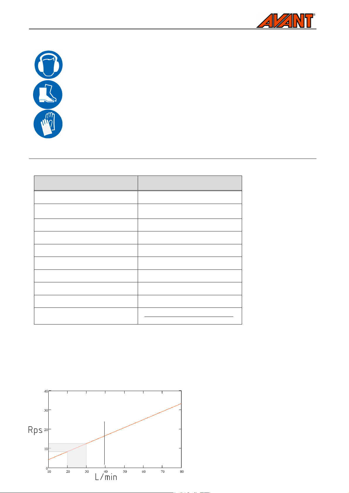
Graph 1 – Rotating speed of Cutter bar mower according to hydraulic oil flow and
Remember to wear proper protective clothing:
■ The noise level at the driver's seat may exceed 85 dB(A). Wear hearing protection
while working with the loader.
■ Wear safety boots while working with the loader.
■ Wear protective gloves and safety goggles when handling hydraulic components.
Wear protective gloves when handling the blades of the attachment.
4. Technical specifications
Table 2 – Avant Cutter bar mower – technical specifications
Product number
:
A35676
A35790
Working width: 1400 mm
Side reach:
(from middle of quick attach plate)
Reach drawing: See Chapter 6.2
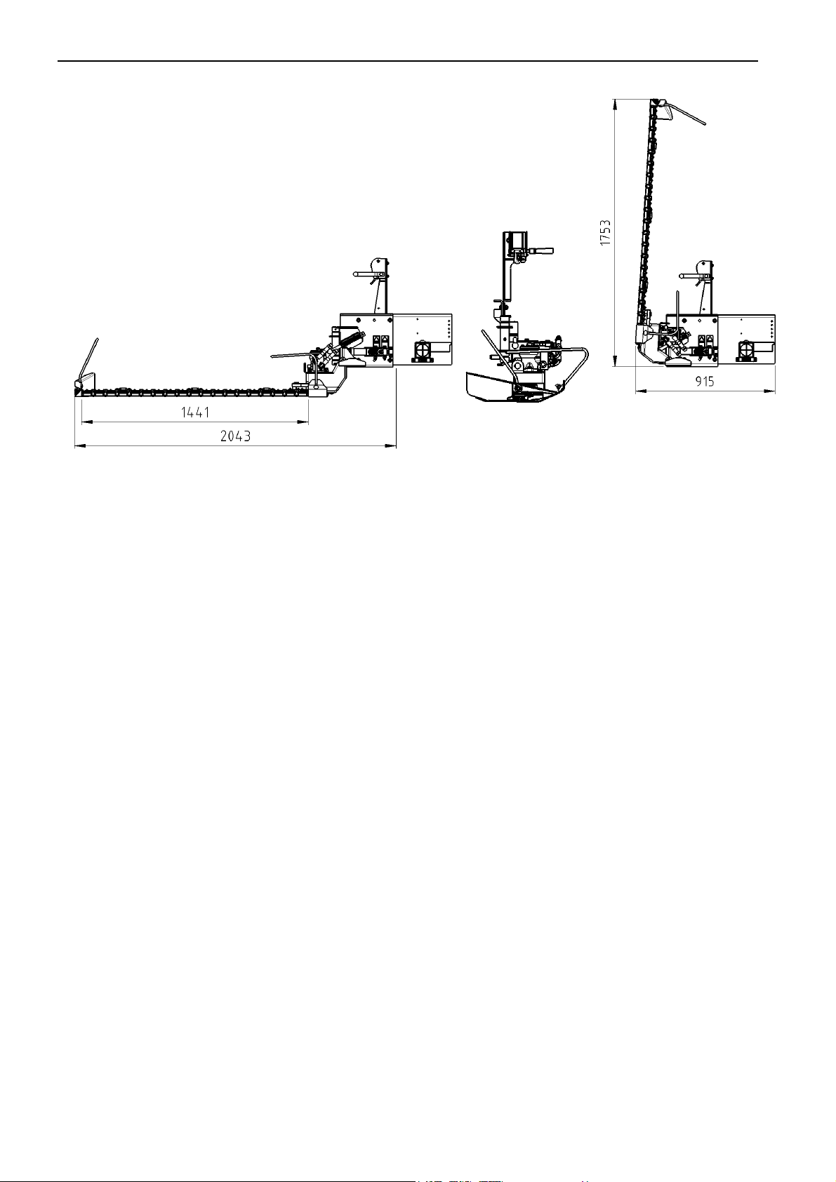
Dimensions: See Page 2
Weight: 70 kg
Blade bar: 19 pcs 65810, teethed
Nominal hydraulic flow: 20-30 l/min
Maximum recommended hydraulic flow: 40 l/min
Maximum operating pressure: 22,5 MPa (225 bar)
Suitable AVANT loader:
2040 mm
A35676 300-700 series
A35790 200-series
Available options:
■ Electric blade bar control A35975
■ Long hay mowing kit A416962
Ask for the availability of the options from your dealer. For installation services, refer to service point as
needed.
recommended operating speed
Page 9
9(22)
A46771
A46772
Table 3 – Main components of Cutter bar mower
A46803
A46749
Attachment ID plate
4.1. Safety labels and main components
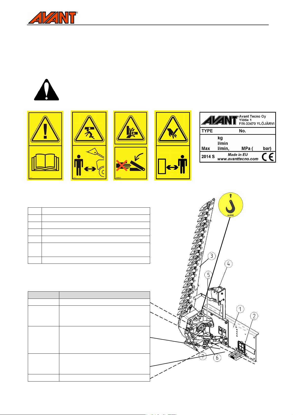
Listed below are the labels and markings, which must be visible on the equipment. Replace the warning
labels, if they have become unclear or detached completely. New labels are available via your retailer or
contact information provided on the cover.
The warning labels contain important safety information and they help to identify and
remember the hazards related to the equipment. Replace any damaged or missing
warning label with a new one.
1 Frame with Avant quick coupling plate
2 Multiconnector parking stand
3 Blade bar, 19 blades
4 Blade bar lowering winch
5 Blade bar upper position spring retainer
6 Spring release mechanism and compression
spring
7 Storage support
Table 4 – Decal warning messages and locations
Decal Message
A46771 Read instructions before use.
A46772 Do not go under a raised attachment
or the loader boom, keep a safe
distance from lifted equipment.
A46803 Crushing hazard, moving blade bar
and joint. Lower the blade bar with
controlled motion and keep hands and
feet away from hazard areas.
A46709 Severing hazard, sharp and strong
blades. Follow safe stopping
procedure.
Identification plate of the attachment
Page 10
10(22)
5. Assembly of the Cutter bar mower
The attachment is ready for use as delivered. Attach the attachment and its hydraulic hoses to the loader as
instructed below.
5.1. Coupling the attachment to the loader
Coupling the attachment to the loader is quick and easy, but it must be done carefully. The attachment is fixed
to the loader boom by using the quick attach plate and the counterpart on the attachment. If the attachment is
not locked to the loader, it may detach from the loader and cause hazardous situations. In the worst case, the
attachment may slide towards the driver along a raised boom. For this reason, the attachment must not be
raised over one metre under any circumstance if it has not been locked. To prevent hazardous situations,
always follow the attachment coupling instructions provided in the following pages. Also remember the safety
instructions shown in Chapter 3 and additional infromation shown in the operator’s manual of the loader. The
attachment is mounted to the loader as follows:
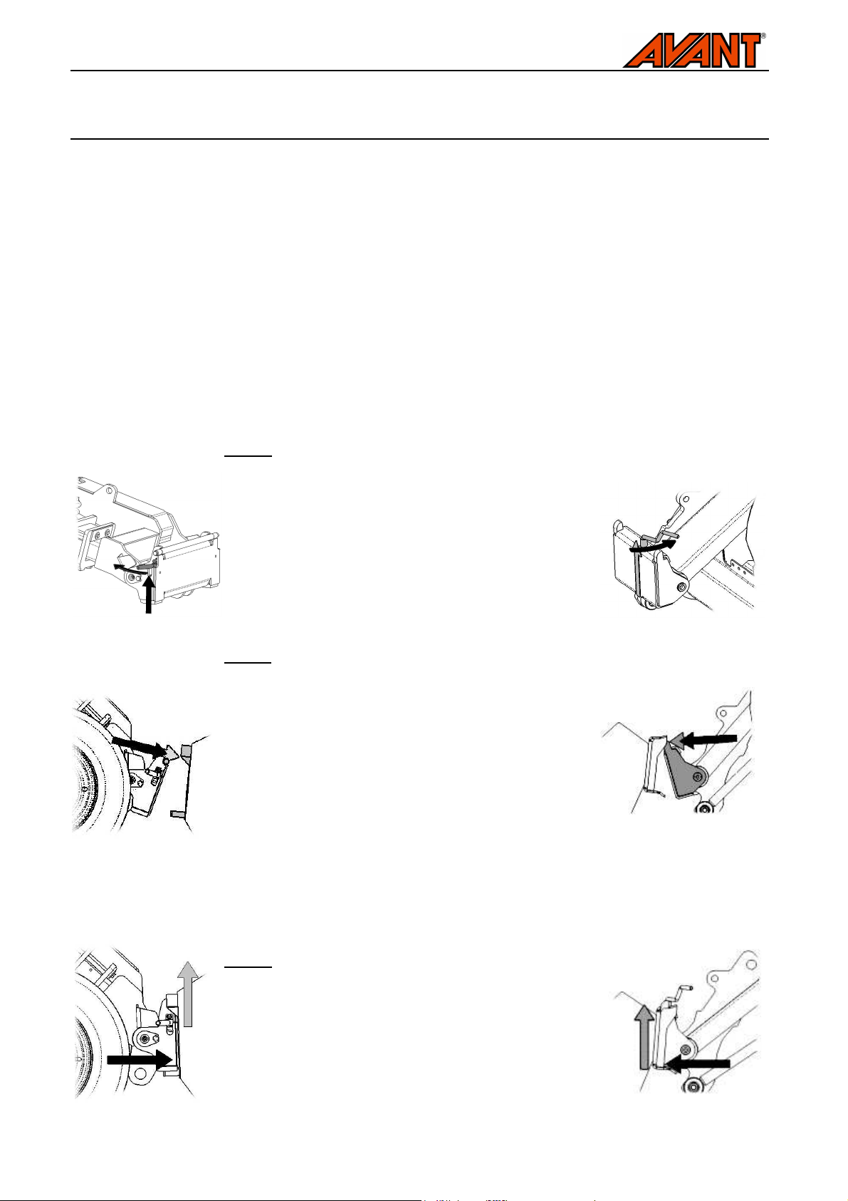
300-700 series loaders:
Step 1:
• Lift the quick attach plate locking pin / locking pins up
and turn them backwards into the slot so that they are
locked in the upper position.
• If your loader is equipped with a hydraulic attachment
locking system, see additional instructions about the
use of the locking system from the relevant manuals.
• Ensure that the hydraulic hoses are not in the way
during installation.
Step 2:
• Turn the quick attach plate hydraulically to an obliquely
forward position.
• Drive the loader onto the attachment. If your loader is
equipped with a telescopic boom, you can utilise this.
Align the upper pins of the loader’s quick coupling
plate so that they are under the corresponding
brackets of the attachment.
• Depending on the storage position of the mower and
the reach capability of the loader, it may be necessary
to assist the mounting of the attachment manually. See
Chapter 5.4 for correct uncoupling procedure and
storage position.
200 series loaders:
Step 3:
• Lift the boom slightly – pull the boom control lever
backward to raise the attachment off the ground.
• Turn the boom control lever left to turn the bottom
section of the quick attach plate onto the attachment.
• Lock the locking pins manually or lock the hydraulic
locking. Always check the locking of pin / pins.
Page 11
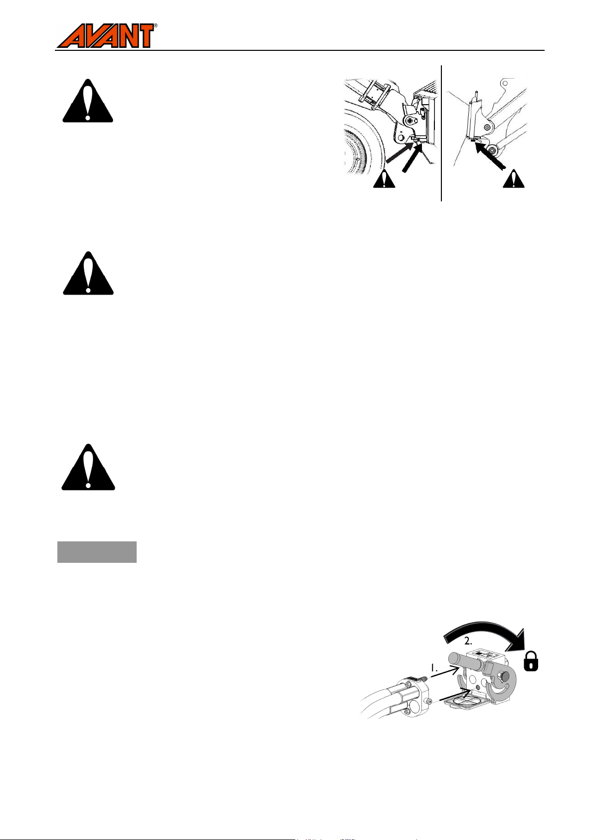
An attachment that has not been completely
locked to the loader may fall or tip over on the
boom or operator, or under the loader during
driving, causing loss of control of the loader.
Before moving or lifting the attachment, make
sure that the locking pins are in the lower
position and come through the fasteners on
the attachment on both sides. Never move or
lift an attachment that has not been locked.
Excessive tilting or lifting of an unlocked attachment increases the risk of tipping the
attachment over. Do not use the automatic locking of the locking pins when the
attachment is lifted more than one metre from the ground. If the locking pins do not
return to the normal position when tilting, do not tilt or raise the attachment any more.
Lower the attachment on the ground and secure the locking manually.
300-700 series loaders 200 series loaders
11(22)
5.2. Connecting and disconnecting the hydraulic fittings
On 300-700 series loaders hydraulic hoses are connected using the multi connector system. If you want to
change the type of the hydraulic couplings, contact your Avant dealer or service point for instructions or
installation services. On 200-series loaders only conventional quick couplings are available.
Never connect or disconnect quick couplings or other hydraulic components while the
system is under pressure or if the control lever of the auxiliary hydraulics control lever is
locked on. Connecting or disconnecting the hydraulic couplings while the system is
pressurized may lead to unintended movements of the attachment, or ejection of highpressure fluid, which can cause serious injuries or burns.
Keep all fittings as clean as possible; use the protective caps for the quick
NOTICE
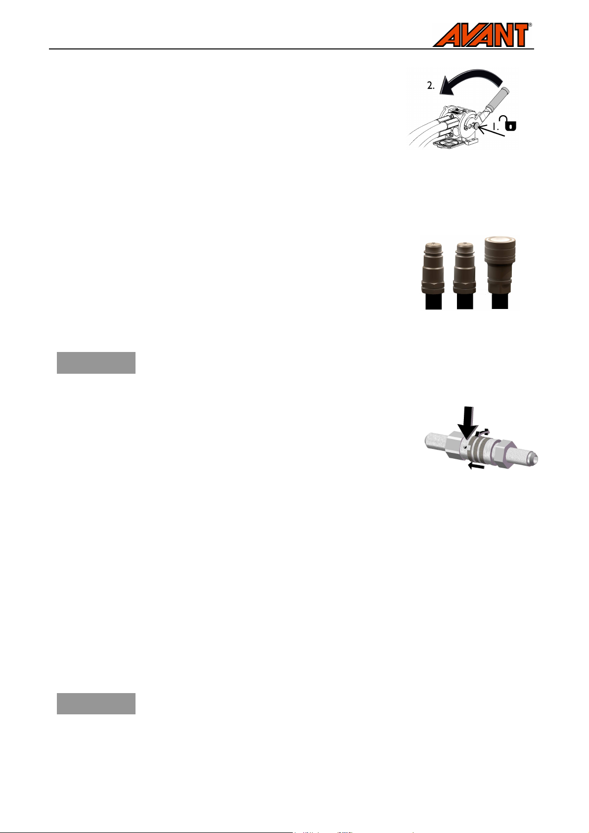
Connecting the multi connector system:
1.
Align the pins of the attachment connector with
corresponding holes of the loader connector. The multi
connector will not connect if the attachment connector is
upside down.
2.
Connect and lock the multiconnector by turning the lever
towards the loader.
couplings on both the attachment and the loader. Dirt, ice, etc. may make using
the fittings significantly more difficult. Never leave the hoses hanging on the
ground; place them on top of the equipment.
The lever should move easily all the way to its locking position. If the lever does not slide smoothly, check the
alignment and position of the connector and clean the connectors. Also shut down the loader and release the
residual hydraulic pressure.
Page 12
12(22)
To disconnect the multi connector system, turn off the auxiliary hydraulics
of the loader, and:
1.
Push the knob on the side of the connector to unlock.
2.
Turn the lever to disconnect.
Conventional quick couplings
Before connecting or disconnecting the standard quick couplings, the residual pressure must be released as
shown below. The conventional quick couplings will not connect, if there is pressure in the hydraulic system.
To connect and disconnect the standard couplings, move the collar at the end of
the female fitting. The hoses should be connected so that the fitting equipped
with a coloured cap is connected to the corresponding fitting of the loader. Note
that the protective caps on the loader and the attachment can be fastened to
each other during operation to reduce the accumulation of dirt. When
disconnecting the standard quick couplings a small amount of oil may drip from
the couplings. Wear protective gloves and have some cloth at hand to keep the
equipment clean.
NOTICE
In a 200-series machine, the hose can be connected by pushing the fitting in the
counterpart. When connecting and disconnecting the 200-series hydraulics quick
couplings, you should pay attention to their locking. There is a small groove in
the collar of all female fittings, and a small ball near the collar. When connecting
or disconnecting, the groove and ball must be aligned. The locking prevents the
female and male fittings from being disconnected from each other by accident
when the attachment moves. The collar may also turn accidentally to the locking
position, making it impossible to connect or disconnect the couplings.
Make sure that all three couplings are properly connected, otherwise the hydraulic
motor of the mower may get damaged.
(alternative couplings for some loader models):
Releasing residual hydraulic pressure:
To make sure that there will not be residual pressure in the hydraulic system of the attachment, shut down the
loader engine and move the auxiliary hydraulics control lever of the loader to it’s extreme positions before
disconnecting the couplings. If the fittings will not connect to the loader, the residual pressure must be
released. The residual pressure must be released before handling the blades of the attachment and before
storage of the attachment.
Disconnecting the hydraulics:
Before disconnecting the fittings, place the attachment on solid and level surface, as described in chapter 5.4.
Follow safe stopping procedure.
NOTICE
Always disconnect the hydraulic fittings first before unlocking the quick attach
plate, to prevent hose damage and any oil spills. Reinstall the protective caps on
the fittings to prevent dirt from entering the hydraulic system.
Page 13
13(22)
5.3. Electrical connection, electric blade bar control (optional equipment)
The mower can be equipped with an electric actuator, that replaces the manual winch for lowering the blade
bar. In this case, the electric harness of the attachment must be connected to the loader. There are two
options for the electrical connection:
■ Electric blade bar lowering can be controlled with the attachment control switch pack, that is
available as an option to 400-700 series loaders. When using the switch pack, the electric cable
of the loader is connected to a plug near the hydraulic fittings.
■ Alternatively, a cable harness A35358 equipped with a 2-way switch, that is delivered with the
mower, can be used. Instructions concerning the loader plug are provided in the loader manual.
Select the location of the switch in the cab to ensure that it is easily accessible but will not be
used inadvertently.
Route the selected cable in a way that it cannot get stuck on anything or stretch when the equipment moves.
With the help of the attachment control switch pack available for the loader, the attachment control switches
are easily accessible at the end of the boom control lever. See instructions about using the electric actuator in
chapter 6.2.
5.4. Uncoupling the attachment and storage
Storage place that is protected from rain and direct sun is the best for an attachment. Uncouple the
attachment only on level and firm surface, which can support the weight of the attachment steadily. To avoid
storing the attachment directly on the ground for long periods of time to avoid damage from corrosion, place
the attachment on a pallet, for example.
NOTICE
Correct storage position:
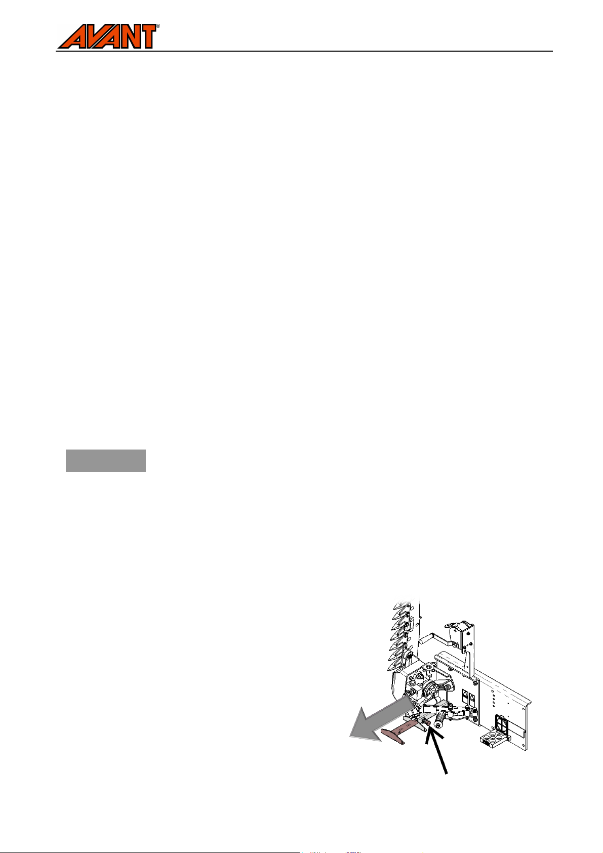
At the front of the mower, there is a support stand, which must be extended to prevent the mower from tipping
forward.
Uncoupling the mower:
1. Select a level and firm storage area that can
support the mower standing upright.
2. Stop the attachment following the safe stopping
procedure. Uncouple hydraulic fittings and electric
harness.
3. Fit blade cover.
4. Turn the blade bar up against the retainer spring.
5. Extend and lock the support stand shown in
adjacent figure.
6. Lower the attachment completely down in upright
position and unlock locking pins. Tilt the quick
coupling plate carefully and manoeuvre the loader
away.
Avoid storing the attachment directly on the ground for long periods of time to
avoid damage from corrosion. Clean and service the attachment before long
storage periods as shown in chapter 7.
Page 14
14(22)
Blade cover fitted
A loader that is not equipped with a telescopic boom:
If the loader is not equipped with a telescopic boom, and the mower is stored directly against the ground, the
loader may not reach the brackets of the mower’s quick coupling plate. In this case, a separate lift can be
used, or the mower can be tilted slightly manually holding from its blade bar, so that the quick coupling
brackets will set above the loader’s coupling plate. Before handling the mower manually, drive the loader as
close to the quick attach plate of the mower as possible, and tilt the attachment plate of the loader forward to
minimise the needed manual tilting.
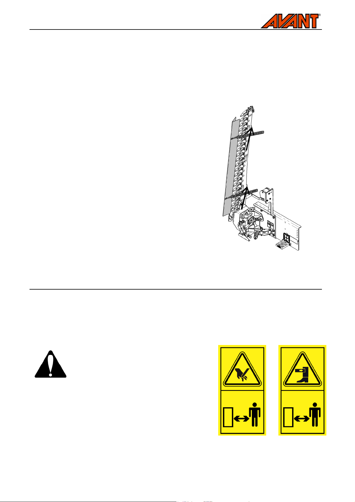
Blade cover:
The blade cover protects both the attachment and any
person near the attachment. Always fit the blade cover
after use and do not remove until work can be started.
Clean the blade before storage. Allow the blade to dry
before fitting the cover, if storing for longer periods of
time.
6. Instructions for use
Check the attachment and the operating area once more before starting to work. Quick inspection of the
mower before starting to use it is part of ensuring safety and the best performance of the equipment. Practise
the use of the mower and its controls in an open and safe area. If you are unfamiliar with the loader to be
used, it is recommended to practice its use without any attachments.
Beware of the sharp and strong blade bar. Start
the mower only after it has been set to working
position and work can be started. Always stop
the attachment before leaving the driver’s seat
and keep a safe distance to others. Follow safe
stopping procedure always when it is
necessary to go near the blades or when
handling the blade bar, i.e. cleaning, height
adjustment, or uncoupling the attachment.
Always fit the blade cover when the attachment
is not in use.
Page 15
15(22)
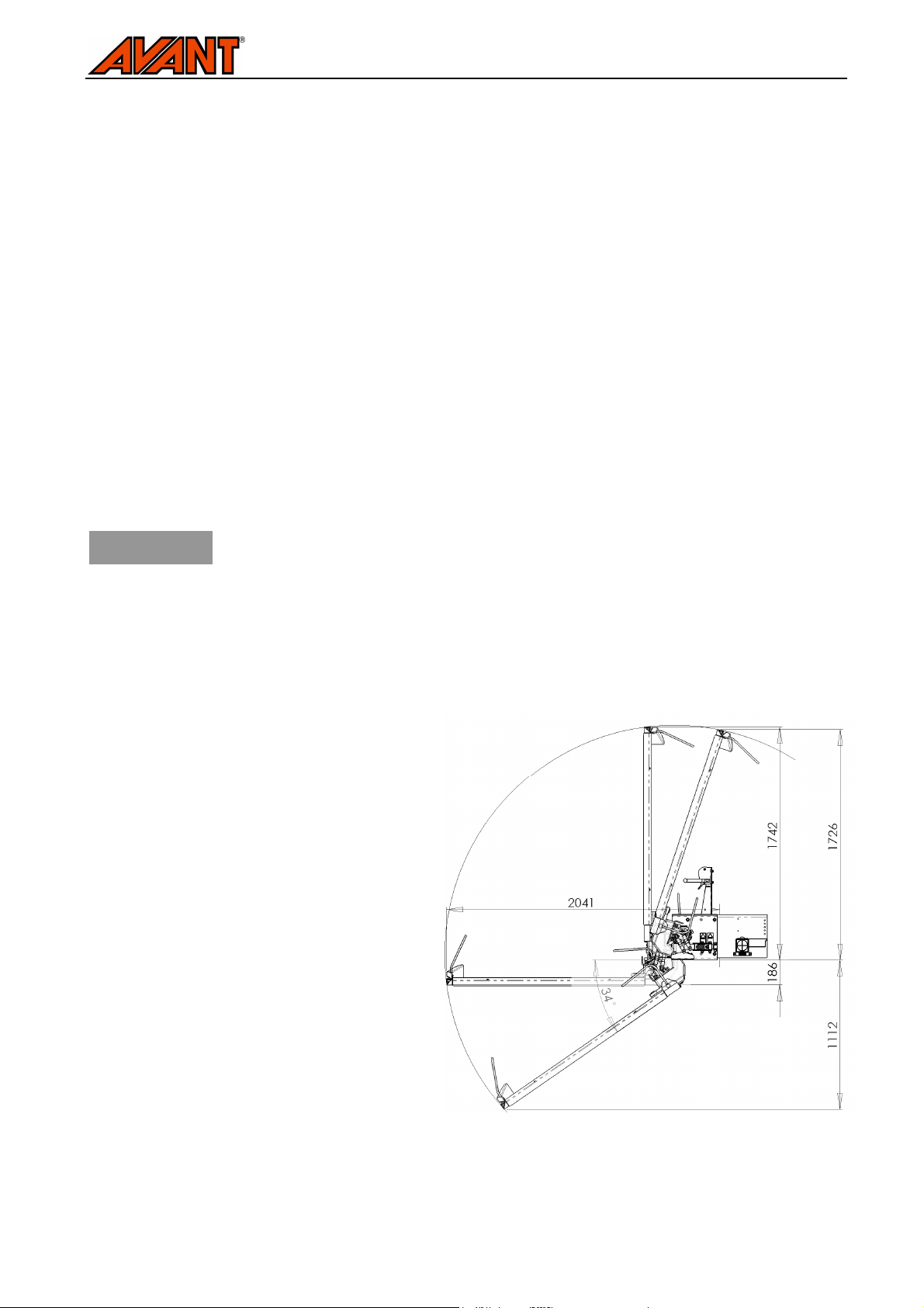
Reach diagram of the blade bar
6.1. Checks before use
■ Check the general condition of the attachment and the loader, and check for possible hydraulic oil
leaks. The attachment must not be used, if there is a fault in the hydraulic system of the loader or the
attachment.
■ Ensure that the loader and the attachment are used in a safe and intended manner. Before starting
mowing, check the operating area and remove or mark objets affecting the safety of mowing or the
stability of the loader. Remember correct working methods and avoid leaving the driver’s seat
unnecessarily.
■ Check the condition of the blade lowering wire, so that the blade bar will remain in its intended
position. Do not use the machine if the blade bar is lowered against the ground.
■ Check that the blade bar is intact and clean. Remove any trash stuck on the blade bar. Check visually
that the blades are intact and can move freely.
■ Check that the blade bar is in its normal perpendicular operating position supported by its spring
release mechanism, and has not tilted backwards. See instructions about the blade spring release
mechanism from chapter 6.3.
■ Operate the attachment or any controls only when sitting on the driver's seat.
NOTICE
The loader should be equipped with a hydraulic oil cooler when using the mower.
Overheating of the oil decreases performance and affects the service life of the
hydraulic components of both the attachment and the loader. Regularly clean the
loader oil cooler core; refer to the loader manual for more instructions.
6.2. Operating the mower
Working position and reach of blade bar:
The blade can be set according to operating
area as shown in adjacent figure. In near
vertical positions a spring retainer will hold the
blade in desired position, preventing swinging
of the blade.
The blade bar should be set to near the
surface of the ground, but not completely
leaning on the ground. The lifting cable must
be connected and tensioned when mower is
in use.
Page 16
16(22)
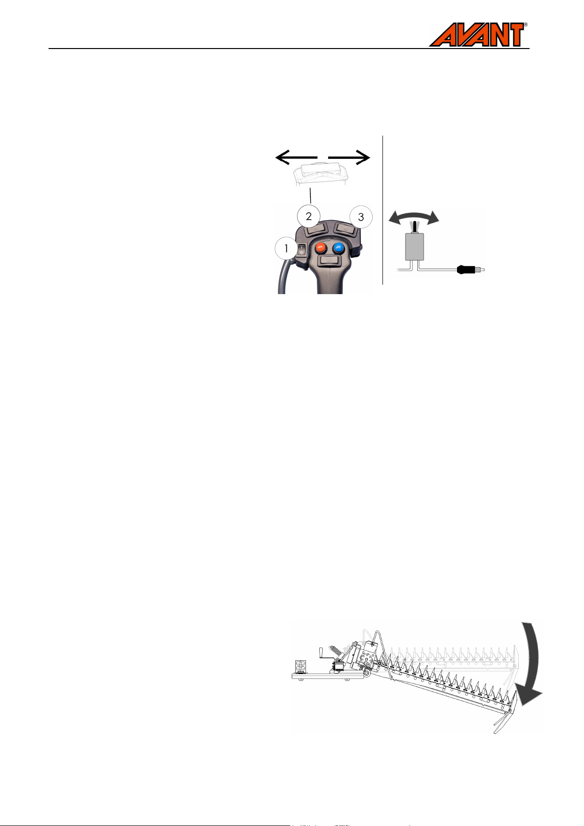
Electric lowering of blade bar
Connects to electric socket
near the driver’s seat
Movement of the blade bar, spring release system
Turning the blade bar to operating position:
■ Before handling the manual winch, stop the attachment following safe stopping procedure. Lower
the blade bar with controlled motion, holding the winch handle throughout lowering.
■ When using the electric blade bar
lowering, the actuator is controlled
with switch number 2 of the
attachment control switch pack, or
by using the 2-way switch
delivered with the attachment.
Starting the mower:
The mower is started by turning the auxiliary hydraulics control lever of the loader to its locking position.
Correct running speed of the loader engine depends on operating conditions and driving speed. The mower
can cut also when it runs slowly, but for the best results, the loader should generate hydraulic oil flow of about
20-30 l/min. On most loaders this is achieved when the loader engine is run at about half of the maximum
rpm, using one hydraulic pump. If needed, check the hydraulic oil output of the loader from the operator’s
manual of the loader.
During operation:
Operating on inclined terrain and slopes requires extra caution. Watch for holes, bumps, rocks and other
possible obstacles, that may be poorly visible. Uneven terrain may tip over the loader. Use low speed on
slopes and do not make sudden changes in speed or direction. Try to drive straight up or down a hill, not
across, to avoid excessive side tilting. If the loader stops while driving up a steep slope, first stop the
attachment and then reverse a little. Keep the articulation of the loader frame in as straight position as
possible. Be careful when operating near ditches or embankments as the machine could slide or turn over if
an edge caves in. Do not lift the attachment high on inclined terrain.
6.3. Blade bar spring release system
To protect the attachment and the operator the blade bar will swing back if the blade bar hits an obstacle. The
system will not protect the mower or it’s blades against overload, and the attachment may get damaged
regardless of the release system.
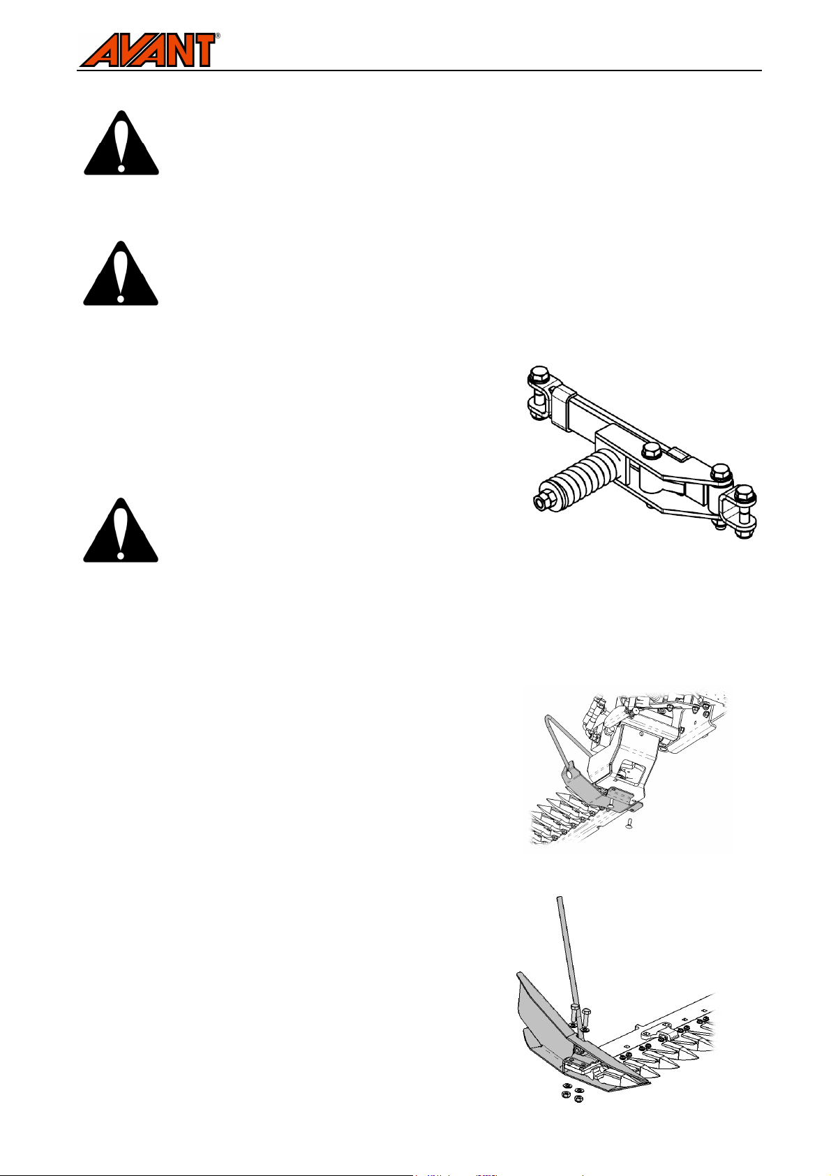
The spring release system should work so that it
will allow the blade bar to tilt back when moderate
force is applied to the tip of the blade bar.
When the spring release system allows the blade
bar to tilt back, stop the loader immediately and
stop also the attachment. The blade bar can be
turned back to operating position by operating the
loader boom, or by turning it back manually.
Remember to follow safe stopping procedure
before going near the blades.
Page 17
The spring release system does not replace careful and cautious driving style, and the
Spring release mechanism of the blade bar
Long hay mowing kit, base of the blade bar
Long hay mowing kit, tip of the blade bar
system can’t fully remove hazards related to sudden stopping of the machine. Always
use seat belt and drive slowly, and remove or mark any obstacle in the operating area so
that collisions can be avoided.
Operate the mower only when the blade bar is in its normal operating position retained
by the spring release mechanism, perpendicular to the driving direction. Check the
operation of the spring release system regularly. Blocking the release system completely
will expose the operator to hazards related to sudden stopping of the loader, make sure
that the system is in proper working condition.
If the system does not work as desired, allowing the blade bar to
turn too easily, it can be adjusted by tensioning its spring. The
system should be kept clean. Some oil can be sprayed in
between the sliding surfaces. Normally, the system shouldn’t
give in when pulling the blade bar manually
17(22)
The spring of the release system is under
compression tension. Careless handling of the
system or its spring can cause the spring to be
thrown. Leave the outer spring retaining nut in
its place.
6.4. Long hay mowing kit (optional equipment)
When cutting long hay, the mower can be equipped with long
hay mowing kit, which reduces entangling of hay onto the blade
bar, and will guide the clippings for more even performance. The
kit also protects the end of the blade bar, making it
recommendable to install the kit whenever the blade may hit the
ground often.
Long hay mowing kit includes guide/skid sets that are installed
on both ends of the blade bar.
Page 18
18(22)
7. Maintenance and servicing
The attachment has been designed to be as maintenance free as possible. Continuous maintenance of the
mower includes careful cleaning and regular lubrication. Also, the condition of the hydraulic hoses and
components must be monitored regularly. Because of the crushing hazard caused by the loader boom and the
severing hazard of powerful cutting blades, all maintenance procedures must be made when the attachment is
lowered completely against the ground and when the residual pressure of the hydraulic system has been
released. For the best stability of the mower, it should be kept locked on the loader during maintenance.
Spare parts are available from your nearest AVANT representative. Please contact your nearest Avant dealer
if you have any additional questions, or if you need any maintenance services.
Ensure that the attachment is properly supported also when it is connected to the loader.
All maintenance procedures must be performed while the attachment is lowered on the
ground, the loader engine is shut down and the residual pressure is released. The loader
boom may lower by itself causing crushing hazard.
Before handling the blades, the attachment must be stopped folloeing the safe stopping
procedure, so that the blades can’t unexpectedly make cutting movement. Also, wear
protective gloves when handling sharp blades.
7.1. Inspecting hydraulic components
Check the condition of the hydraulic hoses and components when the engine has been turned off and the
pressure has been relieved. Do not use the equipment, if you have discovered a leak in the hydraulic system
of the attachment or the loader. Leaking hydraulic fluid may penetrate skin and cause serious injuries. Seek
medical attention immediately in case hydraulic fluid penetrates the skin. Wash any part of body that has been
in contact with hydraulic oil carefully with water and soap. Hydraulic fluid is also harmful to the environment
and any leak to the environment must be prevented. Repair all leaks immediately after detecting them; a small
leak can quickly grow into a big one. Operate the attachment only with type of hydraulic oil that is accepted for
use in Avant loaders.
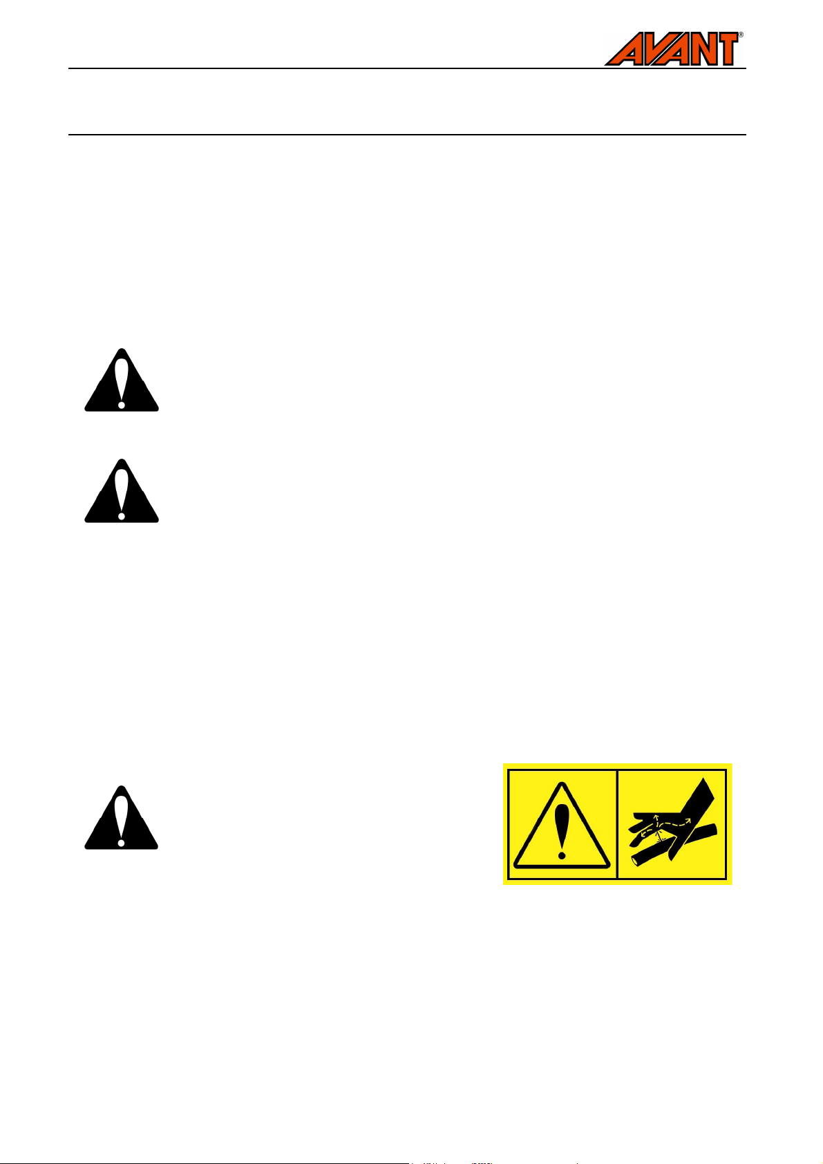
Never handle hydraulic components when the
hydraulic system is pressurized, since a fitting
may break or become loose and the released oil
may cause serious injuries. Do not use the
equipment, if you have discovered a fault in the
hydraulic system.
Check hoses visually for cracks or abrasions. If there are signs of leaks, to check a component, hold up a
piece of cardboard in the area where a leak is suspected. Do not use hands to search for leaks. Monitor the
wearing of the hoses and stop the use, if the surface layer of any hose has worn off. Check the routing of the
hoses; adjust the hose clamps to avoid abrasion to the hoses. The hoses have limited service life, which is
marked on the hoses. After the date marked on the hoses, they should be replaced with new ones.
Page 19
19(22)
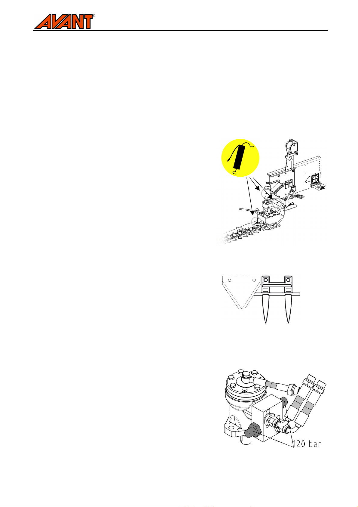
Blade 65810 and blade guide
Pressure relief adjustment of hydraulic
Finding any fault means that the hydraulic hose or component must be replaced and the equipment must not
be used until it is repaired. Spare parts are available from your nearest AVANT retailer or authorized service
point. Leave the repair work to professional service technicians, if you don’t have adequate knowledge and
experience about hydraulic assemblies and how to perform the repairing safely.
7.2. Cleaning and lubrication
Clean the attachment regularly. Pressure washer and mild detergent can be used. Spraying on hydraulic or
electric components or the labels on the attachment should be avoided. Also avoid spraying directly on the
winch cable. Allow the machine to dry and lubricate before fitting the blade cover.
Before long storage periods touch up paint where needed, add
grease the lubricating points and apply thin oil on the blade bar
to prevent rust damage. There are a total of three lubricating
points, located in vertical joint of the blade bar, hinge of the
spring release system, and at the bearing of the blade moving
rod, on top of the blade bar. Lubricant should be added to the
bearing after every 8 hours of use, and less frequently to the
hinges. The hydraulic motor end of the rod is maintenance free.
The winch gears may be oiled lightly as needed, but applying oil
or grease on the cable should be avoided, as it would cause the
cable to collect dirt shortening its service life. The electric
actuator system is maintenance free.
7.3. Mower blades
There are a total of 19 blades number 65810, whose teethed
edges help to retain good cutting properties over a long time.
Damaged blades can be replaced, and also blade guides should
be checked and replaced as necessary. The blades must slide
smoothly slong the blade guides, and if a blade or guide gets
damaged, they must be replaced before continuing use.
7.4. Hydraulic motor settings
To protect the blades, the hydraulic motor is assembled with a
pressure relief valve, set at 120 bar. If needed, the pressure can
be checked and adjusted. Original value must not be exceeded.
motor
Page 20

20(22)
8. Warranty terms
Avant Tecno Oy grants a warranty of one year (12 months) from the date of purchase for the attachment it manufactures.
The warranty covers repair costs as follows:
• Work costs are covered, if the repair is not performed at the factory.
• The factory replaces any defective components or consumables.
The factory may reimburse the price of components purchased by the customer in special cases that have been agreed in
advance.
The warranty does not cover:
• Normal maintenance work or parts and consumables required for it.
• Damages caused by unusual operating conditions or ways of use, negligence, structural changes made without the
consent of Avant Tecno Oy, use of non-original parts or lack of maintenance.
• Consequences of a defect, such as interruption of work or other possible additional damages.
• Travel and/or freight costs caused by the repair.
Page 21
Cutter Bar Mower 2014 1
EY-vaatimustenmukaisuusvakuutus
EG-försäkran om överensstämmelse
EU samsvarserklæring
EF-overensstemmelseserklæring
EC Declaration of Conformity
EG-Konformitätserklärung
Déclaration de conformité CE
Valmistaja / Tillverkare / Produsent / Producent / Manufacturer / Hersteller / Fabricant: AVANT TECNO OY
Osoite / Adress / Adresse / Address / Adresse: Ylötie 1
33470 YLÖJÄRVI
FINLAND
Vakuutamme täten, että alla mainitut tuotteet täyttävät konedirektiivin turvallisuus- ja terveysvaatimukset (direktiivi
2006/42/EY muutoksineen). Seuraavia yhdenmukaistettuja standardeja on sovellettu /
Vi försäkrar härmed att nedan beskrivna produkter överensstämmer med hälso- och säkerhetskrav i EG-maskindirektiv
(EG-direktiv 2006/42/EG som ändrat). Följande harmoniserade standarder har tillämpats /
Vi erklærer herved at produktet som er oppgitt under er i samsvar med forskriftene i Maskindirektivet (direktiv
2006/42/EC med endringer). Følgende harmoniserte standarder har blitt anvendt /
Vi erklærer herved, at nedenstående produkter er i overensstemmelse med bestemmelserne i maskindirektivet (direktiv
2006/42/EF indeholdende ændringer). Følgende harmoniserede standarder er anvendt /
We hereby declare that the products listed below are in conformity with the provisions of the Machinery Directive
(directive 2006/42/EC as amended). The following harmonized standards have been applied /
Wir erklären hiermit, dass die nachstehend aufgeführte Maschine konform ist mit den Bestimmungen der EGMaschinenrichtlinie (EG-Richtlinie 2006/42/EG mit Änderungen). Die folgende harmonisierte Normen wurden
angewandt/
Nous déclarons par la présente que les produits mentionnés ci-dessous sont conformes aux exigences en matière de
sécurité et de santé de la directive relative aux machines (directive 2006/42/CE, avec ses modifications) Les normes
harmonisées suivantes ont été appliquées :
SFS-EN ISO 12100, SFS-EN ISO 4413
Kuvaus / Beskrivning / Beskrivelse / Beskrivelse / Description / Beschreibung / Description :
Hydraulitoiminen palkkiniittokone; Avant-kuormaajan työlaite
Hydraulisk slåtterbalk; arbetsredskap för Avant lastare
Hydraulisk fingerslåmaskin; redskap for Avant minilastere
Hydraulisk fingerklipper redskab til Avant Minilæssere
Hydraulic Cutter bar mower; attachment for Avant loaders
Hydraulische Balkenmähwerk; Anbaugerät für Avant Radlader
Barre de coupe a doigts à commande hydraulique destinée à être utilisée avec les chargeurs Avant
Mallit / Modeller / Modeller / Modeller / Models / Modellen / Modèles:
313S, 320S, 320S+, 419, 420,
Avant 216, 218, 220
Palkkiniittokone
Slåtterbalk
Fingerslåmaskin
Fingerklipper
Cutter bar mower
Balkenmähwerk
Barre de coupe a doigts
____________________1.9.2014 Ylöjärvi, Finland
A35790 A35676
520, 525LPG, R28, 528, 630,
635, 635, 640, 745, 750, 760
Risto Käkelä,
Toimitusjohtaja / Verkställande direktör / Administrerende direktør /
Managing Director / Geschäftsführer / Directeur général
Avant Tecno Oy 2014 Copyright all rights reserved
Page 22
Avant Tecno Oy 2014 Copyright all rights reserved
 Loading...