


4 in 1 Bucket 2016 2
Product number
Straight edge
With teeth
1100 mm
A21245
A21249
1280 mm
A21156
A21184
1400 mm
A21266
A21269
English
www.avanttecno.com
Operator's Manual for Attachment
4 in 1 Bucket

4 in 1 Bucket 2016 2

4 in 1 Bucket 2016 2
CONTENTS
1. FOREWORD ........................................................................................................................................ 4
2. DESIGNED PURPOSE OF USE.......................................................................................................... 5
3. SAFETY INSTRUCTIONS FOR USING THE ATTACHMENT ...................................................... 6
4. TECHNICAL SPECIFICATIONS ....................................................................................................... 9
4.1 Safety labels and main components of the attachment .................................................................................... 9
5. ATTACHING THE ATTACHMENT ................................................................................................. 11
5.1.1 Connecting and disconnecting the hydraulic hoses .................................................................................. 12
6. INSTRUCTIONS FOR USE ................................................................................................................ 14
6.1 Checks before use ..................................................................................................................................................... 14
6.2 Using a bucket ............................................................................................................................................................. 15
6.3 Material handling ......................................................................................................................................................... 17
6.4 Operating on inclined terrain .................................................................................................................................. 18
6.4.1 Operation with the tilt adapter ...................................................................................................................... 18
7. MAINTENANCE AND SERVICE ....................................................................................................... 19
7.1 Checking hydraulic components ............................................................................................................................ 19
7.2 Cleaning the attachment ........................................................................................................................................... 19
7.3 Checking metal structures ....................................................................................................................................... 20
7.4 Lubrication ................................................................................................................................................................... 20
8. WARRANTY TERMS .......................................................................................................................... 20

4 (22)
WARNING:
This safety symbol refers to important safety information in this manual.
It warns of an immediate hazard that could cause serious personal
injury.
Read the warning text accompanying the symbol carefully and ensure
that other operators are also familiar with the warnings, since personal
safety is at stake.
This signal word indicates information about the correct operation and maintenance
of the equipment.
Failure to observe the instructions accompanying the symbol can lead to equipment
breakdown or other property damage.
1. Foreword
Avant Tecno Oy would like to thank you for your purchase of this attachment for your Avant loader. It has
been designed and manufactured on the basis of years of experience on product development and
manufacturing. By familiarising yourself with this manual and following the instructions, you ascertain your
safety and ensure the reliable operation and long service life of the equipment. Read the instructions carefully
before starting to use the equipment or performing maintenance.
The purpose of this manual is to help you to:
operate the equipment in a safe and efficient manner
observe and prevent any hazardous situations
keep the equipment intact and ensure a long service life
The following warning symbols are used throughout this manual to indicate factors that must be taken into
account to reduce the risk of personal injury or damage to property:
With these instructions, even an inexperienced user can use the attachment and loader safely. The manual
includes important instructions for experienced AVANT operators as well. Ensure that all persons using the
loader have received proper guidance and familiarised themselves with the manual of the loader, each
attachment that are used, and all safety instructions before using the equipment. Using the equipment for
other purposes or use in any other way than described in this manual is prohibited. Keep this manual at hand
throughout the service life of the equipment. If you sell or transfer the equipment, be sure to hand over this
manual to the new owner. If the manual is lost or damaged, you can request a new one from your Avant
dealer or from the manufacturer. Due to continuous product development some of the details shown in this
manual may differ from your equipment. This manual contains the original instructions in English.
In addition to the safety instructions included in this manual, you must observe all occupational safety
regulations, local laws, and other regulations concerning the use of the equipment. Particularly the regulations
concerning the use of the equipment on public road areas must be observed. We reserve the right to change
the contents of the manual without notification.

5 (22)
Avant
216
218
220
220
series 2
225
225LPG
313S
320S
320S+
419
420
520
R20
525LPG
R28
528
630
R35
635
640
745
750
760i
A21245
A21249
1100 mm
-
-
-
A21156
A21184
1280 mm
-
-
A21266
A21269
1400 mm
- - -
2. Designed purpose of use
The AVANT 4 in 1 buckets are attachments designed and manufactured to suite AVANT multi purpose
loaders shown in Table 1. They are versatile buckets for earth-moving tasks, material handling, levelling and
snow clearing work. The 4 in 1 bucket is equipped with two hydraulic cylinders which open the bucket, making
it possible to use the bucket very efficiently as a dozer blade, leveller or as a grab to pick rocks etc. The
opening feature can also be utilized for emptying the bucket at a higher level. The buckets are available with
straight edge or with teeth.
Various width options are available to best suite each task and loader model. When choosing a bucket, the
intended use of the bucket,and the model of the loader should be considered, as shown in Table 1. If the
loader is fitted with other than standard tyres, or differs from original specifications, consult your Avant dealer
to choose the best bucket.
The attachment has been designed to require as little maintenance as possible. The operator can perform
regular maintenance tasks. All repair work can’t be performed by the operator, and demanding repair and
maintenance operations are to be left for professional maintenance. All maintenance work must be done using
proper safety equipment. Spare parts must be identical with original specifications, which can be ensured by
using only original spare parts. A separate spare parts catalog may be available, consult your Avant dealer.
Familiarise yourself with the manual's instructions regarding service and maintenance. Please contact your
AVANT retailer if you have additional questions about the operation or maintenance of the equipment, or if
you require spare parts or maintenance services.
Compatibility with Avant Loaders
Compatibility recommendations are based on the width of the loader and available lifting capacity. Do not use
too wide bucket when handling heavy loads, as the actual breakout force (bucket tilting capacity) decreases
with wide buckets and the overall performance will decrease. To estimate the lifting capacity of the loader the
Table 5 can be used together with the load diagram shown in the operator’s manual of the loader. When using
with models marked with (), full performance may not be achieved. Additional counterweights may also be
required. For compatibility with a model not shown in table, contact your Avant dealer.
Table 1 - 4 in 1 Bucket - Compatibility with Avant loaders
When using with models marked with (), full performance may not be achieved. Additional counterweights
may also be required. For compatibility with a model not shown in table, contact your Avant dealer.

6 (22)
Misuse, careless use, or using an attachment that is in poor condition, may cause
risk of serious injuries. Familiarise yourself with the controls of the loader, correct
coupling procedure, and the correct way to operate the attachment at a safe area.
Study especially how to stop the equipment in a safe manner. Read all safety
precautions carefully.
When attaching an attachment to the loader, ensure that the locking pins of the
loader's quick attach plate are in the lower position and that they have locked
the attachment to the loader. Never lift or move an unlocked attachment.
The 4 in 1 Bucket is designed to be used by one operator at a time. Do not let others
near the danger area of the equipment when it is in use.
Always transport the attachment as low as possible to keep the centre of gravity low,
and keep the telescopic boom retracted during driving.
Operate the controls of the loader in a slow and calm manner. Be careful when lifting
load to high level or lifting load from high. Avoid sudden changes in speed or
direction to maintain balance of the loader especially when handling heavy loads.
Drive slowly and carefully especially on inclined terrain or slippery surfaces.
Carrying heavy loads can shift the centre of gravity of the loader and lead to tipping
over of the loader. Always transport the load as low and close to the machine as
possible with the telescopic boom completely retracted to keep the centre of gravity
low and for the best stability.
The stability of the loader may change when leaving the driver’s seat, leading to
tipping over of the machine. Always remember that the boom may lower
unexpectedly due to loss of stability, mechanical fault, or if another person operates
the controls of the loader, leading to crushing hazard. The attachment or the loader
are not intended to be left to keep a load elevated for longer periods. Lower the
attachment before leaving the driver's seat.
Keep the loader articulation in straight position when handling heavy loads. When
turning the articulation, the loader may tilt forward.
Observe maximum load indicated in the operator’s manual of the loader. Be
especially careful when the load sensor indicator is activated.
Make sure that the surface can bear the total load. Also follow the correct tyre
pressure settings.
3. Safety instructions for using the attachment
Please bear in mind that safety is the result of several factors. The loader-attachment combination is highly
powerful and improper or careless use or maintenance may cause serious personal injury or property
damage. Due to this, all operators must carefully familiarise themselves about correct use and the operator's
manuals of both the loader and the attachment before starting operation. Do not use the attachment if you
have not completely familiarised yourself with its operation and the related hazards.
Read all safety instructions carefully before handling the attachment

7 (22)
Always lower the bucket firmly on the ground before leaving the driver’s seat to avoid
any unexpected movements of the loader. The stability of the loader may change
when leaving the driver’s seat, leading to tipping over of the machine. Always
remember that the boom may lower unexpectedly due to loss of stability, mechanical
fault, or if another person operates the controls of the loader, leading to crushing
hazard. The buckets or the loader are not intended to be left to keep a load elevated
for longer periods. Follow safe stopping procedure.
Pay attention to the surroundings and any other persons and machines moving in the
vicinity. Pay attention to the contours of the terrain and other hazards, such as
branches and trees that can reach to the driver's area, loose rocks, and slippery
surfaces.
Make sure that overhead clearance is sufficient. Hitting an overhead obstacle may
cause the loader to tip over. Keep a safe distance from electric cables, lamps, or
other electric systems; hitting live parts may cause electric shock.
Ensure that ventilation is sufficient when operating indoors. Do not operate the loader
in closed spaces regardless of the engine or fuel type. Exhaust gases may
concentrate to hazardous levels.
Never use the attachment to lift or to transport persons or as any kind of work
platform even temporarily.
Make sure to use only an attachment that is in good condition. Check the attachment
thoroughly in regular intervals. Do not modify the attachment in a manner that would
affect its safety. It is prohibited to drill holes on the attachment, and welding or other
means of fixing hooks or other objects on the attachment is strictly prohibited.
Use the attachment only for its intended purpose. Other use may create unnecessary
safety risks, and the equipment may get damaged.
Make sure that the loader is equipped with necessary safety components, and that
they are in working condition. Seat belt must be used. If there are specific hazards
related to the operating area, use appropriate safety equipment.
Also read the safety instructions and correct use of the loader from the operator's
manual of the loader.
Never stay in the area between the loader and the attachment - risk of crushing. The
boom or attachment may move unexpectedly even if the loader has been shut down.
Keep a safe distance from the hazard area and from any moving component.
Never allow anyone to get under the raised load or the loader boom. Keep in mind that the
loader boom can be lowered or tilted even if the engine has been shut down (crushing
hazard). The loader is not intended to be left to keep a load elevated for longer periods.
Always lower the attachment to a safe position before leaving the driver's seat.

8 (22)
Avoid overturning of the machine. Do not extend the
telescopic boom, when the load approaches the lifting
capacity of the loader, or when the loader boom is in
horizontal position. If the load indicator of the loader (if
fitted) signals, lower the load calmly and retract the
telescopic boom. Avoid sudden changes in speed or
direction whenever the load is lifted. Use additional
counterweights as needed.
Remember to wear proper protective clothing:
The noise level at the driver's seat may exceed 85 dB(A). Wear hearing protection
while working with the loader.
Wear protective gloves.
Wear safety boots whenever working with the loader.
Wear safety glasses when handling hydraulic components.
Always stop the attachment following safe stopping procedure before leaving the
driver's seat. Safe stopping procedure prevents all unintentional movements of the
attachment. Note that the loader boom can move down even if the engine of the
loader is turned off. Safe stopping procedure:
Lower the boom and the attachment on the ground.
Shut down the loader engine and lock the parking brake.
Release residual pressure from the hydraulic system; move all hydraulic control
levers to their extreme positions a couple of times.
Prevent starting of the machine, remove ignition key.
Safe stopping of the attachment, before going near the attachment:

9 (22)
Product number
A21245
A21249
A21156
A21184
A21266
A21269
Working width:
1100 mm
1280 mm
1400 mm
Type:
Straight edge
With teeth
Straight edge
With teeth
Straight edge
With teeth
Weight:
152 kg
162 kg
175 kg
175 kg
192 kg
202 kg
Volume:
155 l
170 l
210 l
Maximum input of
hydraulic energy:
22,5 MPa (225 bar)
Compatible AVANT
loader models:
See Table 1
The warning labels contain important safety information and they help to identify and
remember the hazards related to the equipment. Replace damaged or missing
warning labels with new ones.
Attachment identification plate
A46771
A46772
A46803
4. Technical specifications
Table 2 - 4 in 1 Bucket - Technical specifications
4.1 Safety labels and main components of the attachment
Listed below are the labels and markings, which must be visible on the equipment. Replace the warning
labels, if they have become unclear or if they have detached completely. New labels are available via your
retailer or contact information provided on the cover.

10 (22)
Decal
Warning message
1
A36771
Read instructions before use.
2
A36772
Crushing hazard - Do not go under a
raised attachment; stay away from raised
equipment.
3
A36803
Pinching and crushing hazard, keep
clear of moving parts, do not leave the
equipment running. Operate the
attachment only from the driver’s seat.
4 Attachment identification plate
.
..
1
Frame with quick attach brackets
2
Multi connector hydraulics coupling
3
Multi connector holder
4
Bucket opening cylinders (2 cylinders)
5
Grille
6
Reinforced cutting edge or teeth
7
Lifting point
.
Table 3 - Decal locations and warning messages
Table 4 - Main components of the 4 in 1 Bucket
11 (22)
Make sure that an unlocked attachment will not move or fall over. Do not stay in the
area between the attachment and the loader. Mount the attachment only on level
surface.
Never move or lift an attachment that has not been locked.
Avant quick coupling system:
Step 1:
Lift the quick attach plate locking pins up and turn them backwards into the slot
so that they are locked in the upper position.
If your loader is equipped with a hydraulic attachment locking system, see
additional instructions about the use of the locking system from the relevant
manuals.
Ensure that the hydraulic hoses (and the electric harness, if applicable) are not
in the way during installation.
Step 2:
Turn the quick attach plate hydraulically to an obliquely forward position.
Drive the loader onto the attachment. If your loader is equipped with a
telescopic boom, you can utilise this.
Align the upper pins of the loader’s quick coupling plate so that they are under
the corresponding brackets of the attachment.
Step 3:
Lift the boom slightly – pull the boom control lever backward to raise the
attachment off the ground.
Turn the boom control lever left to turn the bottom section of the quick attach
plate onto the attachment.
Lock the locking pins manually or lock the hydraulic locking.
Always check the locking of pins.
5. Attaching the attachment
Attaching the attachment to the loader is quick and easy, but it must be done carefully. The attachment is
mounted to the loader boom by using the quick attach plate on the loader boom and the counterpart on the
attachment.
If the attachment is not locked to the loader, it may detach from the loader and cause a hazardous situation.
The loader must not be driven and the boom must never be lifted when the attachment has not been locked.
To prevent hazardous situations, always follow the coupling procedure shown below. Also remember the
safety instructions shown in this manual. The attachment is mounted to the loader as follows:

12 (22)
An attachment that has not been completely
locked to the loader may fall on the boom or
towards the operator, or fall under the loader
during driving, causing loss of control of the
loader. Never move or lift an attachment that
has not been locked. Before moving or lifting
the attachment, make sure that the locking
pins are in the lower position and come
through the fasteners on the attachment on
both sides.
Excessive tilting or lifting of an unlocked attachment increases the risk of tipping the
attachment over. Do not use the automatic locking of the locking pins when the
attachment is lifted more than one meter from the ground. If the locking pins do not
return to the normal position when tilting, do not tilt or raise the attachment any
more. Lower the attachment on the ground and secure the locking manually.
Never connect or disconnect quick couplings or other hydraulic components while the
control lever of the auxiliary hydraulics control lever is locked on or if the system is
pressurized. Connecting or disconnecting the hydraulic couplings while the system is
pressurized may lead to unintended movements of the attachment, or ejection of
high-pressure fluid, which can cause serious injuries or burns. Follow safe stopping
procedure before disconnecting hydraulics.
Keep all fittings as clean as possible; use the protective caps on both the attachment and
the loader. Dirt, ice, etc. may make using the fittings significantly more difficult. Never
leave the hoses hanging on the ground; place the couplings onto the holder on the
attachment.
Connecting the multi connector system:
1. Align the pins of the attachment connector with corresponding
holes of the loader connector. The multi connector will not
connect if the attachment connector is upside down.
2. Connect and lock the multi connector by turning the lever towards
the loader.
5.1.1 Connecting and disconnecting the hydraulic hoses
On the 200 series 2 and 400-700 series loaders the hydraulic hoses are connected using the multi connector
system. If you have an Avant 300-700 series loader with the conventional quick couplers and wish to change
to the multi connector system, contact your Avant dealer or service point for instructions or installation
services.

13 (22)
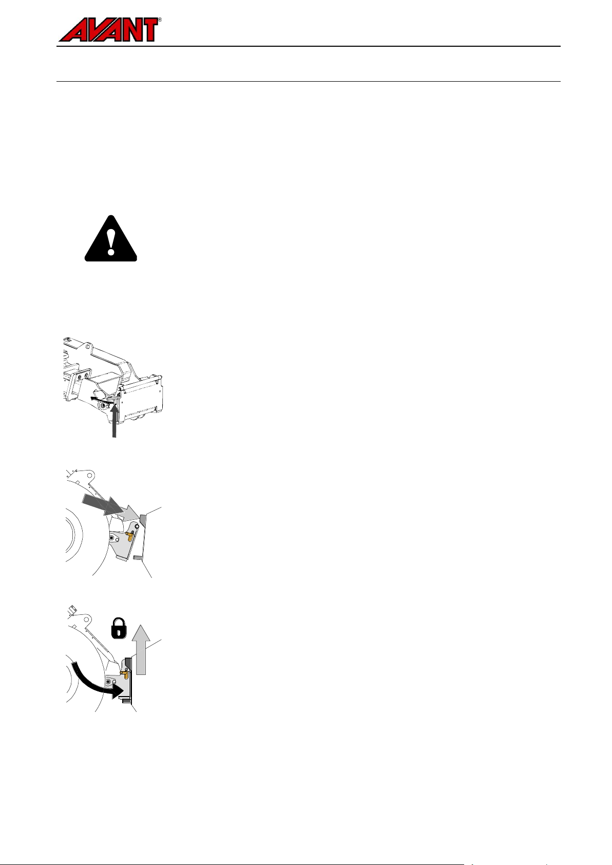
To disconnect the multi connector system:
Before disconnecting put the attachment down on a solid and even
surface.
1. Switch off the auxiliary hydraulics of the loader.
2. While pushing unlock button, turn the lever to disconnect the
connector.
3. After ending operation put the multi connector on its holder on the
attachment.
Conventional quick couplings
(alternative couplings for some loader models):
Before connecting or disconnecting the standard quick couplings, the
residual pressure must be released as shown below. The conventional
quick couplings will not connect, if there is pressure in the hydraulic
system.
When uncoupling the attachment, always disconnect the hydraulic couplings before
unlocking the quick attach plate, to prevent hose damage and any oil spills. Reinstall the
protective caps on the fittings to prevent impurities from entering the hydraulic system.
The lever should move easily all the way to its locking position. If the lever does not slide smoothly, check the
alignment and position of the connector and clean the connectors. Also shut down the loader and release the
residual hydraulic pressure.
To connect and disconnect the standard couplings, move the collar at the end of the female fitting. The hoses
should be connected so that the fitting equipped with a coloured cap is connected to the corresponding fitting
of the loader. Note that the protective caps on the loader and the attachment can be fastened to each other
during operation to reduce the accumulation of dirt. When disconnecting the standard quick couplings a small
amount of oil may drip from the couplings. Wear protective gloves and have some cloth at hand to keep the
equipment clean.
Disconnecting hydraulic hoses:
Before disconnecting the fittings, lower the attachment to safe position on solid and level surface. Turn the
control lever of the auxiliary hydraulics to its neutral position.
Releasing residual hydraulic pressure:
In case residual pressure is left in the hydraulic system of the attachment, it is often possible to disconnect the
hydraulic couplings, but it may be difficult to connect them the next time. If the fittings will not connect, the
residual pressure must be released by turning the auxiliary hydraulics control lever of the loader, when the
engine is turned off. To make sure that there will not be residual pressure in the hydraulic system of the
attachment, shut down the loader engine and move the auxiliary hydraulics control lever of the loader back
and forth before disconnecting the couplings.

14 (22)
Avoid overturning of the machine. Do not extend the
telescopic boom, when the load approaches the lifting
capacity of the loader, or when the loader boom is in
horizontal position. If the load indicator of the loader (if
fitted) signals, lower the load calmly and retract the
telescopic boom. Avoid sudden changes in speed or
direction whenever the load is lifted. Use additional
counterweights as needed.
Never use the loader or its attachments to lift persons or
as any kind of work platform even temporarily. Never
climb on the attachment.
6. Instructions for use
Practise the use of the attachment and the controls of the loader in a safe area. If you are unfamiliar with the
particular loader model, it is recommended to practice its use without any attachments.
6.1 Checks before use
Ensure that bystanders are at a safe distance when operating the equipment. Do not let anyone to
enter danger area of the boom or to stay directly in front of the loader. Also make sure that it is safe to
reverse with the loader. Never assume that bystanders will remain where you last saw them;
especially children are often attracted to the moving equipment.
Check the general condition of the attachment and the loader, and check for possible hydraulic oil
leaks. The attachment must not be used, if there is a fault in the hydraulic system of the loader or the
attachment. Refer to Chapter 7 for maintenance instructions.
Operate the attachment and the controls of the loader only when seated on the driver’s seat. Ensure
that the loader and the attachment are used in a safe manner and as intended. Do not allow children
to operate the equipment.
Never operate the loader or attachments while under the influence of alcohol, drugs, medication that
may impair judgement or cause drowsiness, or if not otherwise medically fit to operate the equipment.
Remember correct working methods and avoid leaving the driver’s seat unnecessarily.

15 (22)
1
Drive slowly, using moderate
to high engine rpm.
Once the tip of the bucket is
in the pile, begin to tilt the
bucket.
2
Scoop the bucket full by
simultaneous driving forward,
tilting, and lifting the bucket.
3
Once the bucket is almost full,
lift the bucket with loader
boom.
Keep driving slowly forward.
.
6.2 Using a bucket
Correct working method is important when lifting material from a pile, as lifting material from a pile requires the
most power from the loader. Use high engine rpm and read the instructions how to operate the loader
correctly from the operator’s manual of the loader.
Filling a bucket by pushing towards a pile of heavy material and then trying to lift or tilt the bucket is not
possible with any loader type. The loading is most effective when only the tip of the bucket is pushed into the
pile, and then, by simultaneous driving, lifting and tilting the equipment, material is cut into the bucket.

16 (22)
Move the auxiliary
hydraulics control lever
towards its locking
position (or use the
electric buttons of the
optional electric joystick)
to open the bucket.
The lever should not be
left to the locking
position.
Move the lever away
from the locking position
to close the bucket.
Always transport the bucket as
low and close to the ground as
possible. Lift only at unloading
location. Keep the telescopic
boom retracted.
Avoid hazards related to sudden stopping of the loader. Hitting an obstacle will stop the
loader suddenly, for example in snow clearing work. Check the operating area before
operation and use the seat belt.
When lifting material to a high level, the front plate must be simultaneously tilted to
prevent the load from falling from on the loader or the operator. Fitting the loader with the
boom self leveling option makes the repeated lifting work easier.
.
If the loader is not equipped with the boom self leveling:

17 (22)
If the load is too heavy when lifting load from a high level, the loader could tip forward
when reversing with the loader. Never reverse and drag with the loader before making
sure that the loader can handle the load that is being lifted.
Pay attention that a heavy load or long distance between the loader and the centre of
gravity of the load will affect the balance and handling of the loader. The use of additional
counterweights is recommended especially when operating smaller loader models. For
200-series loader the wheel weights are recommended. With heavy loads, the telescopic
boom must be kept retracted while moving with the loader.
Material
Density of material, (indicative),
kg / l (t / m³)
Snow
0,2 - 0,8
Example:
General bucket A36709 (volume 220 l, empty
weight 78 kg) is filled with gravel.
The weight of the load, depending on the actual
density of the material, is roughly between 1,7 *
220 +79 = 450 kg and 1,9 * 220 + 79 = 500 kg.
The load carrying capacity must be estimated by
taking in account the compactness of the material
and the evenness of the load
Wood chips
0,15 - 0,3
Wood pellet
~ 0,65
Peat
0,4 - 0,7
Soil
1,5 - 1,8
Gravel
1,7 - 1,9
Sand
1,5 - 2
Concrete, dry
1,7 – 2,5
Crushed rock
1,65 - 2,6
6.3 Material handling
Use maximum load indicated in the diagram of the operator’s manual of the loader as a guideline. Remember
that the actual load carrying capacity varies according to operating conditions, especially unevenness of
operating area has a great effect. Be especially careful when the load sensor indicator is activated. Also,
make sure that the ground surface is firm and follow recommended tire pressures.
The information shown in Table can be used to estimate the weight of the load and to avoid too heavy loads.
The values shown in table are intended to serve as general guidelines. Actual material densities may vary
greatly according to factors such as moisture content and compactness of the material.
Table - Typical material densities

18 (22)
.
6.4 Operating on inclined terrain
Extra caution is needed when using the equipment on inclined terrains and slopes. Drive slowly especially on
inclined, uneven, or slippery surfaces, and avoid sudden changes in speed or direction. Operate the controls
of the loader with careful and smooth movements. Watch out for ditches, holes on the ground, and other
obstacles, as hitting an obstacle may cause the loader to tip over.
Maximum lifting capacity can not be achieved on inclined terrain. On horizontally tilted terrain the load must
not be lifted high. The loader frame articulation should be kept straight when lifting heavy loads; turning the
load during lifting operation will affect the stability of the loader and may lead to overturning of the machine.
6.4.1 Operation with the tilt adapter
When working on slightly inclined terrains, the tilt adapter A34148 is an useful attachment (available for
loaders in 300-700 –series and R series). The adapter is fitted in between the attachment and the quick
coupling plate of the loader. The adapter allows the attachment to be tilted ±12.5 degrees sideways. Read the
instructions provided with the tilt adapter. More information about the tilt adapter is available from your AVANT
retailer or from the AVANT web pages at www.avanttecno.com.

19 (22)
Make sure the attachment is properly supported during all maintenance work. Never go
under a lifted attachment. The loader boom may lower unexpectedly during maintenance
causing serious injuries even when the loader engine is not running. All maintenance and
service must be performed when the attachment has been lowered down to a safe
position.
Never handle hydraulic components when the
hydraulic system is pressurised, since a fitting
may break or become loose and the released
oil may cause serious injuries. Do not use the
equipment, if you have discovered a fault in
the hydraulic system.
7. Maintenance and Service
The attachment has been designed to be as maintenance free as possible. Continuous maintenance includes
regular cleaning and lubrication, and monitoring the condition of the attachment. Because of the crushing
hazard caused by lowering machine parts, all maintenance work must be done when moving parts have been
lowered down completely and the attachment is lowered flat against the ground.
7.1 Checking hydraulic components
Check the condition of the hydraulic hoses and components when the engine has been turned off and the
pressure has been relieved. Do not use the equipment, if you have discovered a leak in the hydraulic system
of the attachment or the loader. Leaking hydraulic fluid may penetrate skin and cause serious injuries. Seek
medical attention immediately in case hydraulic fluid penetrates the skin. Wash any part of body that has been
in contact with hydraulic oil carefully with water and soap. Hydraulic fluid is also harmful to the environment
and any leak to the environment must be prevented. Repair all leaks immediately after detecting them; a small
leak can quickly grow into a big one. Operate the attachment only with type of hydraulic oil that is accepted for
use in Avant loaders.
Check hoses visually for cracks or abrasions. If there are signs of leaks, to check a component, hold up a
piece of cardboard in the area where a leak is suspected. Do not use hands to search for leaks. Monitor the
wearing of the hoses and stop the use, if the surface layer of any hose has worn off. Check the routing of the
hoses; adjust the hose clamps to avoid abrasion to the hoses. The hoses have limited service life. Depending
on operating conditions all hoses must be inspected thoroughly no later than after 3 to 5 years of use, and if
required, they must be replaced with new ones.
Finding any fault means that the hydraulic hose or component must be replaced and the equipment must not
be used until it is repaired. Spare parts are available from your nearest AVANT retailer or authorised service
point. Leave the repair work to professional service technicians, if you don’t have adequate knowledge and
experience about hydraulic assemblies and how to perform the repairing safely.
7.2 Cleaning the attachment
Clean the attachment regularly to prevent accumulation of dirt which is more difficult to remove. You may use
a pressure washer and a mild detergent. Do not use strong solvents, and do not spray directly at the hydraulic
components, or at the labels on the attachment.
Do not store the attachment directly against the ground; place it on blocks of wood or on a pallet, for example.
For longer storage periods touch up the paint where needed, grease the lubrication points and oil the visible
parts of the hydraulic cylinder shaft to prevent rust damage.

20 (22)
There are a total of 6 lubrication points at the
joints of the attachment. A small amount of grease
should be added regularly.
Suitable lubrication interval depends heavily on
operating conditions but lubricant must be added
at least after every 10 hours of use. Adequate
lubrication of the joints must be ensured, and if
the joints have become dirty, lubricant must be
added; added lubricant will push out dirt from
joints.
Clean the end of the nipple before greasing and
add only a small amount of grease at a time. All
lubrication nipples are standard R1/8" nipples.
Replace any damaged nipples.
.
..
Leave the attachment to a position where water will not stay in the attachment.
7.3 Checking metal structures
Also the metal structures of the attachment must be inspected regularly. Check visually for damages and
inspect the quick attach brackets and their surrounding area carefully. The attachment must not be used if it is
deformed, cracked, or torn.
Welding repairs are only allowed to be carried out by professional welders. When welding, only methods and
additives suited for steel used in bucket must be used. For more information about repairs contact your
nearest service point.
7.4 Lubrication
8. Warranty terms
Avant Tecno Oy grants a warranty of one year (12 months) from the date of purchase for the attachment it
manufactures.
The warranty covers repair costs as follows:
Work costs are covered, if the repair is not performed at the factory.
The factory replaces any defective components or consumables.
The factory may reimburse the price of components purchased by the customer in special cases that have
been agreed in advance.
The warranty does not cover:
Normal maintenance work or parts and consumables required for it.
Damages caused by unusual operating conditions or ways of use, negligence, structural changes made
without the consent of Avant Tecno Oy, use of non-original parts or lack of maintenance.
Consequences of a defect, such as interruption of work or other possible additional damages.
Travel and/or freight costs caused by the repair.

4 in 1 Bucket 2016 2
EY-vaatimustenmukaisuusvakuutus
EG-försäkran om överensstämmelse
EU samsvarserklæring
EF-overensstemmelseserklæring
EC Declaration of Conformity
EG-Konformitätserklärung
Déclaration de conformité CE
Valmistaja / Tillverkare / Produsent / Producent / Manufacturer / Hersteller
Fabricant:
AVANT TECNO OY
Osoite / Adress / Adresse / Address / Adresse:
Ylötie 1
33470 YLÖJÄRVI, FINLAND
Avant
Hydraulitoiminen kauha; Avant-kuormaajan työlaite
Hydraulisk skopa; arbetsredskap för Avant lastare
Hydraulisk skuffe; redskap for Avant minilastere
Hydraulisk skovl;redskab til Avant Minilæssere
Hydraulic bucket; attachment for Avant loaders
Hydraulische Schaufel; Anbaugerät für Avant Radlader
Godet à commande hydraulique destinée à être utilisée avec les chargeuses Avant
1100 mm
1280 mm
1400 mm
A21245
A21249
A21156
A21184
A21266
A21269
11.3.2016 Ylöjärvi, Finland
Risto Käkelä,
Toimitusjohtaja / Verkställande direktör / Administrerende direktør /
Managing Director / Geschäftsführer / Directeur général
Vakuutamme täten, että alla mainitut tuotteet täyttävät konedirektiivin turvallisuus- ja terveysvaatimukset (direktiivi
2006/42/EY muutoksineen). Seuraavia yhdenmukaistettuja standardeja on sovellettu /
Vi försäkrar härmed att nedan beskrivna produkter överensstämmer med hälso- och säkerhetskrav i EG-maskindirektiv
(EG-direktiv 2006/42/EG som ändrat). Följande harmoniserade standarder har tillämpats /
Vi erklærer herved at produktet som er oppgitt under er i samsvar med forskriftene i Maskindirektivet (direktiv 2006/42/EC
med endringer). Følgende harmoniserte standarder har blitt anvendt /
Vi erklærer herved, at nedenstående produkter er i overensstemmelse med bestemmelserne i maskindirektivet (direktiv
2006/42/EF indeholdende ændringer). Følgende harmoniserede standarder er anvendt /
We hereby declare that the products listed below are in conformity with the provisions of the Machinery Directive (directive
2006/42/EC as amended). The following harmonized standards have been applied /
Wir erklären hiermit, dass die nachstehend aufgeführte Maschine konform ist mit den Bestimmungen der
EG-Maschinenrichtlinie (EG-Richtlinie 2006/42/EG mit Änderungen). Die folgende harmonisierte Normen wurden
angewandt:
Nous déclarons par la présente que les produits mentionnés ci-dessous sont conformes aux exigences en matière de
sécurité et de santé de la directive relative aux machines (directive 2006/42/CE, avec ses modifications) Les normes
harmonisées suivantes ont été appliquées
SFS-EN ISO 12100, SFS-EN ISO 4413
Mallit / Modeller / Modeller / Modeller / Models / Modellen:

 Loading...