

English
Operator's Manual
2016-
www.avanttecno.com

Avant 220/225 2017 1
2
TABLE OF CONTENTS
INTRODUCTION ....................................................... 3
Foreword ................................................................................... 3
Make sure all relevant manuals are available ..................... 4
Intended use .............................................................................. 5
Avant warranty ......................................................................... 7
SAFETY FIRST ............................................................ 8
General safety instructions .................................................... 8
Operation on uneven surfaces, gradients, and near
excavations ................................................................................ 11
Personal safety and protective equipment......................... 11
Electric system and handling the battery ........................... 13
Handling fuel (220/225) .......................................................... 14
LPG Fuel - Safety (225LPG) ................................................... 15
Safety of LPG systems ............................................................. 15
DESCRIPTION OF THE LOADER ............................ 17
Identification of the loader .................................................... 17
Main parts of the loader ......................................................... 18
Signs and decals ........................................................................ 19
Technical specifications .......................................................... 23
General specifications ............................................................. 24
Tyres............................................................................................ 25
Wheel spacers .......................................................................... 25
Wheel weights (optional extra) ........................................... 25
Fuel requirements .................................................................... 26
Engine oil requirements .......................................................... 27
Auxiliary hydraulics oil flow .................................................. 27
Tipping load ............................................................................... 28
CONTROLS OF THE LOADER ................................ 30
Parking brake lever .................................................................. 30
Dashboard .................................................................................. 31
Indicator lights .......................................................................... 31
Control of loader boom, auxiliary hydraulics and
other functions ......................................................................... 32
Engine compartment ............................................................... 34
Battery disconnect switch ...................................................... 34
Trailer coupling ......................................................................... 34
Rear auxiliary hydraulics outlet (option) ............................ 35
Engine heater (option) ............................................................ 35
Electric 12 V outlet .................................................................. 35
Seat - Seat belt and seat adjustments .................................. 36
Seat heater ................................................................................. 36
Lights ........................................................................................... 37
CAB L (optional extra) ........................................................... 38
OPERATING INSTRUCTIONS ................................. 39
Starting the engine ................................................................... 40
Ignition key ................................................................................. 40
Stopping the engine (Safe stopping procedure) ................ 41
Drive control ............................................................................. 42
In case the machine tips over ................................................ 44
Material handling ....................................................................... 45
Refuelling (220/225) ................................................................. 46
Replacing a gas bottle (225LPG) ........................................... 47
Transporting instructions and tie down points ................ 48
Storage ........................................................................................ 49
WORKING WITH ATTACHMENTS ........................ 51
Requirements for attachments ............................................. 51
Coupling the attachments ...................................................... 52
Coupling the hydraulic hoses of the attachment ............. 54
Using the auxiliary hydraulics ................................................ 55
Releasing the residual pressure of hydraulic systems ..... 56
SERVICE AND MAINTENANCE ............................... 57
Installing of service support and frame lock ...................... 59
Daily inspections ....................................................................... 60
Maintenance schedule ............................................................. 61
Loader maintenance ................................................................ 62
Engine maintenance ................................................................. 67
Engine service ............................................................................ 67
Fuel system, gasoline 220/225 ............................................... 70
Fuel system, 225LPG ............................................................... 71
Jump start and auxiliary power ............................................. 73
TROUBLESHOOT ...................................................... 74
SERVICES MADE ........................................................ 76
INDEX .......................................................................... 82
Original instructions
Avant 220/225
3
Introduction
Foreword
AVANT TECNO OY wants to thank you for purchasing this AVANT loader. It is the result of Avant’s long
experience in design and manufacturing of compact loaders. We ask you that you read and understand the
contents of this manual completely before operating the loader. This operator’s manual is intended to help you to:
operate this machine safely and efficiently
observe and prevent situations that may cause a risk of physical injury or danger
keep the machine in good condition and its life span as long as possible
The following warning symbols and signal words are used throughout this manual to indicate factors that must be
taken into account to reduce the risk of personal injury or damage to property:
WARNING:
This safety symbol refers to important safety information in this manual.
It warns of an immediate hazard that could cause serious personal
injury.
Read the warning text accompanying the symbol carefully and ensure
that other operators are also familiar with the warnings, since personal
safety is at stake.
DANGER:
This signal word indicates a hazardous situation which, if not avoided, will cause death or
serious injury.
WARNING:
This signal word indicates a potentially hazardous situation which, if not avoided, could
cause serious injury or death.
CAUTION:
This signal word is used when minor injury could result if the instructions are not followed
properly.
This signal word indicates information about the correct operation and maintenance
of the equipment.
Failure to observe the instructions accompanying the symbol can lead to equipment
breakdown or other property damage.
Avant 220/225
4
.
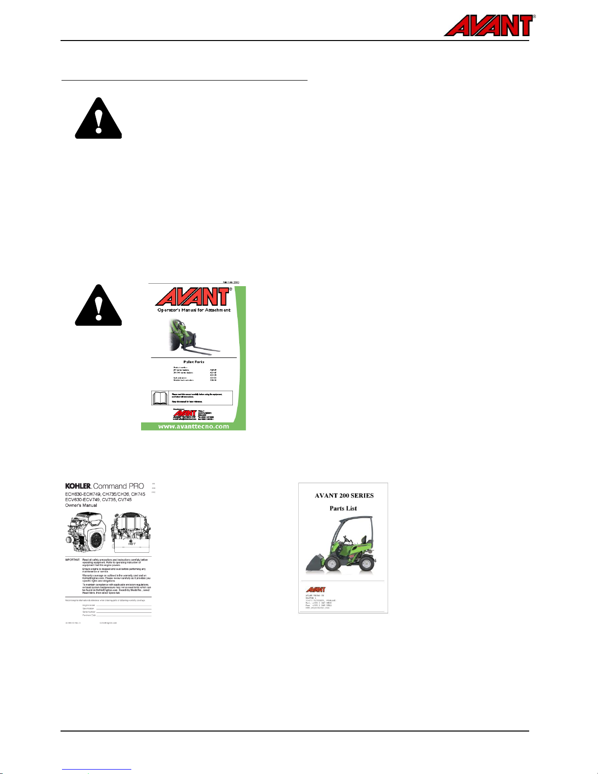
Make sure all relevant manuals are available
DANGER
Wrong use of the equipment can cause death or severe injuries - Make sure to read
all relevant manuals and instructions thoroughly and keep them available for all
operators.
Using each attachment requires specific information about correct use, mounting
procedure, safety, and how to avoid hazardous situations. An attachment may introduce
risks that are not present when operating the loader with other kinds of attachments.
Always read the operator's manual of each attachment carefully.
Manuals of attachments
DANGER
Attachments can create significant risks that are not
covered by this Operator's manual of the loader.
Make sure you have all attachments manual available.
Wrong use of an attachment can cause serious injuries or
death.
Each attachment is accompanied by its own respective
Operator’s Manual. The manual will show important
information related to safety, and how to attach, use, and
maintain each attachment correctly.
Engine manual
Spare parts list
In addition to this
Operator’s manual of
the loader, ensure that
you have received and
read also the original
Engine owner’s
manual.
The instructions
concerning the engine
must be followed. If
conflicting information
is found, the
information shown in
the Operator’s Manual
of the loader must be
followed.
All spare parts of the loader are
listed in a separate spare parts
list. Engine related parts are
listed in the spare parts list of
the engine.

Avant 220/225
5
.
Intended use
Avant 220/225/225LPG are articulated compact loaders, designed and manufactured for both private and
professional use. The loader can be equipped with attachments offered by Avant Tecno Oy, which enables
performing several different jobs. Because of this multi-purpose nature of the machine and the various
attachments and tasks, read always not only this Manual but also the Operator's Manual of the attachment, and
follow all instructions. Every person who has to do with this machine must follow work safety regulations, all other
generally accepted rules related to work health and safety, and all road traffic regulations.
Remember that safety consists of several factors. The loader, equipped with an attachment is very powerful and
can cause serious personal injuries or property damages if it is operated in a wrong or careless way. Do not
operate an attachment unless you have familiarised yourself with the use of it and the eventual dangers related to
it. The loader is not intended to lift or transport people or be used as a work platform. Different jobs require
different attachments, and it is not allowed to handle loads without any attachment fitted. The loader must not be
used in underground or tunneling work.
Contact your local AVANT dealer, if you are uncertain of anything concerning the operation and maintenance of
this loader, or for any questions, service or spare parts.
In addition to the safety instructions included in this manual, you must observe all occupational safety regulations,
local laws, and other regulations concerning the use of the equipment. Particularly the regulations concerning the
use of the equipment on public road areas must be observed. Contact your Avant dealer for more information
about local requirements before you operate the loader on road areas. The use of LPG equipment on road areas
may be restricted or regulated.
This loader has been designed to require as little maintenance as possible. The operator can perform the routine
maintenance tasks. There are however more demanding service operations that must be done by professional
service personnel only. It is allowed to perform service operations only when wearing appropriate protective
equipment. Original spare parts must be used. Familiarise yourself with the service and maintenance instructions
in this Manual. Operating a loader that is in poor condition, or that has received unauthorised modifications, can be
hazardous to the operator and bystanders.
Gas operated 225LPG
The gas evaporation capability of the LPG cylinder limits the lowest operating temperature. Engine performance
may decrease significantly at temperatures below 0ºC (32ºF) and engine may not run. Even though the LPG
engine runs cleaner and produces less harmful emissions than gasoline engines, it is not intended or suitable to
be used in enclosed spaces or areas with poor ventilation. See warnings in this manual.
The gasoline and LPG engines have fundamental differences between each other. In addition to fuel delivery
system differences include engine valves and other major parts. The gasoline engine of the 225 cannot be
converted to LPG engine. Any attempt to modify the engine can cause risk of fire, poor performance, short service
life, and will void all warranties.

Avant 220/225
6
.
Operator qualification
Only operators who have studied this manual, and all relevant attachment manuals, are allowed to use this loader.
Regardless of your possible previous experience with lawn-mowers, loaders, ATVs, or other equipment, it is
important that you learn the driving principle of this loader. Practise how to operate the loader and its attachments
safely at an open area before you use the loader near other persons.
You must be in good physical and mental condition with the ability to stay alert and to observe the surrounding
area. Never use the equipment while under influence of medication which could impair your abilities to operate the
equipment safely. Do not operate the loader if you are under the influence of alcohol or any other intoxicant during
the work shift.
Depending on operating area, you may also be required to read, understand and comply with all applicable
Employer, Industry and Governmental rules, standards and regulations.
You can replace an empty gas bottle with a full one by yourself with the instructions shown in this manual. Any
other gas related service or repair, such as replacing a hose or a fitting, must be left to qualified service personnel.
Gas related service tasks may require a registered professional.
Versions of this manual
Avant has a policy on continuous product development. Updated versions of the manual replace the previous
versions of this manual as long as the year on the cover page matches with the original manual. You can ask for
the latest manual from your dealer. Some of the features or technical details presented in this manual may change
without notice. The pictures in this manual may show optional equipment or features that are not currently
available in your market area. We reserve the right to change the contents of the manual without notification.
Keep this Operators Manual with the machine at all times. If this Manual gets lost, ask for
a new copy from your Avant dealer. Remember also to give this Manual to the new owner
when the machine changes ownership.

Avant 220/225
7
.
Avant warranty
This warranty specifically applies to the Avant 220/225/225LPG loader only and not to any attachments used with
this product. Any repairs or modifications performed without the prior authorisation of Avant Tecno Oy will cancel
this warranty. During the first two years of operation or first 500 hours (whichever is the soonest) Avant Tecno Oy
warrants to replace any part or repair any defect which may occur, subject to the terms detailed below:
1. The product has received regular maintenance in accordance with schedules given by the manufacturer.
2. Any damage caused by operation in a negligent manner or exceeding the approved specifications detailed in
this manual is excluded.
3. Avant Tecno Oy accepts no responsibility for interruption to working or any other consequential losses
resulting from any failure of the product.
4. Only Avant Tecno Oy approved replacement or original quality parts shall be used during routine
maintenance.
5. Any damage caused by the use of incorrect fuel, lubricants, cooling liquid or cleaning solvents is excluded.
6. The Avant Warranty excludes any consumable parts (e.g. tyres, batteries, filters, belts etc.) except where it
can be clearly shown that these parts were defective on original supply.
7. Any damage caused resulting from the use of attachments not approved for use with this product is
excluded.
8. In the event a fault occurs which is attributable to manufacturing or assembly defect you should arrange to
return your AVANT to your authorised dealer for repair. Travel and freight costs are excluded.
.
..

Avant 220/225
8
Safety First
DANGER
Incorrect or careless operation of the loader may cause a serious accident. Before putting
the machine into operation, familiarise yourself with the use of the machine and read and
understand this Operator's Manual, as well as all relevant safety instructions, local
regulations, and safe working practices.
Understand the limitations of speed, braking, steering and stability as well as loading
capacity of the machine before starting operation. Make sure that everyone who operates
or works with this equipment is familiar with these safety precautions.
If you have no previous experience of the machine, make sure to do all testing at a safe
and open place with no persons in the area of operation.
General safety instructions
1. Remember the correct working position. When
driving, be comfortably seated in the driver´s
seat, keep your feet in their proper place in the
footwell and at least one hand on the steering
wheel.
2. When seated, always keep the seat belt
fastened and keep hands and feet inside the
operator’s area.
3. Before leaving driver’s seat, always:
Lower the loader boom and place attachment
flat on ground
Engage the parking brake
Stop the engine, remove the ignition key
4. Start the operation slowly and carefully.
Practise driving of the machine at a safe and
open place before connecting any attachment,
and follow the instructions in this Manual and
also the operator's manual of the attachment.
5. Operate the control levers with careful and
deliberate movements. Avoid abrupt
movements when handling the load, in order to
prevent the load from falling and to keep the
machine stable.
6. Keep away from the danger zone of the lifted
boom and don’t let anyone go there.
7. Keep your hands, feet and clothing away from
all moving parts, hydraulic components, and
hot surfaces.
8. Make sure that there is enough open space
around the machine for safe driving.
9. Do not transport the load with the boom lifted.
Always carry bucket or attachment as low as
possible, and put the load down whenever you
leave the machine.
10. It is not allowed to transport persons with this
machine. Do not transport or lift persons in the
bucket or in any other attachment.
11. Do not exceed the tipping load. Familiarise
yourself with and follow the load diagrams in
this Manual.
12. When turning with the machine, remember that
the driver´s seat extends beyond the turning
radius of the wheels (collision risk).
13. Do not operate the loader in an explosive
environment or in a place where dust or/and
gases can create a fire or explosion hazard.
14. Keep the engine area clean of flammable
materials.
15. Read the lifting, towing and transportation
instructions on page 48.
16. Switch off the battery disconnect switch
whenever leaving the machine unattended.
17. Follow all inspection, service and maintenance
instructions. If you notice any faults or
damages on the machine, these must be
repaired before starting operation.
18. Before any maintenance or repair operation
always stop the engine, lower the boom down
and release pressure from hydraulic system.
Read safety instructions for maintenance on
page 57.
Avant 220/225
9
19. Do not let any person operate this loader who
has not read safety instructions and is not
familiar with the safe and correct use of this
loader.
20. Never operate the loader or attachments while
under the influence of alcohol, drugs,
medication that may impair judgement or
cause drowsiness, or if not otherwise medically
fit to operate the equipment.
.
..
Suffocation hazard - Ensure ventilation
DANGER
Make sure that ventilation is
sufficient in the working area, even
when using a loader equipped with
an LPG engine. Using a loader in
poorly ventilated areas can cause
loss of consciousness and death
as carbon monoxide (CO) and
carbon dioxide (CO2) can be at
dangerous level within minutes.
Never operate the loader indoors or in partly
enclosed areas unless you've made sure there is
special ventilation system installed. Even LPG
engines are not safe to operate in enclosed or poorly
ventilated indoor areas. They produce carbon dioxide
(CO2) and can also emit carbon monoxide (CO)
under some conditions that can concentrate quickly
to a dangerous level. Never leave the engine
running in garages or sheds. Operate the loader
only outdoors and far from windows, doors, and
vents.
Elevated level of carbon dioxide or carbon monoxide
in breathing air can not be noticed without dedicated
measuring equipment. Signs of carbon monoxide
poisoning include nausea, headache, dizziness,
drowsiness, and lack of consciousness.
Get fresh air if anyone shows signs of carbon
monoxide poisoning and see a doctor.
.
..
Articulated frame - Risk of overturning
WARNING
Turning articulated frame can lead
to overturning of the loader on
inclined terrain or when driving at
high speed. Never turn frame
towards the slope while operating
on inclined ground.
Always drive slowly when carrying
load or when turning with the
machine.
.
..
Sudden movements can tip the machine over Risk of overturning
WARNING
Movements, such as stopping,
turning, or lowering the boom
abruptly, can cause loss of
stability. Always drive slowly and
operate the controls of the loader
very carefully, especially when
handling heavy loads.
.
..
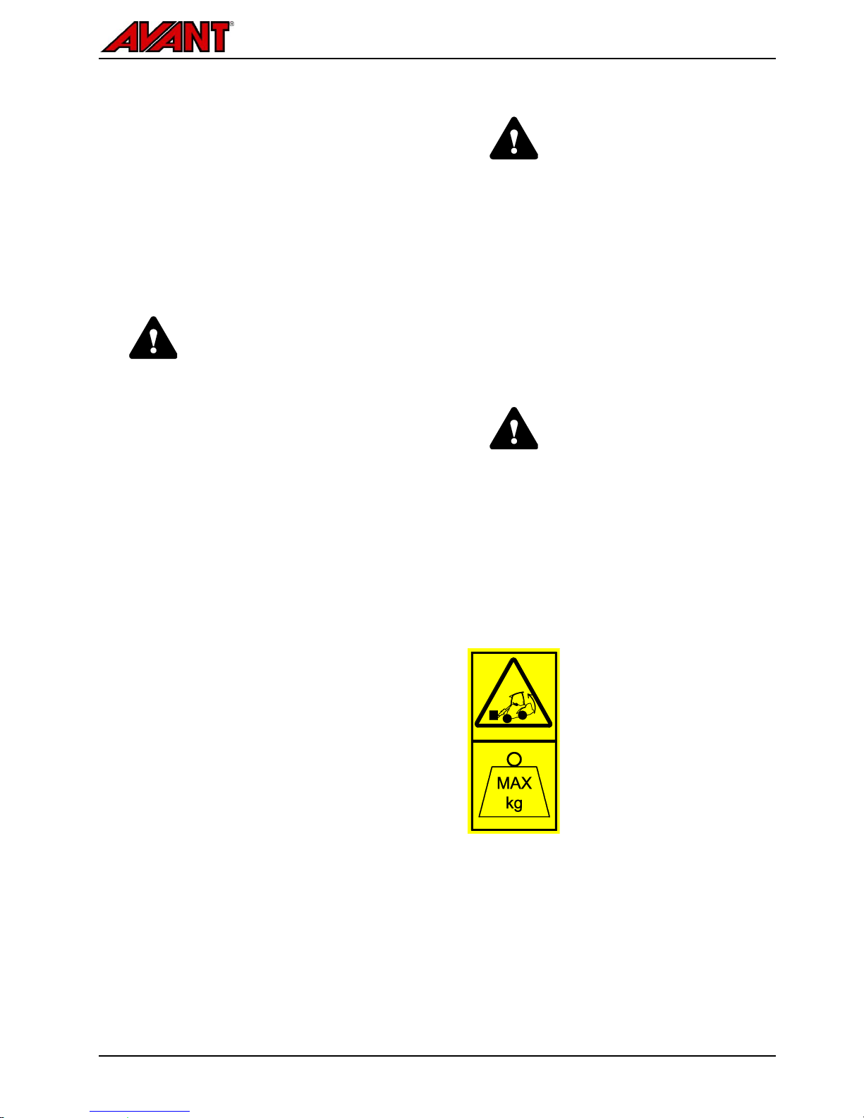
Overload - Risk of overturning
CAUTION
The high lift capacity of the loader
makes it possible to exceed the
stability of the loader when
handling loads. Read the
instructions regarding maximum lift
capacity and load handling in this
Operator's Manual. Following the
instructions reduces the risk of
tipping the machine over its front
axle, but the operator must be
aware of the limits of the machine
and follow safe working practises
to avoid overturning of the
machine.
.
..
Avant 220/225
10
WARNING
Never take a heavy load on the
loader from high level – e.g. from
truck, shelf etc. – risk of tipping
over!
If the load is too heavy when lifting
load from a high level, the loader
could tip forward when reversing
with the loader.
Never reverse and drag with the
loader before you make sure that
the loader can handle the load that
is being lifted.
When loading, always keep the
loader frame as straight as
possible.
.
..
Falling of load or unexpected lowering of loader
boom - Risk of crushing
WARNING
Always remember that the boom
may lower unexpectedly due to
loss of stability, mechanical fault,
or if another person operates the
controls of the loader, leading to
crushing hazard. The attachment
or the loader are not intended to be
left to keep a load elevated for
longer periods. Lower the
attachment before leaving the
driver's seat. The stability of the
loader may change when leaving
the driver’s seat, leading to tipping
over of the machine.
.
..
Risk of falling objects
WARNING
Make sure load is securely on the
attachment. Never tilt the
attachment back when it is lifted
high. Operate only with machines
equipped with ROPS and FOPS
structures.
.
..
Falling of persons - Risk of crushing
WARNING
Never use the loader or its
attachments to lift persons or as
any kind of work platform even
temporarily. Never climb on the
loader or on the attachment.
Seating capacity: one person only.
.
..

Avant 220/225
11
Operation on uneven surfaces,
gradients, and near excavations
Extra caution is needed when using the equipment
on inclined terrains and slopes. Drive slowly
especially on inclined, uneven, or slippery surfaces,
and avoid sudden changes in speed or direction.
Operate the controls of the loader with careful and
smooth movements. Watch out for ditches, holes on
the ground, and other obstacles, as hitting an
obstacle may cause the loader to tip over.
Overturning of machine can lead to death or
serious injury
WARNING
The stability and the load handling
capacity of the loader are
significantly reduced on inclined
terrains and maximum lifting
capacity can be achieved only on
firm, level ground. On horizontally
tilted terrain the load must be kept
close to the ground and must
never be lifted high.
.
..
Handle heavy loads only on even surfaces.
Drive very slowly on uneven terrains. Load,
unload, and turn the machine on flat level ground
only. Lifting a load or turning on uneven surfaces
can lead to loss of stability.
Do not drive on too steep a gradient - watch out
for ditches, manholes and steep gradients, which
may cause the loader to tip over.
Never drive along an excavation. Note that the
excavation or trench may suddenly cave in.
Exercise extreme caution when driving near
ditches or embankments, and avoid driving along
a ditch or trench, as the machine could suddenly
tip over if an edge caves in. Avoid driving along
trenches and keep at least a distance equal to
width of a trench.
Do not park the machine on a surface with a
gradient. Should this be necessary, engage the
parking brake and preferably turn the machine
sideways and put down the load. If needed, use
chocks behind the wheels.
Personal safety and protective
equipment
Wear safe clothing and personal protective
equipment.
Protect yourself against work hazards like noise,
ejecting debris or dust for example.
Follow regulations regarding protective
equipment. Wear eye protection and hard hat or
other protective equipment as needed.
Read Operator's Manual of the attachment for
more information about protective equipment
needed in the work.
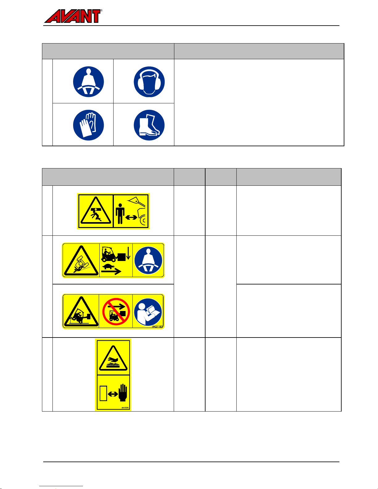
The noise level at the driver's
seat may exceed 85 dB(A).
Wear hearing protection while
working with the loader.
Wear protective gloves.
Wear safety boots whenever
working with the loader.
Wear safety glasses when
handling hydraulic components.
Always fasten seat belt while
operating the machine.
When working at construction
sites, a safety helmet is
recommended and may be
mandatory in addition to the
falling objects protective
structure (FOPS) on the loader.
Depending on work and working
area, also a respirator mask may
be required. Find out about other
necessary safety equipment at
your specific work site.
Avant 220/225
12
CAUTION
Silica dust warning. Prolonged
exposure to crystalline silica can
cause a lung disease called
silicosis. Occupational health and
safety officials recommend limiting
exposure to dust that is present at
most earth-moving and many other
work sites. Avoid spreading of dust
where possible, keep loader cabin
clean from dust, use respiration
mask when necessary.
Safety frame (ROPS) and safety
canopy (FOPS)
The loader is equipped with a Rolling Over Protective
Structure (ROPS) and a Falling Object Protective
structure (FOPS). These safety structures are
important parts of operator safety, and they must be
fitted on the machine.
Safety frame (ROPS) protects the operator in case
the machine tips over. Fasten seat belt while
operating a machine with a ROPS. All cab versions
are ROPS & FOPS tested and certified.
Crushing hazard - Always keep safety structures
installed
WARNING
Never take off the safety
structures, modify them, or attempt
to repair. If damaged, contact
service.
Always fasten the seat belt in order
to stay inside the protected area of
the safety frame.
Modifications
Any modification to this machine must be approved
beforehand by an authorised Avant representative. If
you modify the loader or attachment, it can become
dangerous and cause serious injuries or even death.
Unauthorised modifications can increase the risk of
accidents and damage or shorten the service life of
the machine. Modifications to engine can make it no
longer compliant with emission regulations. Use only
original spare parts to make sure that the product is
kept in safe operating condition.
Avant 220/225
13
.
Electric system and handling the battery
Always handle the battery with care. Follow the
safety instructions given below. The battery of the 12
v electric system of the loader is located under a
cover plate under the floor of the loader. See page
63 for more information about battery and
maintenance instructions.
WARNING
Short-circuit of the battery can
create fire or explosion. Disconnect
the battery with the battery
disconnect switch before working
on the engine or equipment. Never
lay metal objects on the battery.
WARNING
Battery acid can cause severe skin
burns. Handle damaged battery
with extreme care and wear
appropriate safety gloves and
clothing. Battery is a sealed type
battery, meaning that you should
never attempt to open the battery.
WARNING
Lead acid batteries produce
flammable and explosive gases
during charging. Make sure that
ventilation is sufficient when
charging the battery. Keep arcs,
sparks, flames, and lighted
tobacco away from battery.
Never charge a frozen battery. A
frozen battery can explode during
charging.
CAUTION
Battery and its terminals contain
lead, a harmful substance which
should not be handled more than
what is necessary. Wash hands
with soap and water after handling
the battery.
Battery contains corrosive sulphuric acid which
causes serious burns upon skin contact. Avoid
contact with skin or clothes. If electrolyte gets on
your skin or clothes, flush with a lot of water. In
case of contact with eyes, flush with a lot of
water for at least 15 minutes and see a doctor
immediately.
In order to avoid spark emissions, always
disconnect the negative (-) cable first and
connect it last.
Before connecting the battery cables make sure
that the polarity is correct: Faulty connection will
seriously damage the electric system of the
engine and may cause sparks, fire, or explosion
of the battery.
If fuse is blown repeatedly, find out the cause.
Always use fuses with correct rating.
Read the instructions for jump start, see page
72
Avant 220/225
14
Working near powerlines
Digging may expose buried electric cables, and
some attachments may make it possible to reach
overhead powerlines with the loader, creating hazard
of electric shock and electrocution.
Plan work ahead and take necessary safety
precautions.
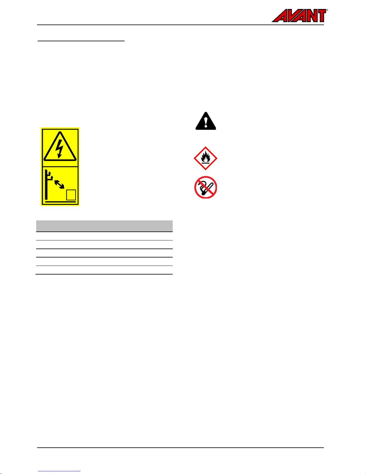
Stay away from electric cables - Electrocution
hazard
DANGER
Electric shock hazard - Contact
with or working too close to electric
wires can result in lethal electric
shock. Keep the loader and any
attachment at a sufficient distance
from all electric cables, see table
below.
Table 1 - Safety distance from powerlines
Voltage level
Safety distance
0 - 1000 V
2 m
1 - 45 kV
3 m
110 kV
4 m
220 kV -
5 m
Unknown voltage
5 m
If electric cables are exposed during digging, or in
case of inadvertent contact or proximity with live
electric source:
Do not leave the loader until the electricity has
been disconnected by qualified technicians,
usually local electric company.
If absolutely necessary, jump out from the
loader, keeping feet next to each other, until at a
safe distance.
Warn others not to approach the loader until safe
to do so.
Handling fuel (220/225)
Refuel with correct type of fuel specified in this
manual, and follow refuelling instructions on page
46. Store fuel carefully in an approved container
away from heat and sources of ignition.
Always have correct type of fuel tank cap fitted and
avoid spilling of fuel.
Risk of fire or explosion - Handle fuel with care
DANGER
Always stop the engine and allow it
to cool before refuelling.
Refuel only in a well ventilated area.
Do not overfill the fuel tank. Leave at
least 50 mm below the neck of the
fuel tank to avoid spilling of fuel.
Avoid spilling fuel when refuelling.
Should this happen, wipe the fuel
away immediately in order to avoid
risk of fire.
Keep fuel away from sources of
ignition. Do not smoke during
refuelling.
Avant 220/225
15
LPG Fuel - Safety (225LPG)
Liquefied Petroleum Gas is extremely flammable and
is heavier than air and tends to settle in low areas
where a spark or flame could ignite gas.
Do not start or operate this engine in a poorly
ventilated area where leaking gas could accumulate
and endanger safety of persons in area.
Handle the LPG equipment with care and stop the
use of the loader immediately if you think that it may
be damaged. Contact authorised service to sort out
the problem.
See storage instructions on page 49.
Fuel can explode or burn, risk of severe burns and
personal injury - No smoking or open flames near
fuel
DANGER
Always stop the engine and allow
it to cool before changing a gas
cylinder.
Close the manual valve of the gas
cylinder and let the engine run
until gas hoses are empty before
disconnecting any fitting.
Make sure you use correct type of
LPG gas and that hose fittings are
correct for the bottle type.
Always keep LPG cylinders in
upright position. Store LPG gas
bottles correctly. See page 49.
Keep fuel away from heat and
sources of ignition. Do not smoke
when handling gas.
Leaking gas is heavier than air.
Safety of LPG systems
Keep the entire LPG system in good condition to
keep the LPG system safe and to avoid leaks. Use
only correct type of gas bottles, refer to page 26.
Improperly installed and maintained gas equipment
can cause fuel supply system or other components
to malfunction, causing gas leaks. It is recommended
to have the LPG system inspected annually (hoses,
fittings, pressure regulator). Propane fuel supply
systems must be installed and serviced only by
qualified service professionals. Observe all local
regulations concerning the handling of LPG
equipment.
Handling of LPG bottles
Always keep gas bottle upright. This ensures that the
overpressure relief of the bottle can function as
intended.
Stop the engine and switch off the main current with
the battery disconnect switch before changing the
gas bottle.
Make sure the gas bottle has an overpressure relief
valve fitted. Pressure inside the gas bottle depends
on ambient temperature. In case of overpressure in
the cylinder, the overpressure relief valve will vent
out propane to keep pressure inside the tank at a
safe level.
Close the manual shut off valve on the gas bottle
carefully, do not overtighten the valve. Typically the
valve needs to be opened about 2-3 rounds to be
fully open.
Notice the inspection year that has been marked on
the bottle. The gas bottle must be inspected by a
licenced professional before the year marked on the
bottle. If there are no markings on the bottle, or the
inspection date has passed, the gas bottle must be
taken out of service and returned to the retailer.
Avant 220/225
16
WARNING
Risk of gas leak, fire or
explosion - Handle gas bottles
with care. Disconnect the gas
cylinder from the loader and store
it separately in an area designated
for safe propane storage, see page
49. If the gas bottle is damaged, or
if damage is otherwise suspected,
remove it from service and take it
to exchange point or qualified
inspector.
Filling of gas bottle
In some areas empty gas bottles are exchanged to
full ones, and in other areas they are filled. Filling of
a gas bottle requires special equipment and training.
If filling a bottle, the condition of the bottle and the
valve must be checked by a qualified specialist. Only
professionals who have been trained to fill gas
bottles and have a valid licence are allowed to fill a
gas bottle. Never attempt to fill a gas bottle without
special equipment needed to avoid risk of explosion.
Use with LPG only
Do not use natural gas or any other gas that contains
methane (common names for these include biogas
EPG / CBG and CNG). In addition to the differences
in composition between these and other gases, the
working pressures and the gas systems themselves
can be very different. This loader is intended to be
used only with a gas bottle that contains propane.
WARNING
Risk of fire or explosion - Use
only correct LPG gas and gas
bottle. If you use other gas types,
there is a serious risk of fire and
explosion, or engine damage at
minimum.
In an event of a gas leak
In case you suspect a leak in the gas system:
Close the manual shut off valve of the gas bottle
immediately if suspecting a leak.
Stop the engine with ignition key and switch off
the main current.
Ventilate well before investigating the cause of
the leak.
To check components for gas leaks, see page
16.
If a leak in a propane fuel system occurs, the heavier
than air gas will sink to lowest parts of the room and
remain there, creating a risk of explosion and fire.
Therefore it is very important to ventilate enclosed
areas well to remove all remaining gas. Replace
faulty components with new ones, never attempt to
repair damaged components. Contact authorised
Avant service if necessary.
Avant 220/225
17
Description of the loader
.
..
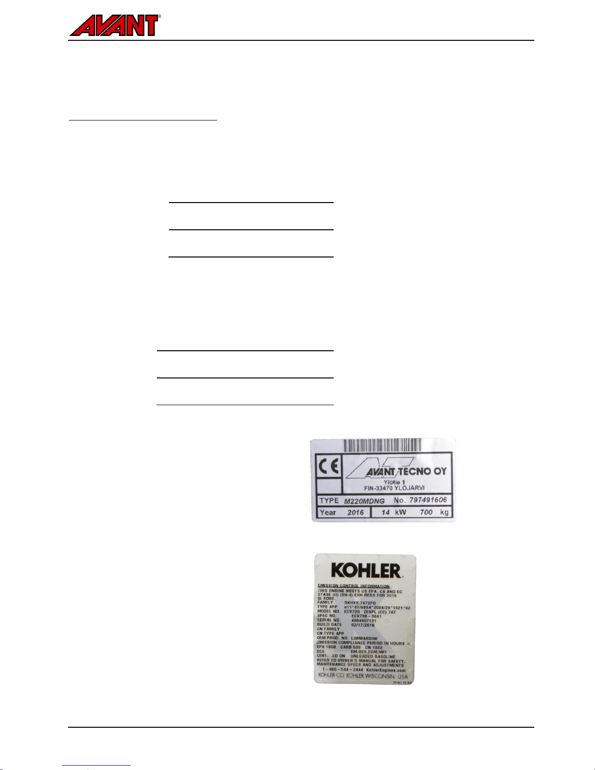
Identification of the loader
Write down the identification information of your loader in the following fields, it facilitates ordering of spare parts
etc.
1.
Loader model
2.
Loader serial no.
3.
Engine serial no.
Serial number of the loader is printed on the type plate, which also indicates the loader model. Location of engine
serial number can be found in the Operators Manual of the engine.
Dealer:
Contact information
Loader identification
Loader identification plate is located near the left
knee of the driver.
Engine identification
Engine identification plate is visible under the
seat on the side of the engine. Further details are
shown in the engine operator’s manual.
Avant 220/225
18
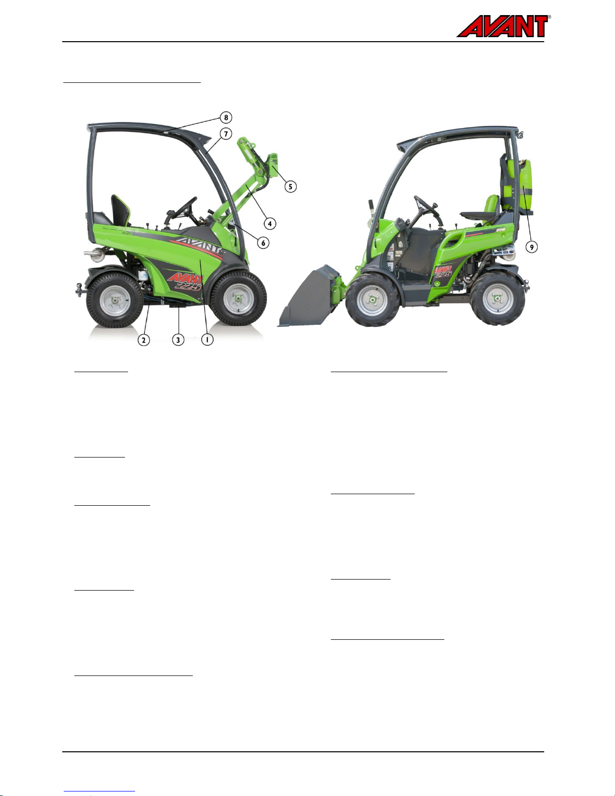
.
Main parts of the loader
Following picture shows the main parts of the loader:
.
..
1. Front frame
On the front frame are mounted: driver’s seat,
operating controls, engine with accessories, battery,
hydraulic components, fuel tank, oil tank, front
wheels with hydraulic motors, and loader boom with
attachment coupling plate.
2. Back frame
On the back frame are mounted: rear wheels with
hydraulic motors, counterweights, trailer coupling.
3. Articulation joint
Articulation joint connects the front and back frame.
The loader is steered hydraulically by the steering
cylinder which is mounted between the front and
back frames. Hydraulic hoses and electric wires are
conducted through the articulation joint.
4. Loader boom
Loader boom is mounted on the front frame and is
controlled with control lever from the driver's seat.
The attachment coupling plate is mounted at the end
of the boom. The boom is fitted with a mechanical
parallel linkage.
5. Attachment coupling plate
Attachments are mounted on the attachment
coupling plate. The locking pins on the plate are
manually operated type.
6. Auxiliary hydraulics outlet
The hydraulic hoses of hydraulically operated
attachments are mounted on this outlet. The outlet is
equipped with the multi connector quick coupling
system and is double acting: it has two pressure
lines and one tank line, see page 55. If the loader is
equipped with the optional Attachment control switch
pack, its electric socket is integrated in the multi
connector.
7. ROPS safety frame
ROPS frame (Roll-over protective structure)
complies with the standard ISO 3471:1994 with
Amendment 1:1997 and Technical Corrigendum
1:2000 for a maximum machine configuration mass
of 1200 kg.
8. FOPS canopy
FOPS canopy (Falling objects protective structure)
mounts on the ROPS. It meets the ISO 3449:2005
(1365 J) criteria.
9. LPG Gas bottle (225LPG)
Vertically installed gas bottle, from which gas is
drawn in vapour form. See page 26.

Avant 220/225
19
.
Signs and decals
Shown in the figure below and listed on the following page are the labels and markings, which must be visible on
the equipment. Replace any warning label which has become unclear, or has detached completely. New labels are
available via your retailer or contact information provided on the cover.
Before applying a new decal, clean the surface from dirt, dust, grease, or other material. Peel small portion of the
decal backing paper and apply exposed adhesive to cleaned surface, aligning the decal properly. Peel rest of
backing paper and press with hands to smooth out the decal.
The warning labels contain important safety information and they help to identify and
remember the hazards related to the equipment.
Make sure that the following signs and decals are clean, undamaged and readable. If any
of these decals is missing or is unreadable it should be replaced without delay. Ask for
new decals from your local Avant dealer.

Avant 220/225
20
.
Table 2 - List of safety labels and markings on the machine (continued on following pages)
Label
Location
Product code
1
Dashboard,
around/ behind
steering wheel
A420546
Symbol
Safety message
a b
WARNING
a Wrong use, misuse, or careless use can cause hazards that
could be prevented with following the instructions properly.
Read all instructions carefully before operating the loader.
b Lowering of loader boom can crush, causing death or
serious injury.
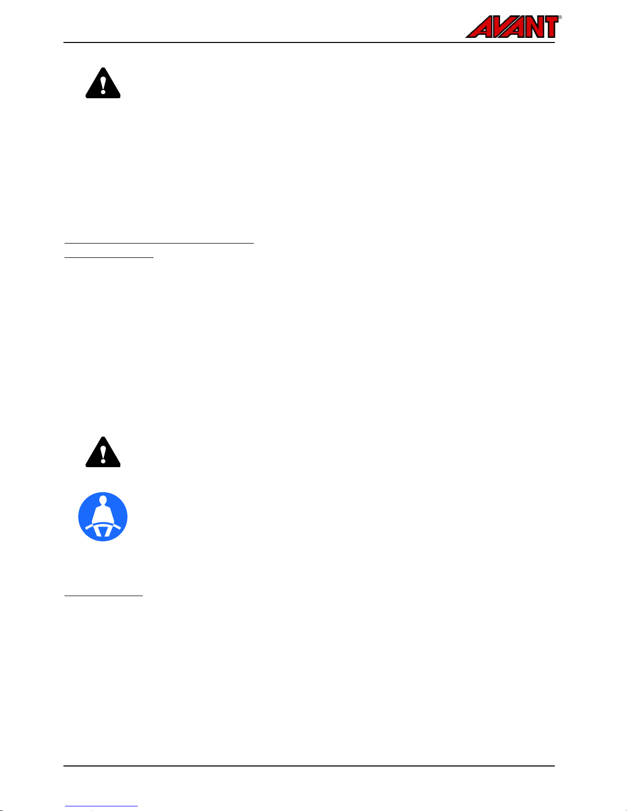
Keep out from the danger zone of the machine.
c Risk of falling of persons and getting run over.
Never carry passengers with the loader or its attachments.
d High pressure fluid injection hazard.
Never use hands to search for leaks.
e Risk of dropping of attachment.
Make sure both locking pins are locked.
f Risk of getting crushed by moving loader.
Apply parking brake and lower attachment on the ground.
Make sure loader will not move when leaving the driver's
seat.
c d
e f
Avant 220/225
21
.
Symbol
Safety message
g h
g
Always wear seat belt.
h
Wear hearing protection. Depending on use, noise level at
driver's seat and around the loader and its attachments may
be high enough to cause hearing damage.
i j
i
Wear protective gloves with good grip.
j
Wear safety boots with good grip and feet protection.
Label
Location
Product
code
Safety message
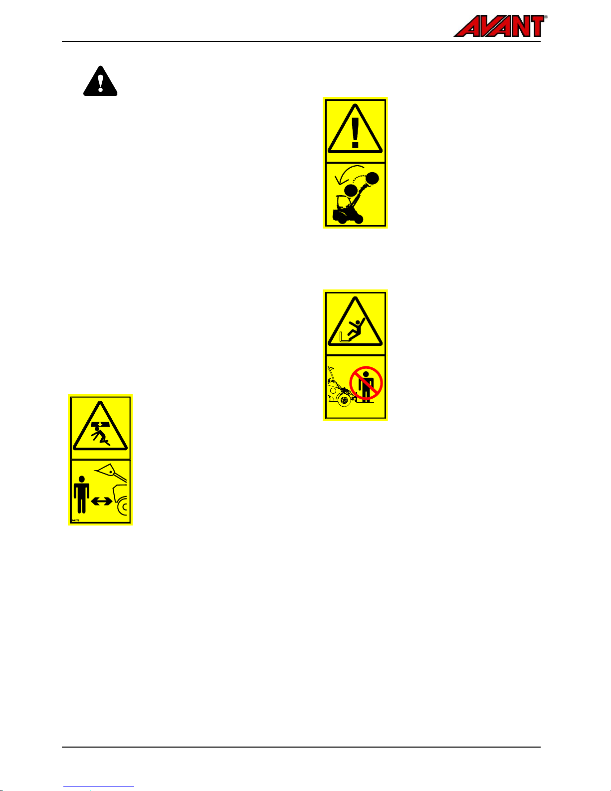
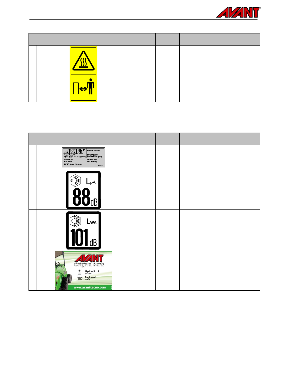
2
Boom, on
both sides
A417273
(2 pcs)
DANGER
Lowering of loader boom can crush,
causing death or serious injury.
Keep out from the danger zone of the
machine.
3
Panel
below
steering
wheel
A421187
WARNING
Risk of rolling over - Keep loads close
to ground, drive slow when carrying
load.
Always use seat belt.
WARNING
Risk of tipping over (front direction) -
Keep load close to ground, drive
slowly.
Read operator's manual carefully.
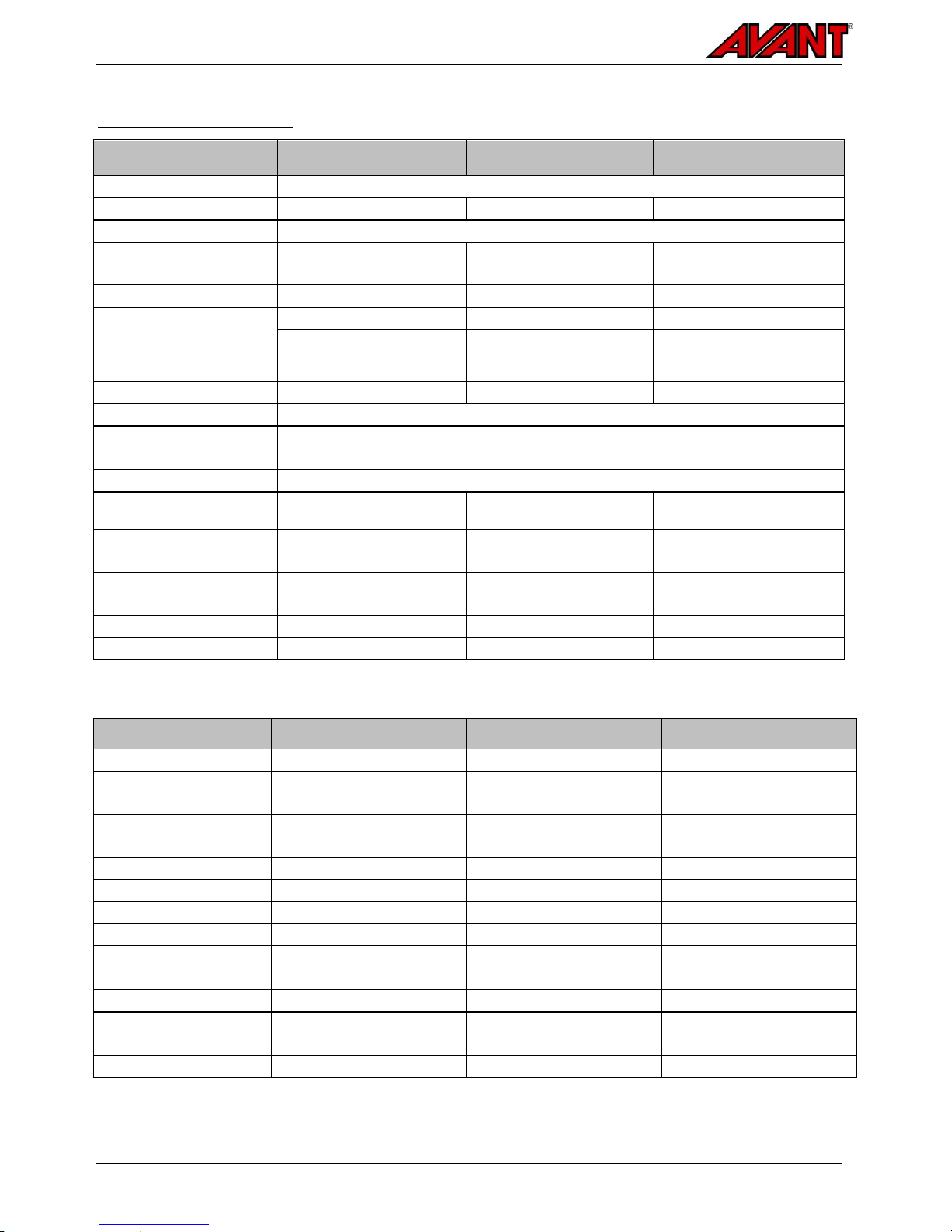
4
On engine
A417270
WARNING
Risk of burns - Extremely hot surfaces.
Keep clear.
Allow loader to cool completely before
maintenance.
Avant 220/225
22
.
Label
Location
Product
code
Safety message
5
Rear
ROPS
posts
A414244
(2 pcs)
WARNING
Hot exhaust - Keep clear.
Exhaust gases and all parts of exhaust
system become extremely hot during
use.
Stay clear of any exhaust part until
engine is allowed to cool, avoid also
reversing or leaving loader near
flammable materials.
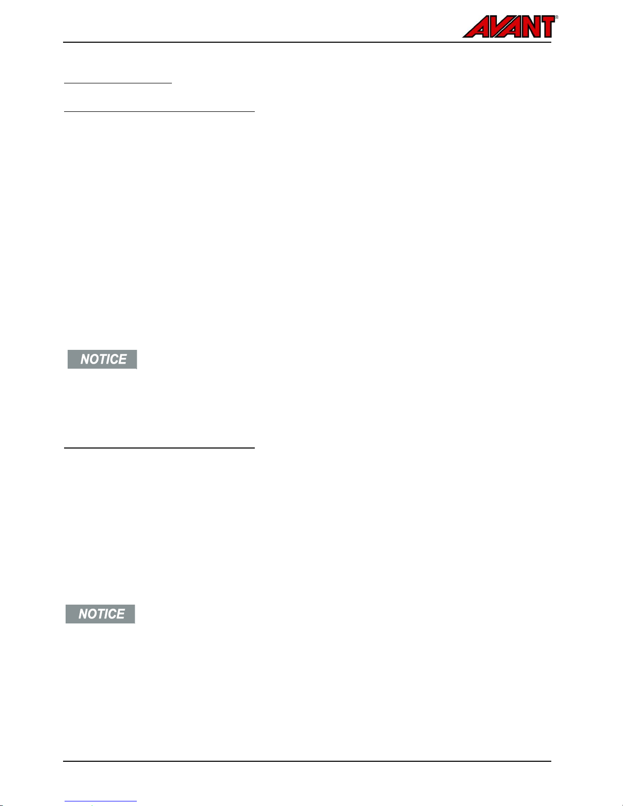
Table 3 - Information labels
Label
Location
Product
code
Message
6
ROPS
frame
A420726
ROPS/FOPS Approval
7
Right
panel near
driver's
seat
A43600
Sound pressure level 88 dB(A) at
driver's seat
8
Right
panel near
driver's
seat
A411047
Sound power level 101 dB(A)
2000/14/EC
9
Front
panel
below
driver's
seat
A415780
Correct type of hydraulic and engine oil

Avant 220/225
23
.
Technical specifications
Dimensions
General dimensions
Length
1910 mm
225LPG: 1940 mm
Width
1025 mm (with standard tyres)
995 mm (see page 25)
Height
1880 mm (with standard tyres)
Mass (empty)
220
225
225 LPG
700 kg
700 kg
760 kg
Tyres
Standard:
20 x 8.00-10 TR /
20 x 8.00-10 GR
Lifting height
1400 mm
Max reach
810 mm
Turning radius,
inside/outside
910 mm / 2220 mm
Ground clearance
150 mm
Drive speed and pulling force
Tyre
Drive
speed
Pulling
force
220
20 x 8.00-10 TR
10 km/h
6200 N
20 x 8.00-10 GR
10 km/h
6200 N
225
225
LPG
20 x 8.00-10 TR
10 km/h
6400 N
20 x 8.00-10 GR
10 km/h
6400 N
Height and Width
Tyre
Height
Width
20 x 8.00-10 TR
1880 mm
995 mm
20 x 8.00-10 GR
1880 mm
995 mm
.
..
.
..
.
..
.
..
.
..
.
..
.
..
Avant 220/225
24
.
General specifications
220
225
225LPG
Category
Earth-moving machinery / Loader/ Compact loader EN ISO 6165
Product code
A21675
A21687
A21698
Drive system
Hydrostatic 4WD
Tipping load ISO 14397-1
(see also page 28)
320 kg
320 kg
350 kg
Rated operating capacity
175 kg
175 kg
200 kg
Auxiliary hydraulics
*See also page 27
Max 20,0 MPa (200 bar)
Max 20,0 MPa (200 bar)
Max 20,0 MPa (200 bar)
Max flow
Front: 30 l/min
Rear: 7 l/min
Max flow
Front: 43 l/min
Rear: 7 l/min
Max flow
Front: 43 l/min
Rear: 7 l/min
Hydraulic pumps 2 2
2
Auxiliary hydraulics
Standard: Faster multiconnector system on front
Attachment coupling
Avant quick coupling attachment plate
Hydraulic oil capacity
23 l
Hydraulic oil type
ISO VG 46, mineral oil only
Fuel tank capacity
14 l
14 l
Steel propane tank
See page 26
Sound pressure level
2000/14/EC Lp, ISO 6396
101 dB(A)
101 dB(A)
100 dB(A)
Sound power level
2000/14/EC Lp, ISO 6395
88 dB(A)
88 dB(A)
88 dB(A)
Hand-arm vibration, total
< 2,5 m/s2
< 2,5 m/s2
< 2,5 m/s2
Whole-body vibration, max.
< 0,5 m/s2
< 0,5 m/s2
< 0,5 m/s2
Engine
Model
220
225
225LPG
Engine
Kohler CV640
Kohler ECV730 EFI
Kohler PCV740 EFI
Engine max output
14,9 kW (20,5 hp),
3600 rpm
18,6 kW (25 hp)
3600 rpm
17,9 kW (24 hp)
3600 rpm
Operating principle:
4-stroke V2, OHV
4-stroke V2, OHV
Electronic fuel injection
4-stroke V2, OHV
Electronic fuel injection
Fuel (see page 26)
Gasoline
Gasoline
Propane (Propane/Butane)
Cooling
Air
Air
Air
Starting system
Electric
Electric
Electric
Displacement
674 cm3
747 cm3
747 cm3
Bore * stroke
77*67 mm
83*69 mm
83*69 mm
Engine oil
wet, oil pump, filter
wet, oil pump, filter
wet, oil pump, filter
Oil capacity (refill)
1.9 l
1.6-1.9 l
1.6-1.9 l
Engine oil:
SAE 10W-30
API CF-4/SG
SAE 10W-30
API CF-4/SG
SAE 10W-30
API CF-4/SG
Valve clearance
Hydraulic tappet
Hydraulic tappet
Hydraulic tappet

Avant 220/225
25
.
Tyres
The loader can be equipped with different type of
tyres for different operating conditions. Grass pattern
(GR) tyres will damage the ground surface less than
tractor (TR) tyres, but provide less traction.
Tyre
Tread
pattern
Code
Fill
pressure
Max
pressure
20 x 8.00-10
TR
66231
2,3 bar
2,9 bar
20 x 8.00-10
GR
66252
2,3 bar
2,9 bar
For the best stability and controllability, always use
the largest tyres possible.
Use only tyres and rims that meet the original
specifications and dimensions to avoid potential
issues with load capacity, tyre size, or bearing load
on drive motors. Special tyres, such as studded
wheels may also be available. Consult your dealer
for further information.
Snow chains will not fit and are not available for the
loader.
WARNING
Risk of tipping over - Make sure
tyres are not damaged. Loss of
tyre pressure can cause loader to
tip over. Make sure there are no
visible damages on tyres. Keep
tyre pressure within
recommendations.
Wheel spacers
The wheels are fitted with spacers that increase the
width of the loader for better stability. In special
cases where the width of the loader is restricted, the
wheel spacers can be removed. Remove only if
operating on flat areas. The spacers A44337 are 15
mm thick.
WARNING
Wheel spacers improve the lateral
stability of the loader. Do not
remove the wheel spacers unless
operating the loader on flat areas,
where the total width of the loader
must be reduced to as narrow as
possible.
Use only spacers recommended by
the manufacturer. Too thick spacers
may damage the hydraulic motors.
Contact your Avant dealer for more
information.
Wheel weights (optional extra)
Extra wheel weights can be fitted to improve stability
of the loader. If fitting only two weights, they should
be fitted to rear wheels.
The 14 kg weights are installed to wheel rim with two
special bolts included in the kit as shown below.
Avant 220/225
26
.
Fuel requirements
Gasoline requirements (220/225)
Gasoline fuel must meet the following
requirements:
Clean, fresh, unleaded gasoline from a clean
container. Do not use gasoline older than 30
days.
Minimum octane rating:
EU: Min 90 (RON)
North America: 87 (R+M)/2
Bio fuel mixed with ethanol (max 10%) can be
used.
Gasoline blend with max 15% MTBE additive by
volume (Methyl Tertiary Butyl Ether) is approved.
Do not add oil to gasoline.
E15, E20 and E85 are not
approved for use with the engine
in the loader. Effects of old, stale
or contaminated fuel are not
covered by warranty.
LPG gas requirements (225LPG)
Avant 225LPG is intended to operate with gas that
flows as vapour from the bottle, not liquid. Regular,
commonly available gas bottles that are also used for
i.e. heating, grilling etc. and used in vertical position
are correct type of gas bottles.
NOTE: The Avant 525LPG, another Avant loader
model, uses different type of gas system with
external vaporizer. This means that the gas bottles
are not interchangeable between these two loader
models.
The Avant 225LPG is intended to be
used with gas bottles that are used in
upright position and supply gas in
vapour form, not liquid.
Make sure to use correct type of gas
bottles, contact your local dealer for
more information.
The exact type of gas bottle will depend on the area
where the loader is used, but the following general
instructions and requirements apply.
When replacing a gas bottle, take the following into
account:
The loader engine is certified to operate with
commercial propane that complies with USA
standard GPA STD 2140. This standard
specifies that the maximum amount of butane is
limited to a low level. If you operate the loader in
cold climate, use LPG gas that is only propane.
Bottle must supply LPG in vapor form, not liquid.
Hose coupling must be threaded fitting, not any
quick coupling type. Hose threading must match
perfectly the hose threads. See page 27 for
standard hose fittings and typical, available fitting
options.
Overpressure valve must be fitted and in
functioning condition. Bottle itself and its valve
must be inspected periodically by qualified
technician. With bottles that are exchanged to
full ones, this is usually managed by businesses
offering exchange bottle service.
Physical dimensions of the bottle must be within
the following limits:
300 mm in diameter
700 mm height
Stainless steel, steel, and aluminium bottle
absorb heat the best. Do not use plastic /
composite bottle, they will not absorb heat from
surrounding air effectively
Larger bottles absorb more heat than smaller
ones.

Avant 220/225
27
.
Gas hose fittings
The hose connecting the gas bottle has fitting that
might need to be replaced, if planning to operate with
another type of gas bottle. If different type of fitting is
necessary, contact your local Avant dealer. Use only
fittings that are of correct size and thread type. Make
sure the fittings seal correctly. Do a gas leak test
after you have installed all fittings, refer to page
71.
.
..
Connects
Thread
Gas hose to pressure
regulator
UNF 5/8"-18 SAE 45º
Gas hose to gas bottle
R3/8"
Standard adapter for
gas bottle
Adapter RU 3/8” LH ->
DIN 477 W21,8 x
1/14" LH O-ring
.
..
Engine oil requirements
Use only high quality engine oil with the viscosity
rating recommended by the engine manufacturer
with API service class SJ or higher. See also Kohler
Operator's Manual.
In cold conditions use high quality multi grade oil.
Auxiliary hydraulics oil flow
The graph below shows auxiliary hydraulics output
flow at different engine rpm levels.
Some attachment may work optimally at certain flow
level, use the graph to estimate correct engine rpm
setting.
Maximum auxiliary hydraulics oil
flow can not be used with all
attachments. Check correct engine
rpm for the attachment with the
help of this graph and the
Operator's Manual of the
attachment. Attachment may get
damaged, run too fast, or it may be
difficult to control precisely when
oil flow is too high.

Avant 220/225
28
.
Tipping load
Tipping load is the load at which the rear tyres lose
contact with the ground (tipping forward). Tipping
load is influenced by several factors:
The total load on the loader boom
(attachment weight and load combined)
The distance of the load from the front tyres
Straight or articulated position of the loader
frame
Levelness of the ground
Installed counterweights
Driver presence
Movements of the loader and the load
The lifting capacity of the loader is
limited by the possibility of tipping
around the front axle.
The operator must pay attention to
safe operating conditions
whenever handling loads.
Load diagram
With the diagram the load handling capability of the
loader can be evaluated, according to the distance
between the centre of gravity of the load and the
front axle of the loader. The diagram represents the
forward stability only, it does not refer to maximum
available lift force.
The load diagram below shows the tipping loads on a
level surface:
a) Tipping load with the loader frame in straight
position.
b) Tipping load with the loader frame in
maximum articulation.
ROC (Rate operating capacity), defined as
60 % of tipping load for pallet forks.
The lifting capacity and the stability of the loader are
at the best, when:
the loader frame is kept straight
the centre of gravity of the load is as close to the
loader as possible
counterweights are fitted to the loader
swinging of the load is prevented and all controls
are used in a calm and careful manner
Example: If the centre of gravity of the load is 840
mm in front of the front axle (400 mm from the pallet
forks at ground level), the tipping load is about 390
kg with a driver weighing 75 kg and with the
articulated frame turned to max articulation.
If the driver leaves the machine, tipping
and max. loads are reduced
respectively.
The indicated load is the maximum load
that can be loaded on pallet forks and
the machine will not tip over, i.e. the
weight of the pallet fork attachment (95
kg) is taken into account.
WARNING
Avoid overloading the loader know the load and lifting
capacity of the loader. The
diagram is valid only on firm
and level ground, with the
conditions listed above.

Avant 220/225
29
.
Rated operating capacity
To determine how much the loader can handle
safely, a table of the tipping load and a calculated
Rated Operating Capacity (ROC) is shown in the
adjacent label. The label is also visible from the
driver's seat.
Rated operating capacity depends on type of use of
the loader:
In bucket and general application the rated
operating capacity is 50% of tipping load
In pallet fork application the rated operating
capacity is 60% of tipping load
The information shown in the table is the worst case
minimum load, with the conditions listed below.
Actual lifting capacity could be significantly higher, or
it may be lower, depending on terrain conditions,
available lifting force, and load distribution. Adding or
removing counterweights will affect the indicated
ROC.
The ROC table is valid, when:
The ground is firm and level
Loader is stationary or driven max 2 km/h,
with smooth and slow control movements
Driver 75 kg is seated on the driver’s seat
Load is distributed evenly on pallet forks,
with the load centre of gravity at 400 mm
from the vertical part of pallet fork arms. The
weight of the fork attachment is taken into
account in the indicated load values.
Rated operating capacity
Different loader configurations, rows in the label:
1. Loader frame in straight position, standard
counterweight fitted
2. Loader frame in fully articulated position,
standard counterweight fitted
Different positions of the loader boom, columns
in the label:
1. Maximum tipping load, stability when lifting
load just off the ground
2. Boom lifted to horizontal position (least
stable position)
3. Rated operating capacity in pallet fork
application

Avant 220/225
30
Controls of the Loader
Following picture shows the location of operating controls. The location and function of controls may be slightly
different in different models, see following pages.
Reference
Page
1.
Multi-Function Display
Ignition switch
12 V outlet (max 15 A)
31
41
35
2.
Signal horn
3.
Work light switch
4.
Seat heater switch
36
5.
Hand throttle lever
33
6
Control lever of boom and bucket
32
7.
Auxiliary hydraulics control lever
32
8.
Choke knob (220 only)
41
9.
Switches, see table below
10.
Rear auxiliary hydraulics control
lever (optional extra)
35
11.
Multi connector for attachment
coupling
54
12.
Hydraulic oil filling and dipstick
64
13.
Attachment control switch pack
33
.
..
Switches on the panel
Emergency
blinker
(option)
Warning
beacon
(option)
Windscreen
wiper and
washer (CAB
L option)
Extra work
lights on the
ROPS frame,
2 front, 1 rear
(option)
Controls in the footwell
a Parking brake lever
b Drive pedal, left: drive backward
c Drive pedal, right: drive forward
See correct operation of the drive pedals on page
42.
Parking brake lever
The loader is equipped with mechanical parking
brake that locks the front wheels. When locking or
unlocking the brake, turn the steering wheel sharply
or press gently on the drive pedals, so that the
locking pins lock or unlock.
Lock: turn left and down into locking position.
Release: turn right and up to release parking
brake.

Avant 220/225
31
.
Dashboard
The multi-function display includes indicator related to features on the loader and the engine, a fuel level metre,
and an hour metre. The display is backlit whenever standard work lights or the road traffic lights are switched on.
The hour metre runs whenever the engine is running.
Indicator lights
Symbol
Colour
Remarks
1
Red
Low engine oil pressure
Stop engine immediately. Low
oil pressure can cause severe
engine damage. Check first if
low pressure is caused by low
engine oil level.
2
Red
Charge indicator
Battery discharging - limited
electric power supply of the
loader may not allow to use all
electric features simultaneously.
If indicator is lit, switch off
electric devices, or increase
engine RPM for higher charging
current.
3
Red
Temperature indicator
Not active on 200 series
loaders. If lit during operation,
light refers to too high hydraulic
oil temperature, allow to cool.
4
Red
MIL (225 only)
Engine Malfunction Indicator
Light, see page 72.
5
Yellow
Fuel level low
(not in use in 225LPG)
See page 46.
6
Blue
High beam headlights on
Road traffic light kit only
7
Red
Hydraulic oil cooler fan fuse
Hydraulic oil cooler malfunction.
See page 73
Symbol
Colour
Remarks
8
Green
Turn signal indicator
Road traffic light kit only
9
Green
Seat heater on
Suspension seat only
The charge indicator lamp may
remain lit after starting the engine.
After running the engine with higher
RPM, the light will turn off.
Engine oil pressure and charge
indicator lights should light up for a
brief moment when ignition key is
turned to ON position. If not, repair
before using the loader.

Avant 220/225
32
.
Control of loader boom, auxiliary hydraulics and other functions
Most of the functions of the loader are controlled with the controls at the right side of the operator: Boom and
bucket movements, auxiliary hydraulics (attachments), engine revs etc. , depending on loader model. Following
paragraphs show the different functions.
1. Control lever of boom and bucket
The loader boom and bucket are controlled with the multi-function lever sideways (tilt) and back & forward (boom
up & down).
Pull backward to lift the
boom
Push forward to lower the
boom
Push left to raise the tip of
the bucket (filling)
Push right to lower the tip of
the bucket (emptying)
2. Control lever of auxiliary hydraulics (hydraulically operated attachments)
Hydraulically operated attachments are connected to the loader using the multi connector system, for more
information see page 55.
Operation directions depend on the attachment used.
When using an attachment for the first time, carefully
move the lever to test and check the operating direction
of the attachment.
For continuous operation of rotating attachments, turn to
direction 1 and turn to locking position.
If operating the buttons of the electric joystick, this lever will
not move on 200 series loaders. Either the lever or the
buttons can be used to control the attachment as needed.
When you operate attachments that require continuous flow,
such as attachments with hydraulic motors, it is important to
have the control lever in fully engaged position. If the control
valve is not fully open, restricting the flow of hydraulic oil,
hydraulic system may overheat quickly.
If necessary, adjust the locking plate so that the lever is
locked to fully open position.

Avant 220/225
33
3. Joystick - 6 function (optional
extra)
If the loader is equipped with the optional 6 function
joystick, the auxiliary hydraulics can be controlled
with electric buttons on the joystick:
Push and hold either button to
operate hydraulic feature of the
attachment. While holding a
button, the manual control lever
also moves to corresponding
direction.
The operation of the buttons
depends on the attachment,
see Operator's Manual of the
attachment.
Release buttons to stop.
Make sure the manual control
lever is not locked when
operating electric joystick.
CAUTION
Avoid abrupt movements of an
attachment - Use electric
buttons with caution. When you
use certain attachments with the
electric joystick buttons, the
attachments can move abruptly.
This can cause falling of material
from the attachment, loss of
stability, or damage to attachment.
4. Attachment control switch pack
(optional extra)
If your loader is equipped with the
optional attachment control switch
pack, the electric functions of an
attachment can be controlled with
the extra buttons fitted on the
joystick.
Check the operator's manual of the attachment to
see how to control each attachment.
When the loader is equipped with the Attachment
control switch pack, the Multi connector ( see page
55) includes also an electric socket, so that the
hydraulic hoses and the electric cable of an
attachment with electric function(s) can be coupled
simultaneously with the multi connector system.
Hand throttle lever
The engine running speed is controlled with the hand
throttle lever.
Push forward to increase engine rpm
Pull backward to reduce engine rpm
The engine rpm affects the driving speed and can be
used to control driving speed in combination with the
drive pedals.
Engine speed also has an effect on the speed of a
hydraulically driven attachment; the more throttle the
faster the attachment operates. Make sure not to
exceed max. allowed oil flow of the attachment, see
Auxiliary hydraulics oil flow on page 27.

Avant 220/225
34
.
Engine compartment
To access the engine, unlock the seat base by
pulling the lever under the seat forward and tilt the
seat forward:
1.
2.
WARNING
Allow engine to cool before
accessing the engine. Engine and
exhaust parts may be extremely
hot after use.
The adjacent warning label is
located on the engine. Hot areas
include the engine in general, and
especially its exhaust pipe(s) and
surrounding areas.
CAUTION
Be careful when handling the seat
base and keep hands and fingers
clear when lifting or lowering uncontrolled movements may
crush or cut.
WARNING
Shut off engine and allow it to cool
before accessing engine
compartment. Moving or rotating
parts may injure.
Battery disconnect switch
The loader is equipped with a battery disconnect
switch (main switch). The switch is located under the
driver's seat in the engine compartment, on the left
hand side.
Battery disconnect switch cuts the current between
battery and the rest of the electric system. Always
switch off main current when the loader is not used
for a longer period of time in order that the battery
doesn't get empty, or when servicing the machine.
Trailer coupling
The loader is equipped with a 50 mm ball hitch type
trailer coupling for towing of light trailers.
Max. allowed vertical load 2000 N
Maximum towing load is 3000 N.

Avant 220/225
35
DANGER
Overload on the trailer coupling
may cause loss of control. Tow
only light garden trailers. Make
sure that the weight on the trailer is
distributed correctly so that the
trailer cannot cause an upward
lifting force on the trailer coupling.
Rear auxiliary hydraulics outlet
(option)
In addition to the standard auxiliary hydraulics outlet,
the loader can be equipped with a double acting
extra outlet at the rear of the machine. The couplers
are conventional type quick couplers, fitted near the
trailer coupling.
The extra outlet is controlled with its own, 2
direction control lever on the right from the
driver's seat.
Release the lever to neutral position to stop the
attachment.
Test the operation of the attachment after each
time it is coupled to the loader. The quick
couplings can be coupled in a way that reverses
the function of the control lever.
Both the front and rear hydraulics can be
operated simultaneously.
Keep the couplings clean and use their
protective covers.
To connect or disconnect rear hydraulic coupling,
see page .
Engine heater (option)
The loader can be equipped, as an option, with an
engine heater for easier starting in cold outside
temperatures. Engine heater socket (220V-240V) is
on the right side in the rear of the machine.
Electric 12 V outlet
When operating attachments with electric features,
the electric harness of the attachment is connected
to the 12 volt outlet on the dashboard. The standard
type outlet is powered when ignition is switched on.
Maximum current: 10 A.
Spark arrestor (option)
A spark arrestor is a device that prevents emissions
of flammable debris from the engine exhaust. If
operating the loader in areas with risk of forest fire, a
spark arrestor must be fitted. A certified type of spark
arrestor may be required by local laws.
When fitting the spark arrestor, make sure it is
secured around the exhaust pipe and will not
become loose due to vibration or heat stresses.
Clean the spark arrestor with metallic brush if
necessary.
Reverse buzzer (option)
A reverse buzzer gives an audible signal whenever
reversing with the loader. This alarms others of an
approaching machine and thus improves safety.

Avant 220/225
36
.
Seat - Seat belt and seat adjustments
WARNING
The seating capacity of the loader
is one person only. Never carry
passengers on part of the loader or
with any attachment.
Always use seat belt while driving. Clean the seat
belt regularly with a sponge, warm water, and soap.
Use compressed air to clean the buckle.
Replace the seat belt if any damage is seen, or if the
seat belt is exposed to high load or chemicals.
Seat adjustments
Make sure that the seat is properly adjusted for easy
reach to the operating controls and to keep vibrations
transmitted by the seat at minimum. Long term
exposure to vibrations may cause health effects.
Also, as far as possible, keep the operating terrain in
good condition to minimise vibrations.
Standard seat
The distance of the seat from the steering wheel can
be adjusted with the lever which is located under the
front edge of the seat.
Suspension seat (option)
The suspension seat has the following adjustments:
1. Seat position
The distance of the seat from the steering
wheel can be adjusted with the lever which is
located under the front edge of the seat
2. Arm rest angle adjustment
The angle of the arm rest can be adjusted by
turning the roller under the arm rest
Adjust the arm rest to position which allows
to use controls of the loader comfortably
while keeping arm on the arm rest.
3. Suspension adjustment
By turning the knob counterclockwise
suspension gets harder, by turning it
clockwise the suspension gets softer
4. Angle of the back rest
The angle of the back rest can be adjusted
by pulling the lever
Seat heater
The suspension seat is equipped with an electric
seat heater. Seat heater switch is located by the
steering column and indicator light is on the
multi-function display.

Avant 220/225
37
.
Lights
Work lights
The loader is equipped with standard work lights at
the front of the loader, which are controlled with a
switch near the ignition switch.
If the loader is equipped with the optional road traffic
light kit, the standard work lights are replaced with
road headlights.
Extra work light kit (option)
The loader can be equipped with extra work lights,
making it easier to work in low light. The lights are
operated with the switch on the control panel ( see
page 30).
Headlight, beacon, blinker & reflector
kit (option)
This optional equipment enables road traffic
registration in certain countries. Requirements for
road traffic use vary in different countries, please
consult your local AVANT dealer.
Warning beacon (option)
The beacon can be removed quickly by loosening its
retaining screw and then by pulling the beacon out.
Place the protective seal on the beacon stand to
prevent water entering and damaging the
connectors. Handle beacon with care. The beacon is
sealed and its inner components cannot be replaced
or repaired by user.
Beacon includes high-voltage
components. Do not use or repair
damaged beacon, replace with new
one.
Light control switch (road traffic light
kit)
Loaders fitted with road traffic light kit have a
multi-function control switch fitted to the steering
column.
The switch has the following controls:
Headlights
High beam lights
Signal horn (duplicate switch, both the switch on
near the ignition key and switch on multi-function
control are connected)
Indicator turn lights

Avant 220/225
38
.
CAB L (optional extra)
The Avant 220/225/225LPG can be equipped, as an
option, with cab L. Shown in this chapter are the
controls and features that differ from the standard
ROPS model.
Windscreen washer and wiper
On machines with cab L, the windscreen washer is
operated with a switch on the left to the steering
wheel. The switch has the following functions:
2.
1.
0.
Spray washer fluid
Continuous operation
Off
The windscreen washer fluid tank is located near the
left knee of the driver while seated on driver's seat.
Cab Safety
Make sure visibility from the cab is adequate. Keep
all window panels clean and clear of snow, ice, etc.
Familiarise yourself with the special drive features
and space needs of this articulated loader, equipped
with cab, on a flat, even and open place.
Remember that, when turning, the cab extends
beyond the turning radius of the wheels. This should
be taken into consideration especially when driving in
confined spaces, in order that the rear of the cab will
not get damaged.
In case the normal
opening on the left side of
the loader is blocked, the
windscreen can be used
as an emergency exit.
If necessary, the
windscreen can be broken
with the emergency
hammer located in the
cab.

Avant 220/225
39
Operating instructions
.
..
Always remember – safety first. Test all the functions of the loader at an open and safe
place. Make sure that there are no persons in the operating area of the machine and the
danger zone of the attachment.
.
..
DANGER
Careless operation can injure you or bystanders - Keep the loader under control at
all times. Operating a powerful loader and its attachments requires the full attention of
the operator. Do not perform distractive actions while operating, such as using mobile
devices.
.
..
WARNING
Pay attention to other machines and persons that are moving in the area. Make sure that
there are no persons in the danger zone of the loader and the attachment. The danger
zone of the loader covers the reach area of the loader boom, the turning area on the side
and in the front and rear of the loader. Always put down the load when leaving the
machine – the loader is not designed to stay with the loader boom and load lifted. Learn
how to operate the loader in a safe place.
.
..

Avant 220/225
40
.
Starting the engine
Before starting the engine do the daily checks, (see
"Daily inspections" on page 60). Adjust the seat
and mirrors (if fitted) so that you have a good
working position and unrestricted field of vision from
the driver’s seat. Check that all controls function
correctly. See to it that the operating area is safe.
Read and follow operating and safety instructions.
WARNING
If auxiliary hydraulics is switched
on during starting and there is a
hydraulically operated attachment
on the machine, the attachment
can move suddenly and cause a
dangerous situation.
Make sure that the
auxiliary hydraulics control
lever is in neutral position
during starting.
Do not actuate the
auxiliary hydraulics control
buttons on the joystick (if
fitted when) starting.
WARNING
Prevent unintended movements
of the loader. Keep hands and
feet away from other controls of
the loader while starting.
Do not start the loader in enclosed space - Exhaust
emissions can kill within minutes
DANGER
Exhaust emissions are toxic in
concentrated amounts. Do not
operate the loader in enclosed
spaces or insufficiently ventilated
spaces, i.e. open garage door first.
.
..
Ignition key
.
..
Open/close LPG bottle
Exact instructions of how to open or close the
manual shut off valve of the LPG bottle depend on
the manufacturer of the bottle.
Open the LPG bottle just before starting of the
loader.
Open valve fully, usually by turning 2-3
rounds counter-clockwise.
Keep the shut off valve closed whenever not
actively using the loader.
Do not overtighten.
Close the gas valve carefully, do not
overtighten the valve. Do not open the
valve more than necessary, typically
max. 2-3 rounds, depending on gas
bottle type. Gas bottle valve and the
gas hose normally tighten when
turning clockwise. See markings on
the bottle valve.

Avant 220/225
41
To start the engine:
1. Perform daily checks (see Maintenance &
Service on page 57)
2. Turn the battery disconnect switch to ON
Open gas bottle valve (225LPG only)
3. Move the hand throttle lever to idle position
Cold start, 220 only: Pull choke knob halfway
or fully up
4. Make sure that auxiliary hydraulics is switched
off (lever in neutral position), see page 32. Do
not press on the drive pedals.
5. Turn the ignition key to the right, to ON
position. Signal lamps on the multi-function
display will light up briefly for self-check. Oil
pressure and charge indicator lights will remain
lit.
6. Turn the ignition key further to the right, to start
position and hold until engine starts. Return
key to ON position in controlled manner.
220: Push choke knob slightly down once the
engine has started. Depending on
temperature, the knob may be pushed fully
down immediately after start or after warming
up for a moment first. Keep choke knob in full
down position in normal use.
.
..
Do not actuate the starter for more
than 10 seconds at a time. If the
engine does not start, wait for one
minute before repeating attempt. If
the engine does not start after a
few attempts, or runs poorly, See
troubleshoot on page 74 and the
engine owner’s manual.
After starting:
Allow the engine to warm up and
engine oil to circulate in the engine
for a moment before loading the
engine or increasing engine revs.
.
..
Make sure that all the warning
lights on the control panel are off
when the engine is running. If the
engine does not start after a few
attempts, or runs poorly, See
troubleshoot on page 74.
Stopping the engine (Safe stopping
procedure)
1. Lower the boom completely down. Place
attachment firmly on the ground, engage
parking brake, stop the attachment (move
auxiliary hydraulics control lever to neutral
position, see page 32), set engine revs to
idle.
2. Stop the engine by turning the ignition key to
the OFF position (to the left)
3. Release auxiliary hydraulics pressure (see
page 56).
4. Prevent unauthorised use of the loader. Take
off the ignition switch and turn the power off
with the battery disconnect switch.
Stop the engine as soon as possible,
if any of the following symptoms is
observed. Find out the cause before
restarting.
The oil pressure warning light, or malfunction
indication light turns on during operation.
Engine rpm increases and/or decreases
suddenly by itself, without touching the
throttle lever.
A sudden and unusual noise is heard.
Sudden increase in engine vibration.
The colour of the exhaust fumes suddenly
darkens or turns white.
Run the LPG system empty
Before replacing an empty LPG bottle, storage of the
loader, or any maintenance work on the engine,
empty the LPG fuel system.
Shut off the manual shut off valve while engine is
running
Allow to run on idle until engine shuts down

Avant 220/225
42
.
Drive control
Principle of operation
AVANT 220/225/225LPG loaders are equipped with
a hydrostatic drive system. This is based on a
variable displacement hydraulic pump in the drive
circuit that is proportionally controlled with the two
drive pedals. Driving of the machine is controlled with
the drive pedals and hand throttle.
Suitable engine speed is selected with the
hand throttle lever on the control panel, and
desired driving direction and speed are
controlled with the drive pedals.
To get maximum pushing power push the
pedals lightly – for higher travel speed push
the pedal harder.
The basic rule for the hand throttle is: use lower revs
for lighter work and higher revs for hard work or for
high travel speed.
WARNING
Familiarise yourself with the driving
of the machine on low speed and
on a flat, even and open place
where unintended movements
don’t cause problems or danger.
When you have learned how to
drive on low speed, increase
speed gradually and learn how to
drive with higher drive speeds.
Make sure that there are no
persons in the operating area of
the machine.
Drive pedals
Driving forward: press gently on the right
drive pedal until the machine starts to move
slowly.
To drive backward: press gently on the left
drive pedal.
When you wish to stop gently release the
pedal by lifting of your foot, and the machine
will slow and stop.
When you want to have a high pulling
force:
1. Use high engine revs
2. Press the drive pedal only lightly to select a
relatively slow drive speed. This way the full
output of the hydraulic system and the engine
can be taken out.
If the engine is overloaded while pushing, the
pedal shouldn't be pressed further. Instead, use
higher engine revs and push a pedal only a little.
Drive release and anti slip
Drive release valve
The hydraulic drive circuit has a built in drive release
system, which allows the wheels on the left and right
side of the machine to roll at different speeds to
leave less tyre marks on soft surfaces. The system
automatically limits the flow of hydraulic oil between
the hydraulic motors on each side, functioning in
similar way as a limited parallel differential lock,
increasing pushing force of the loader. The system is
always engaged.
Anti-slip valve (optional extra)
If the loader is equipped with optional anti-slip valve,
the valve positively diverts oil flow between the right
and left side hydraulic motors and improves traction
on slippery and uneven surfaces. Some oil will pass
between the left and right side of the loader, and also
through hydraulic motors themselves. This means
that even though all wheels do not slip and spin
equally, all provide maximum pushing force.
Allow the loader to warm up properly
Hydraulic oil temperature has an effect on the
hydrostatic transmission of the loader. When ambient
temperature is below 5º C, let the engine run on idle
and allow the engine and the hydraulic system to
warm up properly before starting to drive. Drive
carefully until the loader reaches its normal operating
temperature.

Avant 220/225
43
WARNING
When hydraulic oil gets warmer,
driving characteristics of the drive
system change. When the oil is hot
and hydraulic oil cooler has
switched on, stopping distance of
the machine can be longer than
when the machine is cold. If the
machine is used constantly in high
ambient temperatures, hydraulic oil
type and viscosity must be suitable
for these conditions. Contact Avant
service.
WARNING
Should there be a disturbance or
malfunction in the hydrostatic
transmission and consequently the
braking force is not sufficient,
engage the parking brake. The
front wheels may lock immediately,
use only in emergency.
LPG in cold environment
The 225LPG model is intended to operate with gas
bottles that supply the gas in gaseous (vapour) form,
not liquid. This means that the gas bottle acts also as
the vaporizer. This will cause the bottle to cool
substantially during use. Condensed water and frost
may appear on the surface of the gas bottle in
normal use. This is normal behaviour and not a sign
of any trouble or a leak.
The gas bottle is less capable to vaporize gas in cool
environment, and this sets a limit to minimum
operating temperature where the loader can be used.
Operating in cold conditions will cause decrease in
engine performance, cause engine to run poorly, and
can stop the engine. Condensed water and frost can
appear on the surface of the gas bottle during heavy
use, especially in cold ambient temperatures. See
page 26 for information about the best type of gas
bottle.
Condensed water and frost can
appear on the surface of bottle in
normal use. The gas bottle will absorb
heat from ambient air to vaporize gas.
Avoid using composite bottles for the
best gas vaporization capability.
Risk of explosion - Never heat a gas bottle externally
DANGER
The gas bottle can explode if
heated. Allow the gas bottle to
absorb heat naturally. Never
remove frost from bottle by heating
it intentionally.
.
..

Avant 220/225
44
Steering of the machine
The machine is steered with the steering wheel. The
steering wheel is hydraulically powered. A practical
way of controlling the loader is to steer with your left
hand on the knob of the steering wheel. This way
your right hand is free to operate other functions.
In case the engine power is lost, turning the loader is
possible through the integrated back-up steering
system.
WARNING
When driving, always keep the
loader boom as low as possible.
Risk of tipping over increases
considerably when there is a heavy
load on the loader (a heavy
attachment or a big load in the
bucket) and the boom is up when
driving.
.
..
WARNING
Never use a high drive speed
when turning. In particular: when
the loader boom is up the stability
of the machine is much weaker
when turning.
.
..
WARNING
Always remember that when
turning the driver´s seat extends
beyond the turning radius of the
wheels. Stay and keep hands and
feet inside the safety frame (risk of
collision and crushing).
.
..
In case the machine tips over
Avoid tipping over of the loader with careful operation
and the instructions given throughout this manual.
However, it is important to know what to do in case
the machine tips over.
WARNING
Stay within the space protected by
the ROPS safety frame. Always
keep seat belt on to stay on
driver's seat and to avoid getting
crushed between ground and a
loader that tips over.
In case the loader tips over
Shut down the loader engine
immediately and disconnect battery
by turning the main switch to OFF
position. A running engine of an
overturned loader will get damaged
quickly and will spill hydraulic oil.
As soon as possible, lift the loader
back on its wheels to prevent spilling
of fuel, and engine and hydraulic oils.
The loader can in many cases be
lifted back on its wheels by having a
few persons to lift from the ROPS
frame.
To prevent severe engine damage, do
not attempt to restart an overturned
loader before oil is drained from the
cylinders and thorough inspection of
possible damages. Contact service.

Avant 220/225
45
.
Material handling
Make sure to use correct type of attachment for each
handled material. Use correct size and type of bucket
for general loose material handling, and pallet forks
for handling pallet loads. Read the manual of the
attachment, e.g. manual of the bucket, for further
information for safe and correct use. Observe the lift
capacity rating of the loader when planning material
handling operations.
The loader is not intended for lifting operations;
never put slings, chains, or ropes on the loader
boom.
Handling of heavy loads
WARNING
Carrying heavy loads can shift the
centre of gravity of the loader and
lead to tipping over of the loader.
Always transport the load as low
and close to the machine as
possible to keep the centre of
gravity low and for the best
stability.
WARNING: Risk of rolling over - Keep loads
close to ground, drive slow when carrying
load.
Always use seat belt.
WARNING: Risk of tipping over (front
direction) - Keep load close to ground, drive
slowly.
Read operator's manual carefully.
Whenever you handle heavy loads or heavy
attachments:
Handle heavy loads only on firm, level ground,
while you drive slowly with the machine.
Uneven or inclined terrain significantly
reduces the safe working load, (see also
page 28).
Use the maximum loads indicated in the
diagram in this manual as a guideline.
All rated operating capacities are based on
the criteria of the machine is level on a firm
supporting ground. When the machine is
operated in conditions that deviate from
these criteria (e.g. on soft or uneven ground,
on a slope or when subject to slide loads),
these conditions shall be taken into account
by the operator
Remember that the actual load carrying
capacity varies greatly according to operating
conditions and control manner.
Keep the articulated frame of the loader in
straight position when you lift heavy loads. If you
turn the loader during load handling, the stability
of the loader will decrease and it may overturn
the machine.
The use of extra wheel weights is recommended
for the 200 series loaders to increase the stability
of the loader.
Make sure to follow the recommended tyre
pressures.
Pay attention that a heavy load or long distance
between the loader and the centre of gravity of
the load will affect the balance and handling of
the loader.
When estimating the lifting capacity of the loader,
remember to take the weight of the attachment
into account.
WARNING
Loader can tip over when you
leave the driver's seat. Always put
the load down on the ground
before leaving the driver's seat.
Follow safe stopping procedure on
page 41.

Avant 220/225
46
.
Refuelling (220/225)
Check fuel level and fill the tank if necessary. It is
recommended to add fuel before the fuel tank gets
empty and keep the tank full to prevent condensation
of water into the fuel tank.
Do not overfill the fuel tank. Leave room for the fuel
to expand. Leave about 50 mm of empty space
below the filling neck of the fuel tank.
If the tank gets empty, prime the fuel system by
leaving the ignition key to ON position for one minute
to allow fuel pump to cycle and prime system. Turn
key switch OFF. Starting may take a longer time as
the fuel lines fill with fuel.
Risk of fire or explosion - Handle fuel with care
DANGER
Always stop the engine and allow it
to cool before refuelling.
Refuel only in a well ventilated area.
Do not overfill the fuel tank. Leave at
least 50 mm below the neck of the
fuel tank to avoid spilling of fuel.
Avoid spilling fuel when refuelling.
Should this happen, wipe the fuel
away immediately in order to avoid
risk of fire.
Keep fuel away from sources of
ignition. Do not smoke during
refuelling.
Use only clean fuel and take care
when refueling the loader to avoid dirt
and water from entering the fuel tank.
Clean fuel cap and surroundings
before opening the cap. Always store
fuel properly in an approved
container. Water in fuel can cause
severe damage to engine injection
system.
Check fuel cap for damages and replace if
necessary. A lockable fuel tank cap is also available
from your Avant representative.

Avant 220/225
47
.
Replacing a gas bottle
(225LPG)
Change the gas bottle in a well ventilated place,
preferably outdoors. Close the gas valve and let the
engine run until it stops when gas is run out from gas
piping to prevent leaking of gas.
The fuel level gauge is not in use in 225LPG. The
weight of the gas bottle corresponds with the amount
of gas in the bottle, so you can check if the gas bottle
has gas by lifting it.
Risk of fire or explosion - Handle LPG gas with
care
DANGER
Always stop the engine and
allow it to cool before
disconnecting gas bottle.
Close the gas valve and let the
engine run until it stops when
gas is run out from gas piping.
Change the gas bottle in a well
ventilated place, preferably
outdoors.
Use only correct type of
propane gas bottle which
releases gas in vapor form.
Check for leaks after tightening
bottle fitting. Never start loader
if you can smell or hear leaking
gas.
Do not change the bottle when the
engine is hot, or in the vicinity of
heat sources or ignition sources.
Do not smoke during replacing of
bottle.
Keep all fittings clean. Make sure
that dirt or water cannot get into
any fitting or hose. Wipe hose
fittings clean and dry before
disconnecting bottle. Dirt or water
can cause the engine to stall or
block filters prematurely.
Close the gas valve carefully, do not
overtighten the valve. Do not open the
valve more than necessary, typically
max. 2-3 rounds, depending on gas
bottle type. Gas bottle valve and the
gas hose normally tighten when
turning clockwise. See markings on
the bottle valve.
WARNING
To prevent gas leaks:
Tighten the gas hose securely
to the bottle
Make sure that threads match
exactly between the hose
connector and gas bottle
Check for leaks after replacing
the bottle, see page 71
Make sure that threads of hose fitting match
exactly those of the gas bottle
Gas bottles in different countries and bottles made
by various manufacturers may have different
threading than the original hose and bottle. Make
sure to follow correct opening and closing directions
of the gas hose, some bottles may be threaded so
that the hose fittings tighten when rotating
counter-clockwise. Keep the amount of adapter
fittings at a minimum. If more than one adapter fitting
would be required, replace the LPG hose with a type
that has correct fittings on both ends. See page 26
for information about fittings and types of gas bottles
or contact your local Avant dealer.

Avant 220/225
48
Transporting instructions and
tie down points
Before transporting or lifting mount the articulation
frame lock, see page 59. Lower the boom down
and disconnect battery.
Remember to remove the frame lock after transport.
Tie down points
There are a total of 4 tie down points:
Two on the front frame close to the boom:
Two on the rear frame, near rear counterweight:
It may be necessary to tie down attachments
separately. Make sure all equipment is secured also
before just a short transport.
Lifting
The loader can be lifted by mounting appropriate
lifting slings on the ROPS frame. Lifting kit A418706
includes all necessary parts to lift the loader, contact
your dealer.
Before lifting, heavy attachment and possible extra
weights must be removed. Mount the frame lock on
the machine.
Make sure that the lifting slings cannot move and
that the machine doesn't swing during lifting. Loop
the lifting straps around all four ROPS posts and
make sure they are not tied or get damaged by e.g.
sharp corners. Follow the instructions given in the
operator’s manual of the lifting slings. To lift a loader
that is equipped with the Cab L, the front, side, and
rear window panels must be removed first.
WARNING
Lower the boom and mount the
articulation frame lock, see page
59. Remove any heavy attachment
and extra counterweights before
lifting. Never lift a loader with
persons riding the machine.
Towing (retrieval of the machine)
The hydrostatic drive system of the loader makes it
impossible to tow the loader without special
arrangements.
If absolutely necessary, the loader can be towed with
a rigid tow bar, by releasing the hydraulic drive
circuit. Maximum allowed towing speed is 3 km/h,
and towing distance 200 m
WARNING
When the drive circuit is released
for towing, the drive motors do not
provide any braking force and the
loader could start moving
unexpectedly. Before releasing the
drive circuit, make sure that the
parking brake has been engaged,
and release the parking brake only
after a rigid tow bar has been
connected.

Avant 220/225
49
.
Storage
If outdoors storage is necessary, protect the machine
with the designated weather cover (part no. 65435).
Do not use the full, closed
transport and weather cover over
long periods of time as it promotes
corrosion due to moisture that will
condense inside it. The light
weather cover can be used.
Preparing the engine for long term storage:
If the engine will be out of service for 2 months or
more, follow the procedure below
1. Add Kohler PRO Series fuel treatment or
equivalent to fuel tank (Gasoline engines only).
Run engine 2-3 minutes to get stabilised fuel
into fuel system.
Alternatively, empty the fuel tank completely,
start and run then engine until fuel lines and
carburettors/injection system are completely
drained and engine shuts down.
Old or stale fuel may cause the engine to not
start after storage and may clog up the fuel
system, requiring service. Effects of old fuel are
not covered by the warranty.
2. Change engine oil while engine is still warm
from operation. Remove spark plugs and pour
about 20 ml of fresh engine oil into cylinders.
Replace spark plugs and crank engine slowly
to distribute oil. Do not use starter to crank the
engine, severe engine damage may occur with
oil in cylinders.
Alternatively, apply spray type vaseline through
spark plug holes to protect cylinders.
3. Store loader in a clean, dry place.
See the engine owner’s manual to prepare the
engine for long term storage and how to start it after
long storage period.
After storage:
When taking the loader back to service after a long
storage period:
1. If engine was prepared for storage with oil in
cylinders, make sure to follow steps to drain
the engine before operating the starter.
2. Perform daily inspections, (see "Daily
inspections" on page 60).
Storage of LPG gas
Store gas bottle in upright position with its protective
cap fitted. Store the gas bottle preferably outdoors, in
upright position. Keep gas bottle protected heat
sources and from direct sunlight. Temperature at the
storage area for the gas bottle must not rise above
40°C (104°F).
LPG gas is heavier than air and therefore bottles
must not be stored in cellars or places, garages with
a pit, or other areas where gas might accumulate.
Shut off tank valve. If possible, run engine on idle in
a well-ventilated area until fuel system is empty and
engine stops. If unable to run engine, work in a
well-ventilated area and carefully loosen inlet fuel
fitting on vaporizer/regulator, slowly venting off fuel
from line. When fuel is dispensed, re-tighten fitting
and remove quick connect fitting to allow fuel to
escape from line.

Avant 220/225
50
.

Avant 220/225
51
Working with attachments
.
..
Requirements for attachments
Any attachment mounted on the loader must meet applicable safety and technical standards and requirements. An
attachment that is not specifically designed for the loader may cause unsafe operation; make sure that Avant
220/225 is specifically listed in the operator's manual of the attachment. Some attachments may require the use of
special protective guards or personal safety equipment.
Read Operators Manual of the attachment before starting operation. Make sure
that the attachment is compatible with the loader. Contact your Avant dealer if
necessary.
Make sure that the attachment is connected properly on the attachment coupling
plate, and that it is being used in accordance with the instructions in the
Operators Manual. Follow instructions regarding personal protective equipment
and safety distances.
Put the attachment down on the ground and stop the engine before leaving
driver’s seat. Familiarise yourself with the operation and stopping of the
attachment at a safe place. Follow service instructions.
Check max. allowed hydraulic oil flow for the attachment. Adjust engine revs so that they
are suitable for the work and the attachment.
Manuals of attachments
DANGER
Attachments can create significant risks that are not
covered by this Operator's manual of the loader.
Make sure you have all attachments manual available.
Wrong use of an attachment can cause serious injuries or
death.
Each attachment is accompanied by its own respective
Operator’s Manual. The manual will show important
information related to safety, and how to attach, use, and
maintain each attachment correctly.

Avant 220/225
52
.
Coupling the attachments
Attaching the attachment to the loader is quick and easy, but it must be done carefully. The attachment is mounted
to the loader boom by using the quick attach plate on the loader boom and the counterpart on the attachment.
If the attachment is not locked to the loader, it may detach from the loader and cause a hazardous situation. The
loader must not be driven and the boom must never be lifted when the attachment has not been locked. To
prevent hazardous situations, always follow the coupling procedure shown below. Also remember the safety
instructions shown in this manual. The attachment is mounted to the loader as follows:
DANGER
Make sure that an unlocked attachment will not move or fall over. Do not stay in the area
between the attachment and the loader. Mount the attachment only on level surface.
Never move or lift an attachment that has not been locked.
Always read also the additional instructions for coupling and using of the attachment in
the Operator's Manual of the attachment.
Step 1:
Lift the quick attach plate locking pins up and turn them backwards into the
slot so that they are locked in the upper position.
Ensure that the hydraulic hoses (and the electric harness, if applicable) are
not in the way during installation.
Step 2:
Turn the quick attach plate hydraulically to an obliquely forward position.
Drive the loader onto the attachment.
Align the upper pins of the loader’s quick coupling plate so that they are
under the corresponding brackets of the attachment.
Step 3:
Lift the boom slightly – pull the boom control lever backward to raise the
attachment off the ground.
Turn the boom control lever left to turn the bottom section of the quick
attach plate onto the attachment.
Lock the locking pins manually.
Always check the locking of pins.

Avant 220/225
53
DANGER
Risk of falling objects - Prevent dropping of
attachment
An attachment that has not been completely
locked to the loader may fall on the boom or
towards the operator, or fall under the loader
during driving, causing loss of control of the
loader. Never move or lift an attachment that
has not been locked.
Before moving or lifting the attachment, make
sure that the locking pins are in the lower
position and come through the fasteners on the
attachment on both sides.
Coupling adapters
There are two adapter types to allow coupling of attachments that have smaller quick coupling plate (avant 200
series 1 attachments). Ensure the single quick coupling pin or the locking bolt is fastened securely.
A35590 - Quick coupling adapter
A36825 - Bolt-on adapter
CAUTION
Adapter plates reduce lifting capacity - Do not use adapters with heavy loads or
attachments. The adapter plates move the centre of gravity of the attachment further
away from the loader. This increases the risk of tipping over and can limit the use of
heavy attachments.

Avant 220/225
54
.
Coupling the hydraulic hoses of the attachment
Hydraulic hoses of the attachment are equipped with the multi connector system, which connects all hoses at the
same time.
WARNING
Never connect or disconnect quick couplings or other hydraulic components while the
control lever of the auxiliary hydraulics control lever is locked on or if the system is
pressurized. Connecting or disconnecting the hydraulic couplings while the system is
pressurized may lead to unintended movements of the attachment, or ejection of
high-pressure fluid, which can cause serious injuries or burns. Follow safe stopping
procedure before disconnecting hydraulics.
Connecting the multi connector system:
1. Align the pins of the attachment connector with corresponding
holes of the loader connector. The multi connector will not
connect if the attachment connector is upside down.
2. Connect and lock the multi connector by turning the lever towards
the loader.
The lever should move easily all the way to its locking position. If the lever does not slide smoothly, check the
alignment and position of the connector and clean the connectors. Also shut down the loader and release the
residual hydraulic pressure.
To disconnect the multi connector system:
Before disconnecting put the attachment down on a solid and even
surface.
1. Switch off the auxiliary hydraulics of the loader.
2. While pushing unlock button, turn the lever to disconnect the
connector.
3. After ending operation put the multi connector on its holder on the
attachment.
Keep all fittings as clean as possible; use the protective caps on both the attachment and
the loader. Dirt, ice, etc. may make using the fittings significantly more difficult. Never
leave the hoses hanging on the ground; place the couplings onto the holder on the
attachment.
When fitting an attachment, make sure that the hydraulic hoses are not overstretched and
are not in a position where they can be trapped during the operation of the machine and
attachment.

Avant 220/225
55
.
Using the auxiliary hydraulics
Auxiliary hydraulics (hydraulically operated attachments) are controlled with the lever on the control panel, or with
the buttons on the 6 function joystick ( see page 32).
The locking position of the lever facilitates operation of the attachments that require constant oil flow (rotary broom,
backhoe etc.). Make sure to release the lever when not operating an attachment to avoid loading the engine
unnecessarily.
DANGER
Going near an attachment that is in operation can cause a serious risk of injury. Switch
off auxiliary hydraulics before leaving driver’s seat or stopping the engine. Operate the
controls only when sitting in the driver’s seat.
The 2-way auxiliary hydraulics control lever ( see page 32) directs hydraulic as follows:
1. Moving towards the locking position will direct hydraulic flow to port
2. This is normally the normal or positive movement of the
attachment.
2. Moving the lever away from the locking position will direct flow in
reverse direction, pressure in port 1.
3. The third port is a free return line to tank, this is required by some
attachments.
4. The 4th port is for the integrated electric socket of the optional
Attachment control switch pack.
WARNING
Overspeed of the attachment can cause injuries or dangerous movements of the
attachment. The attachment can break down in a dangerous way, throw objects, or
produce excessive noise and vibrations if operated at too high speed. Never exceed
maximum allowed hydraulic flow of the attachment. Check correct operating flow from the
operator's manuals of the attachment.

Avant 220/225
56
.
Releasing the residual pressure of hydraulic systems
Make sure that there isn't pressure in the hydraulic system that could cause danger during service operations.C
To release the pressure in hydraulic system:
Stop the engine and lower the boom down completely
Move all control levers, including auxiliary hydraulics control lever, to their extreme end positions a couple of
times
Move also control lever of rear hydraulics (if fitted)
Keep in mind that the boom or attachment can move when releasing the pressure. Move the levers until all
movements have stopped.
Rear auxiliary hydraulics coupling
The rear hydraulics coupling is a double-acting hydraulic. The rear auxiliary hydraulics are controlled with their own
lever, see pages 30 and 35 for further information.
Pair of standard type hydraulic quick couplings are located at the rear of the loader, just above rear weights.
Before you connect or disconnect standard couplings,
relieve hydraulic pressure as described in previous
paragraph.
To connect and disconnect the standard couplings, move
the collar at the end of the female fitting.
Note that the protective caps on the loader and the attachment can be fastened to each other
during operation to reduce the accumulation of dirt.
When disconnecting the standard quick couplings a small amount of oil may drip from the
couplings. Wear protective gloves and have some cloth at hand to keep the equipment clean.
Before you connect or disconnect the standard quick couplings, the residual pressure
must be released as shown above. The conventional quick couplings will not connect, if
there is pressure in the hydraulic system.

Avant 220/225
57
Service and maintenance
To ensure long service life it is important to maintain the loader in good condition. Lack of maintenance will cause
premature wear of the loader and can result in unsafe operation.
The maintenance procedures listed in this chapter can be performed by trained or otherwise experienced
operators.
If the maintenance schedule is not followed, and services made are not marked in the table in this manual, the
warranty may not cover for damages of the loader.
Service parts are available through your Avant dealer or authorised service.
If you are not sure about how to do any service operation, ask for additional information
before starting servicing. Contact Avant service.
Safety instructions
Stop the engine and let it cool down before starting any service operation.
Put the service support on the boom lift cylinder when working under the boom. Keep
boom lowered otherwise.
Install the frame lock when lifting the machine, and, for instance, when changing
tyres.
Before working on the engine or equipment, disconnect the battery.
Safe handling of hydraulic components
DANGER
Never handle pressurised components. High-pressure ejection of fluid
may penetrate skin and cause serious injuries. Before handling
hydraulic components, make sure that the hydraulic system of the
attachment and the loader are completely depressurised. Do not hold
your hand near a fitting when tightening or opening it, and never use
hands to search for leaks. If a leak is suspected, set a piece of
cardboard to detect a leak.
Seek medical attention immediately in case hydraulic fluid is injected
through the skin. Also skin contact with the oil can be harmful, wash
hands thoroughly after contact with oil.
WARNING
Always wear protective gloves, safety goggles and
protective clothing. Also skin contact with the oil
can be harmful, wash hands thoroughly after
contact with oil.

Avant 220/225
58
Falling of load - Risk of crushing
WARNING
Always secure the loader boom
with the provided service support,
before going under the loader
boom. Remove any load and
attachments from the loader before
service or maintenance.
WARNING
Check hydraulic hoses and
components only when the engine
is stopped and hydraulic pressure
is released. Repair all leaks as
soon as you have noticed them,
because a small leak can quickly
change into a big one.
Never operate the machine if you
have noticed faults or leaks in
hydraulic system. Leaking
hydraulic fluid can cause serious
personal injuries and is harmful to
the environment.
WARNING
Check hydraulic hoses for eventual
cracks and wear. Follow the wear
of the hoses and stop operation if
the outer layer of any hose has
worn out. If there are signs of oil
leakage, put a piece of cardboard
under the probable leakage place
in order to find the leakage. If you
find fault, the hose or the
component must be replaced.
Contact your Avant dealer or
service for spare parts.
Consider the environment
The fluids in the machine are
harmful to the environment.
Never allow fluids to leak in the
environment.
Take waste oil and fluids to
recycling station. Find out about
your local requirements
concerning the recycling or
disposal of other components.

Avant 220/225
59
.
Installing of service support and frame
lock
Installing boom service support:
The red service support of the boom lift cylinder is
stored under the boom.
Make sure that the boom stays up during
maintenance operations by putting the service
support on the lift cylinder piston rod. Secure the
service support by locking it on the piston rod with a
long screw or pin.
Service support stored under the boom
Service support in place
Frame lock:
A red frame lock bar is stored near the drive pedals.
This lock bar is intended to lock the articulated frame
to make the loader frame stay straight during e.g.
lifting or transportation.
The holes for the frame lock bar are on the left side
of the loader, one near the rear left wheel and
another on the front frame, close to the articulation
joint.
1. Slide the solid end (a) of the bar through a hole
on the rear frame of the loader. Hold the other
end of the bar tilted towards the right side of
the loader.
2. Turn the holed end of the bar towards the left
side of the loader. The other end end should
remain locked in the hole on the rear frame.
3. Align the other end of the bar (b) and the
frames by turning the steering wheel, this can
be done without running the engine. Once
aligned, slide the bar and lock with its cotter
pin.

Avant 220/225
60
.
Daily inspections
Do a walk-around check of the loader before each working shift. Check at least the following points and do not use
the loader if you notice problems with any of the listed items.
Check before start
To check
1.
Tyre pressure
Check visually daily
Check with pressure gauge if wrong pressure is suspected, see page
25
2.
Hydraulic oil level
Check level of hydraulic oil especially after using a new attachment
that drains hydraulic oil from the loader as the hydraulic system of the
attachment fills up. Check also if a leak is detected.
3.
Need for lubrication
Make sure all joints are lubricated sufficiently, see page 62
4.
Cleanliness of engine
compartment and radiators
Keep engine area clean to prevent engine from overheating
Check and clean engine cooling areas, air intake areas and external
surfaces of engine (particularly after storage)
Dust, hay, and dry materials on and around the engine will cause a
fire hazard
5.
Oil or fuel leakages
Check the underside of the loader. Also check ground/floor surface
for signs of leakage
Never operate if leakage is observed. Repair before use
6.
General condition of the
loader
Check for damages on metal parts or rust
Ensure all safety decals are in place and legible
7.
Condition of the safety
frame, seat belt, lamps, and
other safety equipment
Safety frame (ROPS) and protective roof (FOPS) must be fitted
Safety structures must not have visible damage or deformations.
They must be replaced after any incident
Make sure all lamps are functional and clean
8.
Attachment and its locking
Locking of attachment and locking pins on attachment coupling plate
Function of attachment, position of attachment hoses
See also the operator's manual of the attachment, see page 4
9.
Exhaust pipe and spark
arrestor (if equipped)
Check that no combustible material is in contact with exhaust pipe or
muffler
If spark arrestor is fitted, check its condition and installation
Check after starting the
engine
10.
Drive control and steering
Check operation of pedals and steering after start. Pedals must move
freely and not get stuck or feel stiff
Check that loader stops when not pressing the drive pedals. Do not
use the loader if braking performance is decreased or if the loader
creeps
Allow the loader to warm up and check steering
11.
Boom movements
Boom should move smoothly to all extreme positions when using
without an attachment
If attachment is fitted, check that the boom moves smoothly within its
normal operating range
Hydraulic hoses or electric cables must not get pinched or stretched
in any position of the boom

Avant 220/225
61
.
Maintenance schedule
Following tables show the maintenance and service points and intervals for the loader and its engine. There are
more detailed instructions about each service operation, in numerical order, on the following pages.
Part A - Loader
Every week
After first 50 h
Every 200h /
year
1
Clean the machine
●
■
■
2
Grease the machine
● ● ●
3
Check tyre pressure
●
-
-
4
Check tightness of bolts, nuts and hydraulic fittings
■
●
●
5
Battery check
● ● ●
6
Check hydraulic oil level
●
-
-
7
Change hydraulic oil filters
-
●
●
8
Change hydraulic oil
-
●
●
9
Check pressure of hydraulic system
-
●
●
10
Adjust pressure of hydraulic system
-
■
■
Part B - Engine
Daily /
Every 10 h
Every week
After first 50 h
Every 200 h /
year
1
Clean air filter element
■
● - -
Replace air filter element
-
■
■
●
2
Check engine oil level
●
● - -
3
Change engine oil
- - ●
●
4
Change engine oil filter
- - ●
●
5
Clean engine oil cooler
■ ● -
-
6
Change fuel filters
- - ●
●
7
Check fuel lines
- - ●
●
8
Check / clean cooling fan
■ ● -
●
9
Check condition and
tightness of pump drive belt
- - ●
●
●
Maintenance operation
■
When necessary

Avant 220/225
62
.
Loader maintenance
1. Cleaning of the machine
Cleanliness of the loader is not only a question of
outer appearance. All surfaces, painted and others,
will stay in better condition when they are cleaned
regularly. A dirty machine will run hotter and will
collect more dirt into the air cleaner, which may
shorten the engine life.
Pay special attention to the cleanliness of the engine,
the engine compartment, the radiators, the hydraulic
pump compartment, hydraulic quick couplings and
the oil tank cover.
The outer surfaces of the loader can be carefully
washed with a pressure washer. However, avoid
direct spraying on hydraulic components (hoses,
cylinders), any electric component, decals, and the
radiators.
Clean cab interior with appropriate mild detergent
and cleaning supplies.
After washing grease all greasing points.
The loader is equipped with a
hydraulic oil cooler, which is located
at the rear of the loader, behind the
driver's seat. Make sure to clean the
oil cooler cell with compressed air
every time you are servicing the
loader - and even more frequently if
the loader is being used in dusty
conditions.
2. Greasing of the machine
Greasing of pivot points is very important in order to
avoid wear. Most of the greasing points are on the
loader boom. The following pictures show the
location of grease nipples.
Following pictures show the location of greasing
points.
1.
Lift cylinder, both ends
(lower end accessible from the driver's
seat side through a hole below the
steering wheel)
2

Avant 220/225
63
2.
Levelling bar, both ends
2
3.
Tilt cylinder, both ends
2
4.
Pivot pin on attachment coupling
plate/boom
3
5.
Pivot pin on loader boom
1
6.
Steering cylinder, both ends
2
7.
Articulation joint
2
3. Tyre pressure check
Check tyre pressure when heavy attachments and
extra counterweights are not attached. Correct tyre
pressure depends on intended load. Refer to
Chapter Technical Specifications.
4. Check and tightening of bolts, nuts
and fittings
Check tightness of bolts, nuts and hydraulic fittings
regularly. However, do not overtighten; tighten
hydraulic fittings only if necessary.
Wheel nuts should be tightened 150 Nm.
Check the tightness of the pivot pin locking screws, if
loose tighten and use thread locker.
Tighten wheel nuts after first 5
operating hours. Check tightness of
wheel nuts regularly.
5. Battery check
WARNING
Before handling the battery, see
safety instructions about handling
the battery on page 13.
The battery is located under a cover plate, under the
left side of floor of the loader.

Avant 220/225
64
Open the two screws of the cover to access the
battery.
Disconnect the battery from the
disconnect switch first.
Clean the surroundings of the battery carefully.
Remove also dirt from under the battery.
Inspect and clean battery terminals regularly. Check
also condition and fastening of battery cables and
terminal insulators. Make sure that battery cables
cannot chafe against any sharp edges. Check also
condition and fastening of battery disconnect switch
and cables.
The battery is sealed and maintenance free,
meaning that it doesn't need and can't be refilled with
water during its lifetime. Do not attempt to open the
cover of the battery.
Before long term storage of the loader, remove the
battery and store it in cool, well ventilated area and
charge every few moths. Keep the battery charged to
prevent it from freezing. Never charge a frozen
battery.
Replace battery with a battery that meets the original
specifications. Handle batteries with care and recycle
used batteries.
6. Hydraulic oil level
Hydraulic oil level can be checked with the dipstick in
the filler.
Oil level should be at the lower mark of the dipstick
when the loader boom is up. Refill when necessary.
Do not let any contaminants enter the hydraulic oil
tank during this procedure. There is a breather filter
inside the dipstick cap which should be cleaned or
changed once a year.
7. Hydraulic oil change
When changing hydraulic oil, the oil can be removed
with a suction pump or by opening the drain plug on
the right side of the front frame, next to the
articulation joint. In both cases it is important to clean
the magnetic drain plug. Hydraulic oil tank capacity is
23 l.
Hydraulic oil type
Always use correct type of clean, high quality ISO
VG-46 certified mineral hydraulic oil. If ambient
temperature is hot, higher viscosity oil may be
required, contact dealer.
In freezing temperatures use oil designed for the
purpose, in order that the machine operates as
intended and starting is easier.
Use of synthetic or bio hydraulic fluids
may cause premature wear or
damage to the hydraulic components
and is not permitted. Using wrong
type of hydraulic oil will void the
warranty.
8. Changing of hydraulic oil filters
The hydraulic oil return filter:
Located on top of the hydraulic tank, under the
cover front cover. Take off the cover and replace
the oil filter cartridge.

Avant 220/225
65
The hydraulic pressure filter:
Located at the right side of the loader, beside the
hydraulic pumps. Use general filter replacement
tool to unscrew the filter.
9. Check pressure of hydraulic system
Pressure checking points and pressure settings for
different functions are listed below.
It is recommended to leave the checking operation to
qualified service technicians. At minimum, a
hydraulic pressure gauge with appropriate
measurement scale and a measurement fitting is
required.
WARNING
Risk of injection of hydraulic oil
- Wrong handling of the
hydraulic system or wrong tools
can cause ejection of hydraulic
oil. It is recommended that
pressures should only be checked
or adjusted by a competent and
experienced technician. Contact
your AVANT dealer if you need
assistance.
Boom lifting pressure:
Pressure is checked from the manometer fitting
mounted on the main control valve, and shown in the
picture above.
Pressure is measured with full engine revs and by
turning e.g. the bucket tilt control to end position.
Pressure setting should be 20,0 MPa (200 bar).
Auxiliary hydraulics pressure:
Pressure is checked from the auxiliary hydraulics
outlet with full revs and by turning the aux. hydraulics
control lever.
Pressure setting should be 20,0 MPa (200 bar).
Drive pressure:
In order to check the pressure in the drive circuit one
needs to mount a pressure gauge in the pressure
line in each and every case, if pressure seems to be
clearly wrong. There are two pressure relief
cartridges which have fixed 28,0 MPa (280 bar)
pressure setting.
10. Adjust pressure of hydraulic
system
If the pressure of hydraulic system does not seem to
be correct or pressure check indicates that the
pressure is wrong, it can be adjusted.

Avant 220/225
66
Adjust the pressure with an allen key, max. 1/8
rounds at a time. See pictures for pressure
adjustment points.
DANGER
Never exceed the recommended
hydraulic pressure settings.
Excessive hydraulic pressure may
lead to hydraulic oil ejection by
hose burst or component failure.
Wrong adjustment will damage or
wear the hydraulic pumps,
cylinders, and hydraulic motors.
Warranty does not cover damages
caused by excessive hydraulic
pressure.
Boom pressure adjustment:
Boom pressures adjusted from the pressure relief
valve a at the main control valve.
Adjust by turning the screw incrementally and lock by
tightening the locking nut.
Pressure relief valve b, shown in the picture above,
is an internal control valve which does not affect
boom cylinder pressures. Its adjustment is allowed
only to authorised service.
Auxiliary hydraulics:
Auxiliary hydraulics
system pressure is
adjusted from the pressure
relief valve of the aux
hydraulics control valve.
Pressure adjustment
screw is locked with a nut,
loosen the nut first.
Adjust by turning the
screw incrementally
through a hole on the
metal panel.
Drive pressure:
Can not be adjusted by user. If the pressures are
clearly wrong, the pressure relief cartridges with 28,0
MPa (280 bar) bar fixed pressure setting must be
replaced.

Avant 220/225
67
.
Engine maintenance
Engine service
AVANT 200 series loaders are equipped with a
gasoline or LPG Kohler engine. Further and more
detailed service and maintenance instructions for the
engine can be found in the Kohler Operator’s Manual
supplied with the loader.
1. Air filter element
Before opening the filter cover, wipe the outer
surface of the air filter housing clean. Clean also the
inner components of the filter housing with a damp
cloth. Never use compressed air to clean the
filter!
When reinstalling the cartridge, ensure proper
tightness and sealing of the filter and the housing
cover.
Air filter, 220:
a Loosen the screw from the air
filter cover and remove the
cover
b Loosen cleaner element
retainer
c Clean the pre-cleaner
element. When replacing the
main filter, also replace the
pre-cleaner.
d Tap the main filter element
clean. Do not use
compressed air to clean the
filter.
Clean the filter housing.
Air filter, 225:
a Squeeze the dust cap to drain water and
collected dust.
b Open the two clips of the air filter cover and pull
the cover out.
c The main filter cartridge can then be pulled out.
To clean the filter, tap the closed end of the filter
gently against a flat, clean surface.
d Leave the inner element in place. Replace only
when necessary.
2. Check engine oil level
Check engine oil when the engine is not running and
loader is on flat, level ground.
Oil dipstick is located under the seat, next to the
battery disconnect switch. The cap of the dipstick /
filling opening is marked yellow. Clean oil fill /
dipstick areas of any debris.
Check that oil level is between upper and lower
marks when engine is on flat ground:
1. Remove dipstick; wipe oil off.
2. Reinsert dipstick into tube; rest cap on tube, do
not thread cap onto tube.
3. Remove dipstick; check oil level. Level should
be at or below top of indicator on dipstick.
4. If oil is low on indicator, add oil up to top of
indicator mark.
5. Reinstall and secure dipstick.
Never add too much oil in the
engine - severe engine damage
may result. Excessive oil may also
cause heavy emissions and thick
exhaust smoke. In case of overfill,
drain some oil from the engine.
3. Change engine oil
Change oil while engine is warm. Engine oil can be
drained to a suitable container from the hose shown
in picture below.

Avant 220/225
68
4. Change engine oil filter
Engine oil filter is located on the right hand side of
the machine, and can be seen from the engine
compartment.
5. Engine oil cooler
Fitted on the right side of the engine, there is an
engine oil cooler. The cooler must be cleaned
regularly, and if operating in dusty conditions, check
the cleanliness of the cooler daily.
To clean the cooler:
1. Clean fins with a brush or compressed air.
2. Remove two screws securing oil cooler (upper
screw shown), and tilt to clean back side.
3. Reinstall oil cooler.
6. Fuel filters
Fuel filters - 220 225
The fuel lines run through a filter by the engine.
Care must be taken when replacing the fuel filter.
Make sure to keep all parts clean during service.
Service only cold engine. In demanding operating
environment the fuel filter must be changed more
frequently than the recommended maintenance
interval.
Fuel filter (225LPG)
There are two filters in the LPG system
30 µm button filter in pressure regulator
10 µm LPG EFI filter
See engine owners manual for replacement
instructions.
7. Check fuel lines
220 / 225:
Check all fuel lines and hose clamps for signs of
wear or damage. In case a fuel hose needs to be
replaced, replace all hoses and clamps at the same
time.
Check fuel tank externally. Check for abrasions,
signs of deformation, or other wear that makes it
necessary to replace the fuel tank with a new one.
Check also the fuel cap.
Use only original type of fuel cap. Lockable cap is
also available.
225LPG
Check the fuel hose connected to LPG cylinder every
time when changing the LPG cylinder. Use a high
quality LPG hose that fulfils the same standards as
the original hose and is intended to be used with
LPG at working pressures.

Avant 220/225
69
Replace the hose immediately if you see cracks or
abrasions on the outer surface of the hose. Park the
loader protected from direct sunlight to prolong the
service life of the hose.
Local regulations or operating conditions may require
to replace the hose periodically, ie. each year or after
two years. Also, follow the marked expiration date on
the hose (if hose is marked).
Whenever loosening any LPG related fitting, do a
leak test as described on page 71.
8. Check / clean engine cooling fan
The engine cooling fan, located on top of the engine,
must be kept clean to avoid engine overheating and
damage. Check the grill on top the engine visually, if
dirt is visible, clean the fan. Follow instructions in the
operator's manual of the engine.
In demanding operating conditions the cooling fan
must be checked more often.
Proper cooling is essential. To
prevent overheating, clean screens,
cooling fins, and other external
surfaces of engine. Avoid spraying
water at wiring harness or any
electrical components.
9. Drive belt
AVANT 220/225 loaders are equipped with a drive
belt which connects the hydraulic pumps to the
engine. The belt may get loose over a long period of
time and may need tightening.
There is a hole in the bottom of the loader for
checking the tightness of the drive belt. Belt is
correctly tightened when it moves in the middle of the
belt 9 mm when 70 N force is applied (See picture).
Belt tightening device increases tension of the drive
belt (pulls the pump away from the engine) when the
two screws on the right are being tightened.
Loosening of these screws reduces tension of the
drive belt.
If the belt is too tight it gives a
whistling noise. Loosen the belt
without delay because a stretched out
belt can get damaged or cause
damage to the hydraulic pump.
Engine must be stopped before checking
the drive belt.
.
..
Filters - list of filters
In order to receive regular service parts easily, you
can order the following service packages from your
dealer. For 225LPG parts, contact your dealer or
service point.
Filter kit A46683 Avant 220
Fuel filter
64827
Air filter
64825
Engine oil filter
64824
Hydraulic oil pressure filter
64807
Hydraulic oil return filter
74093
Spark plugs, 2 pcs
64828
Filter kit A420536 Avant 225EFI
Fuel filter
66260
Air filter
66258
Engine oil filter
64824
Hydraulic oil pressure filter
64807
Hydraulic oil return filter
74093
Spark plugs, 2 pcs
66261

Avant 220/225
70
.
Fuel system, gasoline 220/225
220 fuel system
A. Standard fuel tank
1.
Gasoline fuel tank
2.
Standard or lockable fuel cap with breather
3.
Fuel level sensor
4.
Fuel lines
5.
Fuel filter
B. Fuel supply to engine
6.
Pulse type fuel pump
7.
Carburettors
8.
Fuel pump hose
225 EFI System
EFI is an electronically-controlled fuel management system which is monitored by an Electronic Control Unit
(ECU). The system uses sensors to adjust fuel-air mixture for the best efficiency.
A. Standard fuel tank
1.
Gasoline fuel tank
2.
Standard or lockable fuel cap with breather
3.
Fuel level sensor
4.
Fuel lines
5.
Fuel filter
B. EFI fuel supply to engine
6.
Pulse type fuel pump
7.
EFI fuel pump
8.
High pressure fuel hose
9.
Gasoline fuel injectors
10.
Fuel pump hose

Avant 220/225
71
.
Fuel system, 225LPG
A. Vapor draw propane cylinder
1.
Propane in liquid form inside cylinder
2.
Vaporised propane
3.
Fitting(s) for propane hose
4.
Shielded propane vapor pick-up
Depending on propane cylinder type and
availability. Shielded type recommended.
5.
Manual shut-off valve & overpressure relief
valve
6.
LPG hose
B. LPG fuel supply to engine
7.
30 µm filter
8.
Pressure regulator
9.
Electronic shut-off valve
10.
10 µm propane EFI filter
11.
Vapor LPG fuel injectors
LPG system maintenance
Over time, depending on fuel quality, operating
environment, and system performance, fuel deposits
can accumulate inside pressure regulator. See the
operator's manual of the engine for instructions to
remove any accumulated deposits.
The regulator is pre-adjusted at factory and must not
be opened or adjusted to comply with emissions and
safety standards. All other service than described
above related to regulator or the EFI system must be
performed by authorised service only.
Check for leaks
If a gaseous odour is detected, close LPG bottle
valve, turn off loader main switch, and ventilate area.
Find out cause for gas odour before attempting to
restart. To ensure personal safety, installation and
repair of propane fuel supply systems must be
performed only by qualified service technicians,
contact Avant service.
LPG is usually perfumed, in order that gas smell can
be recognised. Because of the perfume the gas
smells somewhat also in normal use especially when
running a cold loader engine, and when the engine is
under high load. If the gas smell is strong, do not
start the engine. Find out the reason for the gas leak.
Use soap water to check all connectors and hoses to
check for leaks. Sophisticated leak indication solution
or gas detecting equipment can also be used. Apply
plenty of soapy water or other solution on all fittings
after tightening. After you open the gas bottle valve,
check if leaking gas causes bubbles to appear. Move
the gas hose around a little to make sure that all
fittings are tight. Close the gas bottle and wipe the
fittings clean after test.
.
..

Avant 220/225
72
Engine Malfunction indicator light (225
/ 225LPG only)
In case the ECU has detected a fault requiring
immediate service, the Malfunction Indicator Light
lights up on the multi-function display. The engine
may be set to fault mode, including reduction of
engine output. If necessary, the loader can be driven
to a safe location, but must not be loaded or used
more than absolutely necessary. Engine must be
checked and serviced by authorised service before
continuing use.
Diagnostics fault codes
The MIL light can also be used to display fault codes
stored by the ECU. To read the fault code:
1. Turn key switch to ON and OFF, then again
ON and OFF, then ON, leaving it on in third
sequence. Do not start engine. Time between
sequences must be less than 2.5 seconds.
2. MIL will blink a series of times. Number of
times MIL blinks represents a number in blink
code.
3. A sequence of four digits make up a fault code.
There is a one (1) second pause between
blinks of a fault code. There is a three (3)
second pause between separate fault codes.
After fault code(s) are blinked a two digit 61 is
blinked to indicate programme has completed.
It’s a good idea to write down codes as they
appear, as they may not be in numerical
sequence.
Code 61 will always be last code displayed,
indicating end of code transmission. If code
61 appears immediately, no other fault codes
are present.
Fault codes may help diagnosing a problem when
communicating with authorised service.
Interpretation of fault codes and MIL reset require
contact with service.
Electric system & fuses
In the event of electric malfunction, always check the
fuses first. If fuse is blown repeatedly, search for
cause of burning fuse. Electric cables may be
damaged. Contact service.
Avant Avant 220/225/225LPG is equipped with
separate fuse boxes:
Main fuse box
Located near the left knee area.
.
..
15 A
Turning signal
Front/rear lights
Beacon
10 A
12 V outlet
15 A
Horn
Seat heater
10 A
Hydraulic oil cooler
15 A
Work lights
Road traffic headlights
Windscreen wiper/washer
25 A
Joystick
Attachment control switch pack

Avant 220/225
73
Engine fuses
Engine main fuse is located on the left side of engine
compartment, near battery disconnect switch:
Hydraulic oil cooler fan fuse
The red indicator on the dashboard indicates blown
hydraulic oil cooler fan fuse. If the indicator is lit,
check the10 A fuse of the oil cooler fan. Check the
cooler fan can rotate freely and is not blocked.
Contact Avant service if necessary.
Jump start and auxiliary power
The engine can be started with auxiliary power if
necessary, by using appropriate (strong enough)
jump start cables that are connected to the battery.
Alternatively, a separate start booster with its internal
battery can be used, refer to its instructions about
correct use.
Connect first one end of the positive cable to the
positive (+) post of the dead battery. Then connect
the other end of the positive jumper cable to the
positive (+) post of the charged battery. Connect one
end of the negative jumper cable to the negative (-)
post of the charged battery. Then connect the other
end of the negative jumper cable to a solid, non-paint
coated metal part of the engine of the dead loader,
as far from the dead battery as possible.
WARNING
Never bypass battery or connect
cables directly to starter motor.
Serious injury may occur due to
moving of the engine components
or loader. Also, engine may get
damaged.
CAUTION
Read Operator's Manual of the
vehicle that is giving auxiliary
power, in order to make sure that
the vehicle suited for the purpose.
The vehicle can get damaged
when giving auxiliary starting
power.
Light bulbs
1.
Front lights
LED unit
2.
Work lights
LED unit
3
Road traffic headlights:
H7
Metal structures of the loader
Contact Avant service in case the steel
structure of the loader gets damaged. A
faulty reparation, or wrong methods and
materials used for reparation, can cause
hazardous failures or further damage the
loader.
In case the ROPS safety frame or the FOPS
canopy of the machine gets damaged, the
machine must be taken to Avant service for
checking. It is not allowed to repair the
ROPS and FOPS.

Avant 220/225
74
Troubleshoot
Listed below are possible causes for typical problems. Further engine related causes can be found in the
operator's manual of the engine. In case there is trouble with the operation of the machine, check both
troubleshoot lists and if problem is not solved, contact your nearest service point.
Problem
Possible cause
Remedy
Engine does not start
Battery switch in off position
Turn battery switch to on position
Blown fuse
Check all fuses
Battery empty or damaged
Charge battery or start with separate battery.
Check battery condition, replace if necessary.
No fuel
Fill the tank or replace gas bottle
Auxiliary hydraulics control lever is
in locking position
Release the lever to neutral position.
Choke not used or choke not
working
Use choke when cold starting (220 only). Check choke
cable.
Old fuel or water in fuel (220/225
only)
Gasoline fuel gets stale after being stored for a couple of
months. Drain fuel tank and add fresh fuel. If new fuel
does not help, carburettors or injection system may have
to be cleaned, contact service. Prevent by adding fuel
preserver before storage.
Cold ambient temperature
Use engine pre-heater (optional equipment).
Use high quality multi grade engine oil.
225LPG: see below
Low engine oil level
Engine oil level switch prevents starting, check oil level
and add engine oil if necessary.
Engine does not start or
runs poorly (225LPG only)
LPG bottle valve closed or not fully
open (225LPG only)
Open the manual valve of the gas bottle fully. Depending
on bottle type, turning by more than 1 round may be
needed. Restricted flow may cause valve to freeze
internally, allow the fuel system to warm up.
Check hose connectors and hoses, hose must not be
bent.
LPG operated in too cold
environment (225 only)
The LPG is drawn from the bottle in vapor form. Propane
will cool the bottle and the regulator can freeze or bottle
pressure drop. Allow the bottle to warm, never heat with
external heat source.
Check that propane LPG with minimal amount of butane
is used.
LPG bottle has cooled too much
during use
Vaporising gas draws heat from ambient air. Pressure of
LPG gas depends on temperature. Once the bottle is too
cold, no more gas is vaporised and the bottle must be
allowed to slowly warm up. The bottle will feel cold to the
hand and can also have condensed water or frost on its
outer surfaces.
Wrong type of LPG bottle
(225LPG)
Use only vapor type propane bottle in vertical position.
Liquid draw bottle will not work, even though engine might
start momentarily.

Avant 220/225
75
.
Problem
Possible cause
Remedy
Hydraulic attachment does
not work when the auxiliary
hydraulics control lever is
moved
Attachment hoses are not coupled
or the multi connector is not fully
locked
Make sure that the multi connector is properly connected.
Faulty or damaged quick couplers
(will restrict or stop oil flow)
Replace quick couplers in multi connector.
Fault in attachment
Check with another attachment, if possible.
Attachment hoses will not go
into the rear quick couplers
of the machine
There is back pressure in the
auxiliary hydraulics line
Release the pressure by moving the rear auxiliary
hydraulics control lever in both directions.
Hydraulic oil overheats
Control valve not fully open
Adjust the locking plate of the aux hydraulics control lever,
see page 32.
Low hydraulic oil level
Check hydraulic oil level and condition.
Dirty, blocked or faulty hydraulic oil
cooler
Clean hydraulic oil cooler, check fan.
Check fan fuse, temperature switch, and relay.
Overload of hydraulic system
Allow to loader cool by leaving on idle, until hydraulic oil
cooler stops. Avoid operating an attachment at extreme
load continuously. Check that attachment is operated
correctly, and no flow restrictors are left half open on
hydraulic circuit.
The machine moves after
parking brake has been
engaged
The pins of the parking brake
mechanism have not locked
properly in the wheels
Drive slowly forward or backward in order to lock the
parking brake. When releasing the parking brake do this
in opposite order.
Drive and boom movements
do not work at all, engine is
running
Drive belt damaged
Check condition and tightness of drive belt.
Drive works erratically and
boom movements do not
work at all, engine is running
Low hydraulic oil level
Check hydraulic oil level and condition.
Drive and boom movements
work erratically, engine is
running
Air in hydraulic components
Move boom and steering cylinders and hold at each
extreme position to de-air the system. Check hydraulic oil
level and condition.
Hydraulic oil pushed out
from hydraulic oil filler cap,
hydraulic oil foams
Leak in hydraulic suction line
connecting tank and hydraulic
pumps allows air to sucked in
Replace suction hoses.
Thick exhaust smoke
Too much engine oil
Check engine oil level, drain if necessary.
Rich mixture
Choke is being used, turn off choke.
Carburettor setting is wrong, adjustment required. Contact
service.
Faulty carburettor
Carburettors overflow, allowing gasoline flow to engine oil
(220 only). Check carburettors, contact service.
Oil in cylinders
Worn piston rings or valve gaskets, engine overhaul
required

Avant 220/225
76
Services made
1.
Customer
2.
Loader model
Serial number
3.
Date of delivery
Date of service
dd / mm / yyyy
Operating
hours
Remarks
Serviced by:
Stamp/signature
___/___/_____
_____/ 50 h
___/___/_____
_____/ 250 h
___/___/_____
_____/ 450 h
___/___/_____
_____/ 650 h
___/___/_____
_____/ 850 h
___/___/_____
_____/ 1050 h
___/___/_____
_____/ 1250 h
___/___/_____
_____/ 1450 h
___/___/_____
_____/ 1650 h
___/___/_____
_____/ 1850 h
___/___/_____
_____/ 2050 h

Avant 220/225
77
.
Notes
.

Avant 220/225
78
Notes
.

Avant 220/225
79
Notes
.

Avant 220/225
80
EC DECLARATION OF
CONFORMITY
DÉCLARATION DECONFORMITÉ
CE
EG-KONFORMITÄTS-ERKLÄRUNG
Manufacturer:
Avant Tecno Oy
Ylötie 1
33470 Ylöjärvi, Finland
Fabricant :
Avant Tecno Oy
Ylötie 1
33470 Ylöjärvi, Finlande
Hersteller:
Avant Tecno Oy:
Ylötie 1
33470 Ylöjärvi, Finnland
Technical Construction File Location:
Same as Manufacturer
Emplacement du fichier technique de
fabrication : Le même que celui du
fabricant
Ort der technischen Bauunterlagen:
Identisch mit Hersteller
We hereby declare that the machine listed
below conforms to EC Directives:
2006/42/EC (Machinery), 2014/30/EC
(EMC) and 2000/14/EC (Noise Emission).
Nous déclarons par la présente que la
machine mentionnée ci-aprés est
conforme aur directives CE: 2006/42/CE
(machines), 2014/30/CE (CEM) et
2000/14/CE (émission de bruit)
Wir erklären hiermit, dass die
nachestehend aufgeführte Maschine mit
folgenden EG-Richtlinien in
Übereinstimmung steht: 2006/42/EG
(Maschinenbau), 2014/30/EG (EMV) und
2000/14/EG (Lärmemssionen).
Category: EARTH-MOVING MACHINERY
/ LOADERS / COMPACT LOADERS
Catégorie : ENGINS DE
TERRASSEMENT/ CHARGEURS/
CHARGEURS COMPACTS
Kategorie: ERDBEWEGUNGSGERÄT/
LADER/KOMPAKTLADER
Model / Modèle / Modell:
AVANT 220
AVANT 225
AVANT 225LPG
L
Serial Number / Numéro de série / Seriennummer:
Year of manufacture / Année de fabrication / Baujahr: 2016-2017
Directive
Directive
Richtlinie
Conformity Assessment Procedure
Procédure d'évaluation de conformité
Konformitätsbewertungsvergahren
Notified body
Organisme notifié
Zugelassene Stelle
2006/42/EC
Self-certification
----
2006/42/CE
Autocertification
2006/42/EG
Selbstzertifizierung
2014/30/EC
Self-certification
----
2014/30/CE
Autocertification
2014/30/EG
Selbstzertifizierung
2000/14/EC
Type-test
Natural Resources Institute Finland, Measurement
and Standardization (Luke Vakola) NB 0504
Vakolantie 55
03400 Vihti, FINLAND
2000/14/CE
Examen CE de type
2000/14/EG
Baumusterprüfung
220
225
Sound Power Level (guaranteed) / Niveau de puissance acoustique (garanti) /
Schallleistungspegel (garantiert)
101 dB(A)
101 dB(A)
Sound Power Level (measured) / Niveau de puissance acoustique (mesuré) /
Schallleistungspegel (gemessen)
100 dB(A)
100 dB(A)
___.___.______ Ylöjärvi, Finland
Risto Käkelä,
Managing Director / Directeur général / Geschäftsführer

Avant 220/225 2017 1
.

Avant 220/225
Index
A
Adjust pressure of hydraulic
system - 65
Air filter element - 67
Attachment control switch pack
(optional extra) - 30, 33
Auxiliary hydraulics oil flow -
27, 33
Avant warranty - 7
B
Battery check - 63
Battery disconnect switch - 34
C
CAB L (optional extra) - 38
Cab Safety - 38
Change engine oil - 67
Change engine oil filter - 68
Changing of hydraulic oil filters
- 64
Check / clean engine cooling
fan - 69
Check and tightening of bolts,
nuts and fittings - 63
Check engine oil level - 67
Check for leaks - 27, 47, 69,
71
Check fuel lines - 68
Check pressure of hydraulic
system - 65
Cleaning of the machine - 62
Control lever of auxiliary
hydraulics (hydraulically
operated attachments) - 30,
32, 41, 55, 75
Control lever of boom and
bucket - 30, 32
Control of loader boom,
auxiliary hydraulics and
other functions - 32
Controls in the footwell - 30
Controls of the Loader - 30
Coupling the attachments - 52
Coupling the hydraulic hoses
of the attachment - 30, 54
D
Daily inspections - 40, 49, 60
Dashboard - 30, 31
Description of the loader - 17
Dimensions - 23
Drive belt - 69
Drive control - 30, 42
Drive pedals - 42
Drive release and anti slip - 42
Drive speed and pulling force -
23
E
Electric 12 V outlet - 30, 35
Electric system & fuses - 72
Electric system and handling
the battery - 13, 63
Engine - 24
Engine compartment - 34
Engine heater (option) - 35
Engine maintenance - 67
Engine Malfunction indicator
light (225 / 225LPG only) -
31, 72
Engine oil cooler - 68
Engine oil requirements - 27
Engine service - 67
Extra work light kit (option) - 37
F
Filling of gas bottle - 16
Filters - list of filters - 69
Foreword - 3
Fuel filters - 68
Fuel requirements - 24, 26
Fuel system, 225LPG - 71
Fuel system, gasoline 220/225
- 70
G
Gas hose fittings - 27
Gasoline requirements
(220/225) - 26
General safety instructions - 8
General specifications - 24
Greasing of the machine - 62
H
Hand throttle lever - 30, 33
Handling fuel (220/225) - 14
Handling of heavy loads - 45
Handling of LPG bottles - 15
Headlight, beacon, blinker &
reflector kit (option) - 37
Height and Width - 23
Hydraulic oil change - 64
Hydraulic oil cooler fan fuse -
31, 73
Hydraulic oil level - 30, 64
Hydraulic oil type - 64
I
Ignition key - 40
In an event of a gas leak - 16
In case the machine tips over -
44
Indicator lights - 31
Installing of service support
and frame lock - 59
Intended use - 5
Introduction - 3
J
Joystick - 6 function (optional
extra) - 33
Jump start and auxiliary power
- 73
L
Lifting - 8, 48
Light bulbs - 73
Light control switch (road traffic
light kit) - 37
Lights - 37
Load diagram - 28
Loader maintenance - 62
LPG Fuel - Safety (225LPG) -
15
LPG gas requirements
(225LPG) - 15, 18, 24, 26,
43, 47
LPG in cold environment - 43
LPG system maintenance - 71
M
Main parts of the loader - 18
Main switch - 34
Maintenance schedule - 61
Make sure all relevant manuals
are available - 4, 60
Material handling - 45
Metal structures of the loader -
73
Modifications - 12

Avant 220/225
N
Notes - 77, 78, 79
O
Open/close LPG bottle - 40
Operating instructions - 39
Operation on uneven surfaces,
gradients, and near
excavations - 11
Operator qualification - 6
P
Parking brake lever - 30
Personal safety and protective
equipment - 11
R
Rated operating capacity - 29
Rear auxiliary hydraulics
coupling - 35, 56
Rear auxiliary hydraulics outlet
(option) - 30, 35
Refuelling (220/225) - 46
Releasing the residual
pressure of hydraulic
systems - 41, 56
Replacing a gas bottle
(225LPG) - 47
Requirements for attachments
- 51
Reverse buzzer (option) - 35
Run the LPG system empty -
41
S
Safe stopping procedure - 41
Safety First - 8
Safety frame (ROPS) and
safety canopy (FOPS) - 12
Safety instructions - 57
Safety of LPG systems - 15
Seat - Seat belt and seat
adjustments - 36
Seat adjustments - 36
Seat heater - 30, 36
Service and maintenance - 8,
57
Services made - 76
Signs and decals - 19
Spark arrestor (option) - 35
Standard seat - 36
Starting the engine - 40
Steering of the machine - 44
Stopping the engine (Safe
stopping procedure) - 41, 45
Storage - 49
Storage of LPG gas - 15, 16,
49
Suspension seat (option) - 36
T
Technical specifications - 23
Tie down points - 48
Tipping load - 28
To start the engine: - 30, 41
Towing (retrieval of the
machine) - 48
Trailer coupling - 34
Transporting instructions and
tie down points - 48
Troubleshoot - 41, 74
Tyre pressure check - 63
Tyres - 25
U
Using the auxiliary hydraulics -
55
W
Warning beacon (option) - 37
Wheel spacers - 25
Wheel weights (optional extra)
- 25
When you want to have a high
pulling force: - 42
Windscreen washer and wiper
- 38
Work lights - 37
Working near powerlines - 14
Working with attachments - 51

AVANT has a policy of continuous development, and retains the right to change specifications without notice. © 2016 Avant Tecno Oy. All rights reserved.
www.avanttecno.com
 Loading...