

Page 1
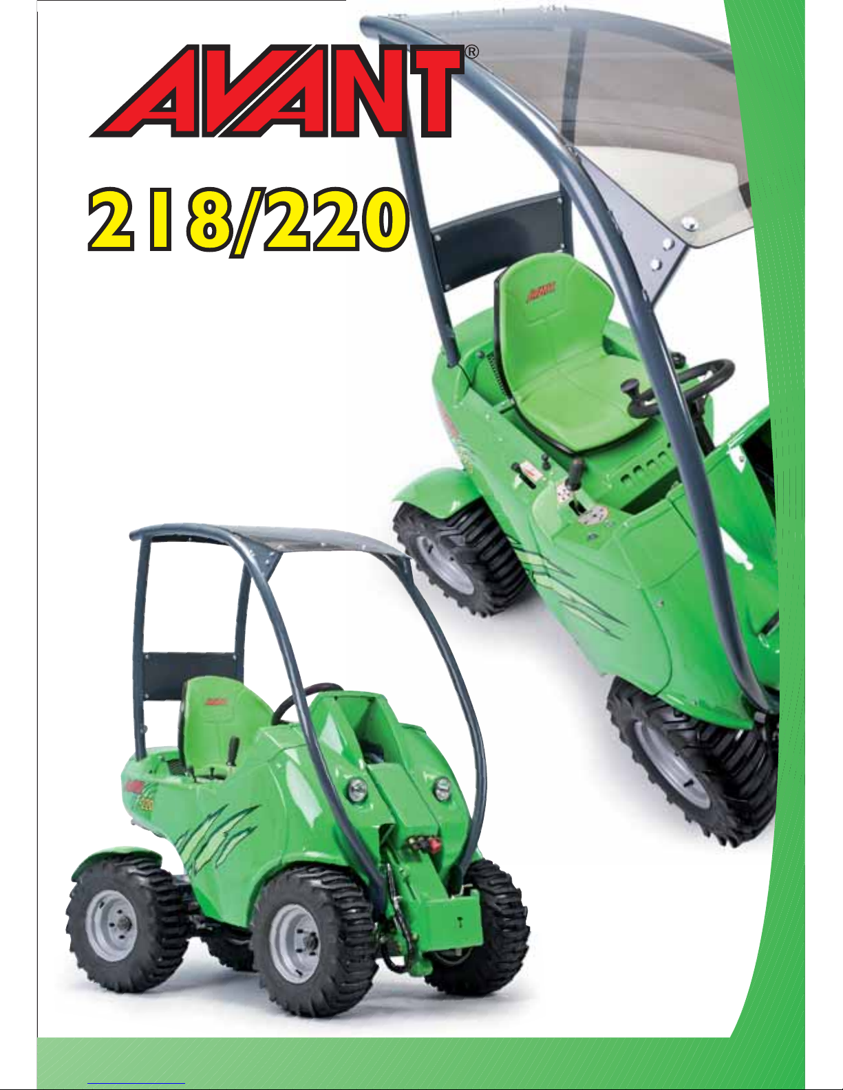
Operators
Manual
2013-
English
Page 2

Table of contents
2
TABLE OF CONTENTS
INTRODUCTION ...............................................................................................................3
AVANT 200 SERIES WARRANTY .....................................................................................3
EC DECLARATION OF CONFORMITY ............................................................................4
HOW TO WORK SAFELY ................................................................................................. 5
DECAL LOCATIONS ..........................................................................................................6
MAIN PARTS OF THE LOADER ........................................................................................7
TECHNICAL SPECIFICATION ..........................................................................................8
LOAD DIAGRAM ................................................................................................................9
CONTROLS ......................................................................................................................10
LOCATION OF BATTERY DISCONNECT SWITCH ......................................................12
STARTING THE ENGINE.................................................................................................12
STOPPING THE ENGINE ................................................................................................12
DRIVE CONTROL.............................................................................................................13
FUNCTION OF DRIVE PEDALS......................................................................................13
STEERING OF THE MACHINE........................................................................................14
LOADER CONTROL.........................................................................................................14
USING THE AUXILIARY HYDRAULICS.........................................................................14
HAND THROTTLE ...........................................................................................................14
COUPLING THE ATTACHMENTS..................................................................................15
MAINTENANCE SCHEDULE ..........................................................................................16
MOUNTING OF THE SERVICE SUPPORT.....................................................................16
SAFETY INSTRUCTIONS FOR MAINTENANCE ..........................................................17
SAFETY INSTRUCTIONS WHEN HANDLING THE BATTERY ....................................17
TRANSPORTING AND LIFTING ....................................................................................17
MAINTENANCE INSTRUCTIONS..................................................................................18
FILTER LOCATION...........................................................................................................20
GREASING POINTS.........................................................................................................20
REFUELING.......................................................................................................................21
DRIVE BELT ......................................................................................................................21
HYDRAULIC SYSTEM......................................................................................................22
ELECTRICAL HARNESS...................................................................................................22
TROUBLESHOOTING .....................................................................................................23
SERVICES MADE..............................................................................................................23
200 Series
Page 3

Introduction, warranty
3
200 Series
INTRODUCTION
AVA NT Tecno Oy wants to thank you for purchasing this AVANT loader. It is the result of Avants
long experience in design and manufacturing of compact loaders.
We ask you that you read and understand the contents of this manual completely before operating
the loader. This will improve your operating and maintenance efficiency, help avoid breakdowns
and damage and extend your machines life.
Contact your local AVA NT dealer for advice regarding service, parts and any
problems relating to the operation of your AVA NT.
AVANT 200 SERIES WARRANTY
This warranty specifically applies to the AVA NT 200 series loaders only and not to any attachments used with
this product.
Any repairs or modifications performed without the prior authorisation of AVA NT Tecno Oy will cancel this
warranty.
During the first year of operation or first 500 hours (whichever is the soonest) AVA NT Tecno Oy warrants
to replace any part or repair any defect which may occur, subject to the terms detailed below:
1) The product has received regular maintenance in accordance with schedules given by the manufacturer.
2) Any damage caused by operation in a negligent manner or exceeding the approved specifications detailed
in this manual is excluded.
3) AVA NT Tecno Oy accepts no responsibility for interruption to working or any other consequential losses
resulting from any failure of the product.
4) Only AVA NT Tecno Oy approved replacement or original quality parts shall be used during routine
maintenance.
5) Any damage caused by the use of incorrect fuel, lubricants, cooling liquid or cleaning solvents is excluded.
6) The Avant Warranty excludes any consumable parts (e.g. tyres, spark plugs, batteries, filters, belts etc.)
except where it can be clearly shown that these parts were defective on original supply.
7) Any damage caused resulting from the use of attachments not approved for use with this product is excluded.
8) In the event a fault occurs which is attributable to manufacturing or assembly defect you should arrange
to return your AVA NT to your authorised dealer for repair. Travel and freight cost are excluded.
Engine warranty: Engines are warranted by the engine manufacturer (Kohler). Warranty conditions for the
engine can be found in the warranty note for Kohler engines and in the Operating Manual for Kohler engines,
delivered with the loader.
IDENTIFICATION OF THE LOADER
Write down the following information about your loader, it will help you when ordering parts etc.
1. Model: AVA NT_____________________Purchase date:______________________________
2. Serial number:________________________________________________________________
3. Engine serial number:__________________________________________________________
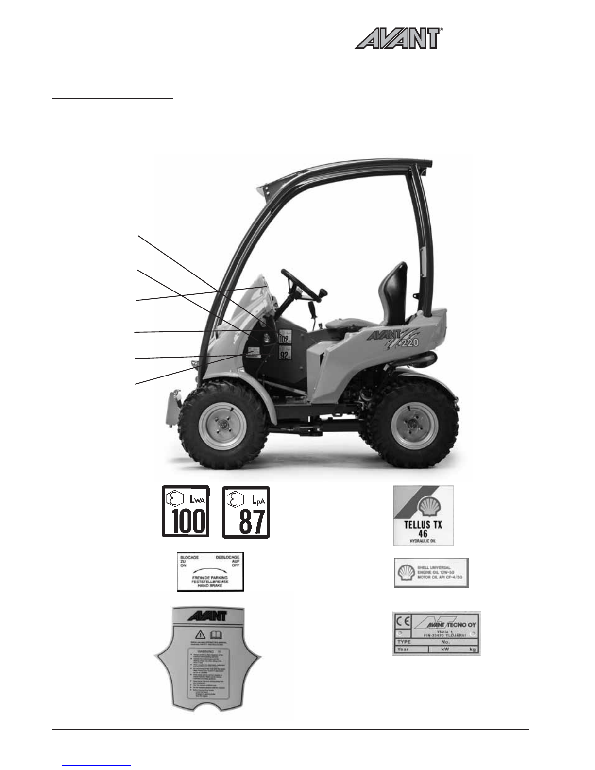
The serial number and model of the loader are printed on the manufacturers plate (decal no. 6,
see page 6). Location of engine serial number can be found in the operating manual of the engine.
Page 4
EC declaration of conformity
4
200 Series
EC DECLARATION OF CONFORMITY
1. Manufacturer: Avant Tecno Oy
2. Address: Ylötie 1
FI-33470 YLÖJÄRVI
FINLAND
3. Technical Construction File Location: Same as Manufacturer
4. We hereby declare that the machines listed below conform to EC Directives:
2006/42/EC (Machinery), 2004/108//EEC (EMC) and 2000/14/EC (Noise Emission).
5. Category: EARTH-MOVING MACHINERY/LOADERS/COMPACT
6. Model: AVANT
7. Serial Number:
8. Year of Manufacture:
9. Directive / Conformity Assessment Procedure / Notified Body:
2006/42/EC Self-certification ---------2004/108//EEC Self-certification ---------2000/14/EC Type-test MTT Agricultural Engineering
Research (VAKOLA)
Vakolantie 55, 03400 Vihti, FINLAND
10. Name: Risto Käkelä
11. Position/Title: Managing Director
12. (Signature) ___________________________
13. Place: Ylöjärvi, Finland
14. Date:
Page 5
200 Series
How to work safely
5
HOW TO WORK SAFELY
An incorrect or careless operation of the loader may
be the origin of a serious accident. Before putting the
machine into operation, familiarise yourself with the
use of the machine and read and understand this
Operators Manual as well as the safety instructions.
THIS SYMBOL INDICATES
THE IMPORTANT
SAFETY FACTORS.
Understand the limitations of speed, braking, steering
and stability as well as loading capacity of the machine
before starting operation. Make sure that every one
who operates or works with this equipment is familiar
with these safety precautions.
The loader must only be used for the tasks and with
the attachments approved by the manufacturer.
If you have no previous experience of the machine,
make sure to do all testing at a safe and open place
with no persons in the area of operation.
SAFETY INSTRUCTIONS
Never use the loader without instructions. Read loader
signs (decals), and this manual.
Start the operation slowly and carefully.
Do not wear loose clothing, long uncovered hair or
jewelry near machine.
When driving be comfortably seated in the driver´s
seat, keep your feet in their proper place in the footwell
and at least one hand on the steering wheel.
Operate the control levers and the lever of auxiliary
hydraulics only when sitting in the driver´s seat.
Operate the control levers with ease and without
hesitation.
When coupling the attachment, make sure that the
locking pin locks in positively.
Never put any part of the body or let anyone go under
the lifted boom.
Do not transport persons in the bucket. The machine
is not designed to lift or to transport persons.
Keep hands, feet and clothing away from any moving
part and/or hydraulic cylinder.
Never carry passengers. Keep other bystanders away
from the work area.
Drive slowly on uneven terrains. Watch out for ditches,
manholes and steep gradients.
Do not drive on too steep a gradient. Load, unload, and
turn on flat level ground.
Make sure that the ventilation is sufficient when working
indoors or otherwise confined area.
Do not use loader in an atmosphere with explosive dust
or gases or where exhaust can contact flammable
material, explosion or fire can result.
Do not transport the load with the boom lifted.
Always carry bucket or attachment as low as possible,
and put the load down whenever you leave the machine.
When lifting or lowering the load, do not operate the
boom control lever abruptly. Turn the lever smoothly
and with care.
Do not exceed rated operating capacity - follow the
load diagrams.
Do not park the machine on a surface with a gradient.
Should this be necessary, use the parking brake and
preferably turn the machine sideways and put down
the bucket. If needed, use chocks behind the wheels.
Before leaving driver´s seat:
- Lower the loader boom
- Place attachment flat on ground
- Stop the engine, remove the key
- Engage the parking brake
Never perform any maintenance or repair operation
when the engine is running.
Stop and cool the engine before adding fuel.
Keep the engine area clean of flammable materials.
Wear eye protection when servicing, and hard hat or
other protective equipment as needed.
When connecting a booster battery for "jump" start,
always make last connection (negative cable) to engine,
never at battery. When removing the "jump" start cable,
always remove the negative cable (-) from engine first.
Never charge a frozen battery.
Lead acid batteries produce flammable and explosive
gases. Keep arcs, sparks, flames and lighted tobacco
away from battery.
Battery acid causes severe burns. In case of acid contact,
wash immediately with water for several minutes and
get medical attention in case of eye contact.
Use a piece of cardboard to check for hydraulic leaks.
Leaking fluids under pressure can enter the skin and
cause serious injury. Medical attention is required if
hydraulic or other fluids contact skin.
Never modify the loader or add attachments not
approved by AVA NT Tecno Oy.
Do not smoke during refueling or driving.
If the loader is transported e.g. on a trailer, make sure
that the articulation joint is securely locked by fitting
the frame lock (painted red, see p. 17) on the left side.
Ensure it is removed before commencing driving again.
When turning with the loader, keep in mind that the
chassis extends beyond the turning radius of the
wheels (collision risk).
Read this Operator's Manual carefully, especially if you
are unfamiliar with the safe use and operation of the
machine.
Page 6
Decal locations
6
200 Series
l
j
k
m
n
o
DECAL LOCATIONS
If any of these decals has been removed or is unreadable it should be replaced without delay.
l
j
k
m
n
o
Page 7
200 Series
Main parts of the loader
7
l
j
k
m
n
o
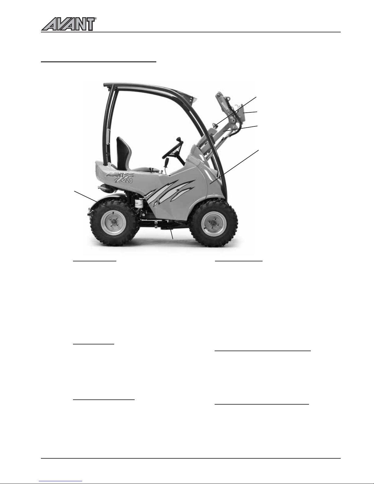
MAIN PARTS OF THE LOADER
Following picture shows the main parts of the loader:
l
j
k
m
n
o
Front frame
Front frame is the part of the loader in
front of the articulation joint. On the
front frame are mounted: drivers seat,
operating controls, engine with
accessories, hydraulic pumps, hydraulic
control valves, hydraulic oil tank, fuel
tank, auxiliary hydraulics outlet, front
wheels, hydraulic motors and the loader
boom with attachment coupling plate.
Back frame
Back frame is the part of the loader
behind the articulation joint. On the
back frame are mounted: rear wheels,
hydraulic motors, counterweights,
trailer coupling.
Articulation joint
Articulation joint connects the front and
back frame. The loader is steered
hydraulically by the steering cylinder
which is mounted between the front
and back frames.
Loader boom
Loader boom is mounted on the front
frame with two pivot pins. The
attachment coupling plate is mounted
on the lower end of the boom. Loader
boom is equipped with a self leveling
system: It keeps the bottom of the
attachment (e.g. bucket, pallet fork)
level when the boom is being lifted or
lowered. Tilt movement can be adjusted
with control lever no. 7 (see page 11).
Attachment coupling plate
Attachments are mounted on the
attachment coupling plate. Attachment
is the equipment with which the work
is being performed (e.g. bucket, pallet
fork, rotary broom etc.).
Auxiliary hydraulics outlet
The hydraulic hoses of hydraulically
operated attachments are mounted on
this outlet with quick couplers. The
outlet is double acting: it has two
pressure lines and one return line.
Page 8
Technical specification
8
200 Series
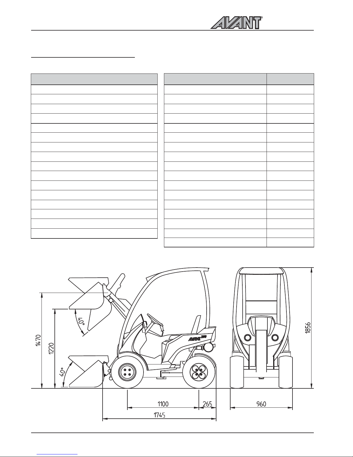
TECHNICAL SPECIFICATION
Model
Length
Width
Height
Ground clearance
Weight
Standard tyres
Drive speed
Drive hydraulics
Hydraulic oil tank capacity
Auxiliary hydraulics
Steering wheel rounds left / right
Turning radius inside / outside
Lifting height
Max. pulling force
Max. lifting capacity (hydr.)
AVANT 218/220
1745 mm
960 mm
1856 mm
170 mm
590/620 kg
20x8.00-10Grass / 21x8.00-10TR
0 - 10 km/h
hydrostatic
23 l
AVANT 216: 23 l/min 185 bar
AVANT 220: 29 l/min 185 bar
1,8 / 2,4
850 / 2100 mm
1470 mm
600 daN
350 kg
Model
Engine type
Function
Cooling system
Number of cylinders
Starter
Bore * stroke
Displacement
Max. output
Fuel
Fuel tank capacity
Engine oil capacity
Engine oil type
Viscosity
Valve clearance, suction
Valve clearance, exhaust
Sound pressure level L
PA
Sound output level L
WA
AVANT 218
Kohler CV620
4 stroke
air
2
electric
77 * 67 mm
624 cm
³
13,4 kW (18 hv)
petrol min. 92 oct.
9 l
2,0 l
API CF-4/SG
SAE 10W-30
0,08 mm
0,09 mm
89 dB (A)
102 dB (A)
AVANT 220
Kohler CV640
4 stroke
air
2
electric
77 * 67 mm
624 cm
³
14,9 kW (20 hp)
petrol min. 92 oct.
9 l
2,0 l
API CF-4/SG
SAE 10W-30
0,08 mm
0,09 mm
89 dB (A)
102 dB (A)
Page 9
LOAD DIAGRAM
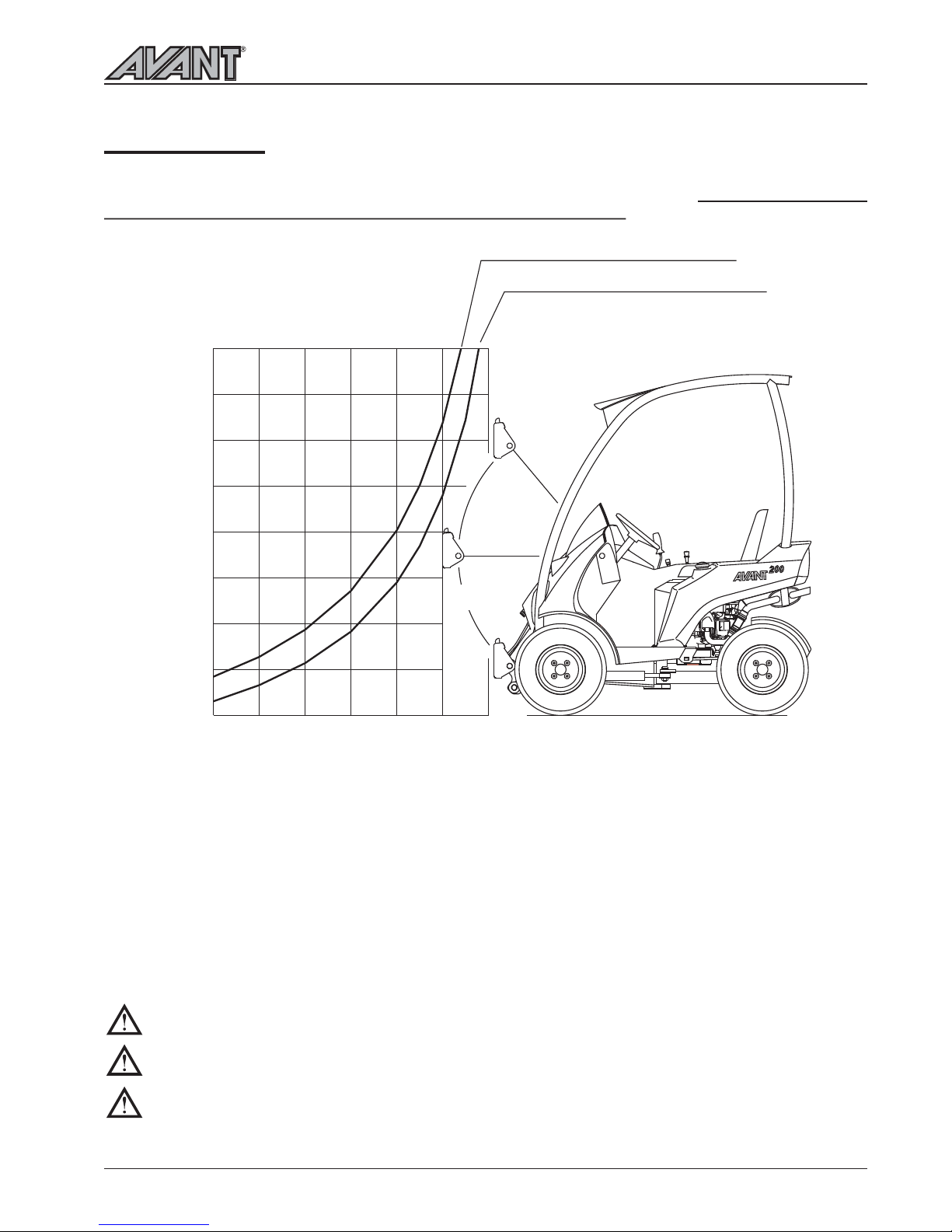
The lifting capacity of the loader is limited by the possibility of tipping around the front axle. The diagram
below shows the tipping loads and max. allowed loads in different loading situations on an even level surface
with the loader in maximum articulation (i.e. minimum restoring moment).
200 Series
Load diagram
9
The diagram can be interpreted as follows:
The diagrams show max. loads with the boom in different positions and with the load at different distances
from the attachment coupling plate
Max. load should be reduced when the load is farther away from the attachment coupling plate
If the center of gravity of the load is 50 cm in front of the attachment coupling plate, max. load is 230 kg
with a driver weighing 80 kg and with a safety factor of 1,5 against tipping over (n=1,5)
With the load carried at low level max. load of 300 kg can be transported at the above mentioned case
Please note that the diagrams are based on the machine operating on a level, even and firm supporting
ground. Loads should be significantly reduced when operating on gradients and/or on soft ground.
ALWAYS KEEP AND TRANSPORT THE LOAD AS CLOSE TO THE GROUND AS POSSIBLE
NEVER TAKE A HEAVY LOAD ON THE LOADER FROM HIGH LEVEL - E.G. FROM TRUCK,
SHELF ETC. - RISK OF TIPPING OVER!
ALWAYS PUT DOWN THE LOAD BEFORE LEAVING THE MACHINE
AVANT 200 series Load diagram
Max. load (n=1.5 80kg driver
Max. load (n=1.5 no driver)
0
0.50m
0.25m
1.00m
1.25m
0.75m
100kg
150kg
200kg
250kg
300kg
350kg
400kg
450kg
500kg
Page 10
Controls
10
200 Series
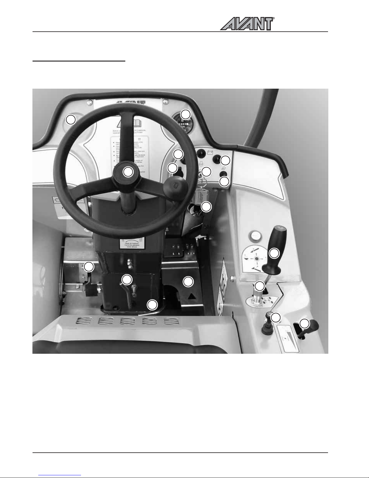
OPERATING CONTROLS
Following picture shows the location of operating controls. The location and function of controls may be
slightly different in different models, see following pages.
1
12
2
3
4
5
6
7
8
9
10
11
13
14
15
16
1. Steering wheel
2. Hour meter
3. Ignition switch
4. Signal horn
5. Light switch
6. Fuse box
7. Control lever of boom and bucket
8. 12 V outlet
9. Hand throttle lever
10. Choke
11. Drive pedal, right: drive forward
12. Drive pedal, left: drive backward
13. Parking brake handle
14. Lockable auxiliary hydraulics control pedal
15. Oil temperature gauge (optional extra)
16. Drive circuit release valve
17. Work light indicator
17
Page 11
200 Series
Controls
11
CONTROL OF LOADER BOOM, ATTACHMENTS AND OTHER FUNCTIONS
Most of the functions of the loader are controlled at the control panel on the right side of the operator:
Boom and bucket movements, engine revs etc.. Following pictures show the different functions:
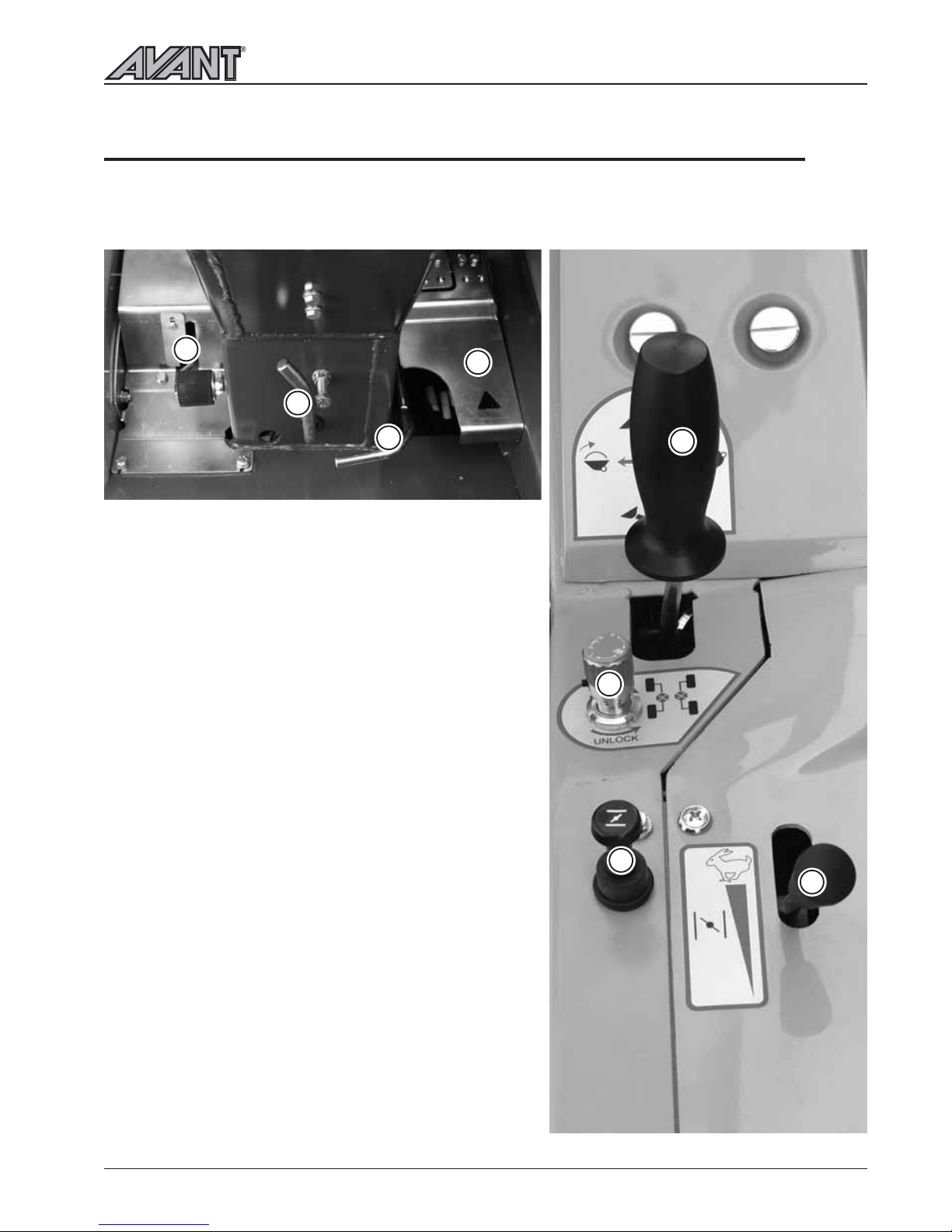
7. Control lever of boom and bucket
Pull backward to lift the boom
Push forward to lower the boom
Push left to raise the tip of the bucket (filling)
Push right to lower the tip of the bucket (emptying)
9. Hand throttle lever
Push forward to increase engine revs
Pull backward to reduce engine revs
10. Choke
Lift up the knob to increase the choke
Push down the knob to reduce choke
11. Drive pedal, right: drive forward
12. Drive pedal, left: drive backward
13. Parking brake handle
locking: turn left and down into locking position
releasing: turn right and up to release parking brake, if
necessary make a sharp turn with the steering wheel
so that the locking pins unlock in the front wheels
14. Control pedal of auxiliary hydraulics
(hydraulically operated attachments)
Lift the pedal carefully to test the operating direction of
the attachment
Press + turn left to locking position: the attachment
operates in reversed direction
17. Drive circuit release valve
In normal operation (unlock selected) hydraulic oil
flows in series from motor to motor. When turning the
knob counterclockwise the hydraulic oil flow is gradually
diverted, and in lock position oil flows parallel between
the hydraulic motors on each side, similar to a parallel
differential lock in operation.
17
14
7
9
12
11
13
10
Page 12
Starting the engine
12
200 Series
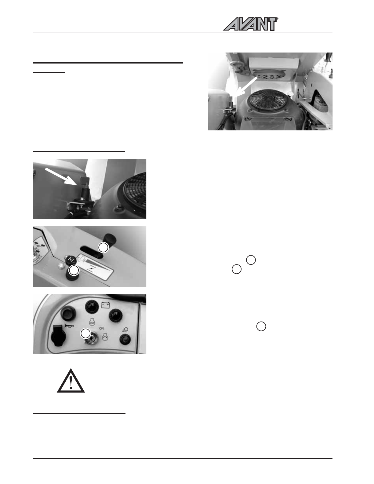
STARTING THE ENGINE
(see also KOHLER Owners Manual)
Turn the battery disconnect switch to ON
Adjust the throttle lever to
¼.
Lift up the choke button
NOTE: Do not use the choke if the engine is warm
or the air temperature is high
Turn the ignition key to the right until engine starts, then
let the key return to ON position
Reduce choke (push choke button down) as soon as
engine has started, push completely down when
engine has warmed up
Turn the ignition key to the OFF position (to the left)
Turn the power off with the battery disconnect switch
STOPPING THE ENGINE
THE ENGINE CANNOT START IF THE AUXILIARY
HYDRAULICS CONTROL PEDAL IS IN LOCKING
POSITION.
LOCATION OF BATTERY DISCONNECT
SWITCH
All AVANT loaders are equipped with a battery disconnect
switch. In AVANT 218/220 the switch is located under the
drivers seat in engine compartment. Following pictures show
the location of this switch.
10
9
10
9
3
3
Page 13
200 Series
Drive control
13
DRIVE CONTROL
FUNCTION OF DRIVE PEDALS
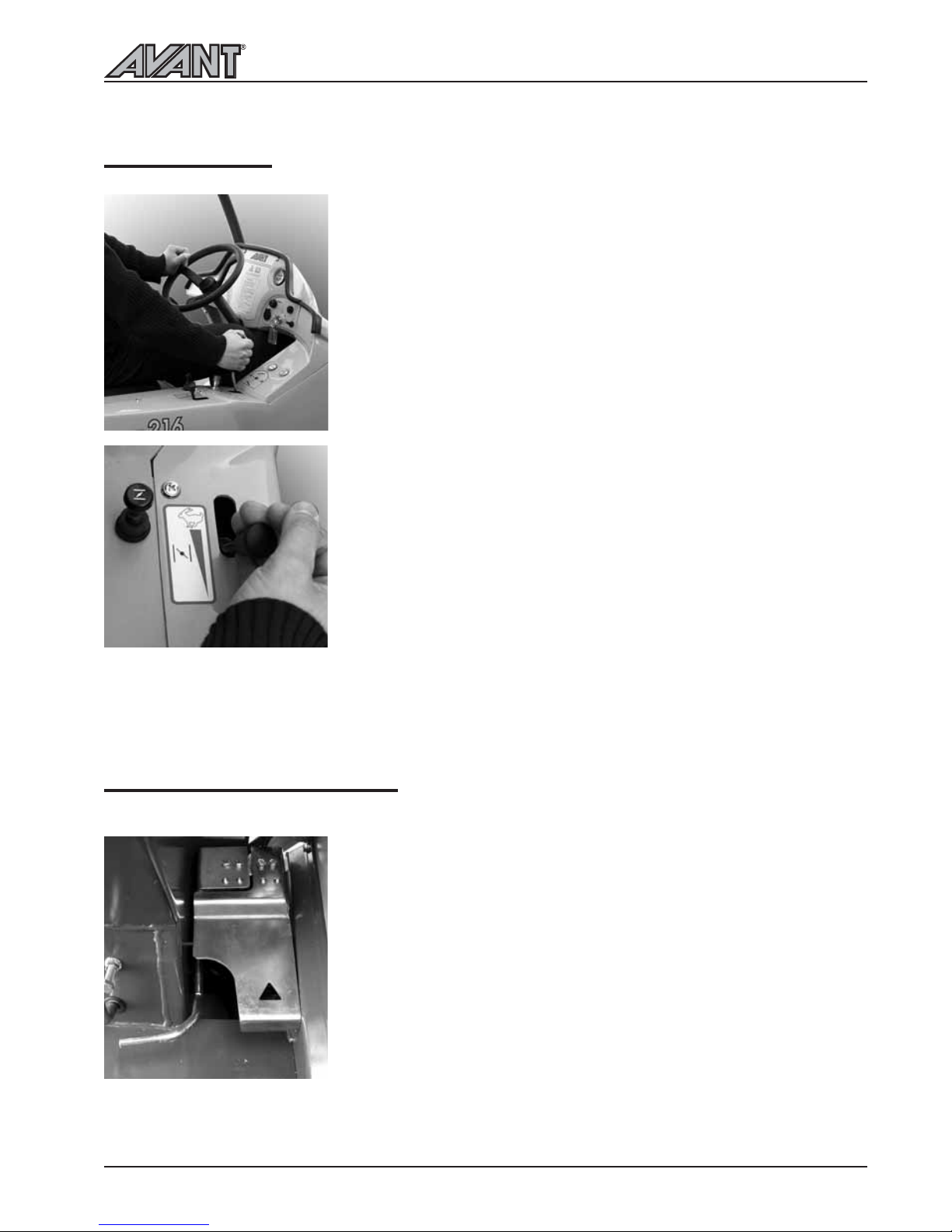
When thinking about the function of the two drive pedals, they should be
compared to gears, not to a conventional throttle pedal. The drive pedal
in a way shifts on a higher gear the more the pedal is pressed. Therefore
you shouldnt press the pedal more when the engine starts to struggle.
Pressing the pedal just causes the engine to stop.
When you want to have a high pulling force:
1. Use high engine revs
2. Select a relatively slow drive speed with the drive pedal. That is: press the
pedal only lightly (= select a low gear). This way the full output of the
hydraulic system and the engine can be taken out.
AVANT 200 series loaders are equipped with a hydrostatic drive system,
there is a variable displacement hydraulic pump in the drive circuit. The oil
flow of this drive pump is steplessly adjusted with the two drive pedals. The
drive pedals act in a proportional way to control the drive speed and power
available at the drive motors.
This hydrostatic drive system has different operating characteristics to a
mechanical drive. To get maximum pushing power push the pedals lightly for higher travel speed push the pedal harder.
Driving of the machine is controlled with the drive pedals as follows:
Select the revs of the engine with the hand throttle lever on the control
panel. The basic rule is: use lower revs for lighter work and higher revs for
hard work.
If you want to drive forward, press gently on the right drive pedal until
the machine starts to move slowly. The desired drive speed is selected with
the drive pedal: the more the pedal is pressed the faster you will travel.
When you wish to stop gently release the pedal by lifting of your foot, and
the machine will slow and stop.
Drive backward is controlled with the left drive pedal in the same way as
drive forward: the more the pedal is pressed the faster you will travel.
When you have learned how to drive on low speed, increase speed gradually
and learn how to drive with higher drive speeds.
Page 14
Steering of the machine
14
NOTICE! THE ENGINE CANNOT
START IF THE AUXILIARY
HYDRAULICS CONTROL PEDAL IS
IN THE LOCKING POSITION.
THE OPERATING DIRECTION OF
THE ATTACHMENT DEPENDS ON
THE COUPLING OF THE
ATTACHMENT HOSES. MAKE SURE
THAT THERE ARE NO PERSONS IN
THE DANGER AREA WHEN
TESTING THE OPERATING
DIRECTIONS. CHANGE THE
COUPLING OF THE HOSES IF
NECESSARY.
STEERING OF THE MACHINE
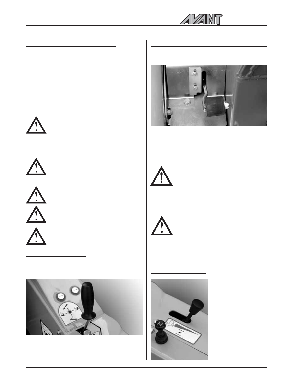
Steering of the machine is actuated via the steering
wheel. The steering wheel is hydraulically powered.
A practical way of steering is to steer with your left
hand on the knob of the steering wheel. This way
your right hand is free to operate other functions.
Familiarise yourself with the special drive features and
space needs of this articulated loader on a flat, even
and open place. Remember that, when turning, the
front frame of the loader extends beyond the turning
radius of the wheels.
LOADER CONTROL
The loader boom and bucket are controlled with the
multi-function lever sideways (tilt) and back & forward
(boom up & down).
· Pull backward to lift the boom
· Push forward to lower the boom
· Push left to raise the tip of the bucket (filling)
· Push right to lower the tip of the bucket (emptying)
USING THE AUXILIARY HYDRAULICS
Auxiliary hydraulics (hydraulically operated attachments)
are controlled with the pedal no. 14 in the footwell.
Auxiliary hydraulics control pedal locks in the locking
position (down left) which facilitates operation of the
attachments that require constant oil flow (rotary
broom, backhoe etc.).
HAND THROTTLE
When driving, the
revolution speed of the
engine can be adjusted
with the hand throttle
lever, if necessary. Do
not turn the machine
with a high driving travel
speed.
NEVER TIP OVER THE LOADER.
NEVER USE A HIGH DRIVE SPEED
WHEN TURNING.
In particular: when the loader boom is up
the stability of the machine is much weaker
when turning.
WHEN DRIVING, ALWAYS KEEP
THE LOADER BOOM AS LOW AS
POSSIBLE. Risk of tipping over increases
considerably when there is a heavy load
on the loader (a heavy attachment or a
big load in the bucket) and the boom is
up when driving.
ALWAYS REMEMBER SAFETY
FIRST.
TEST ALL THE FUNCTIONS OF THE
LOADER AT AN OPEN AND SAFE
PLACE.
MAKE SURE THAT THERE ARE NO
PERSONS IN THE OPERATING
AREA OF THE MACHINE.
200 Series
Page 15
15
Coupling the attachments
200 Series
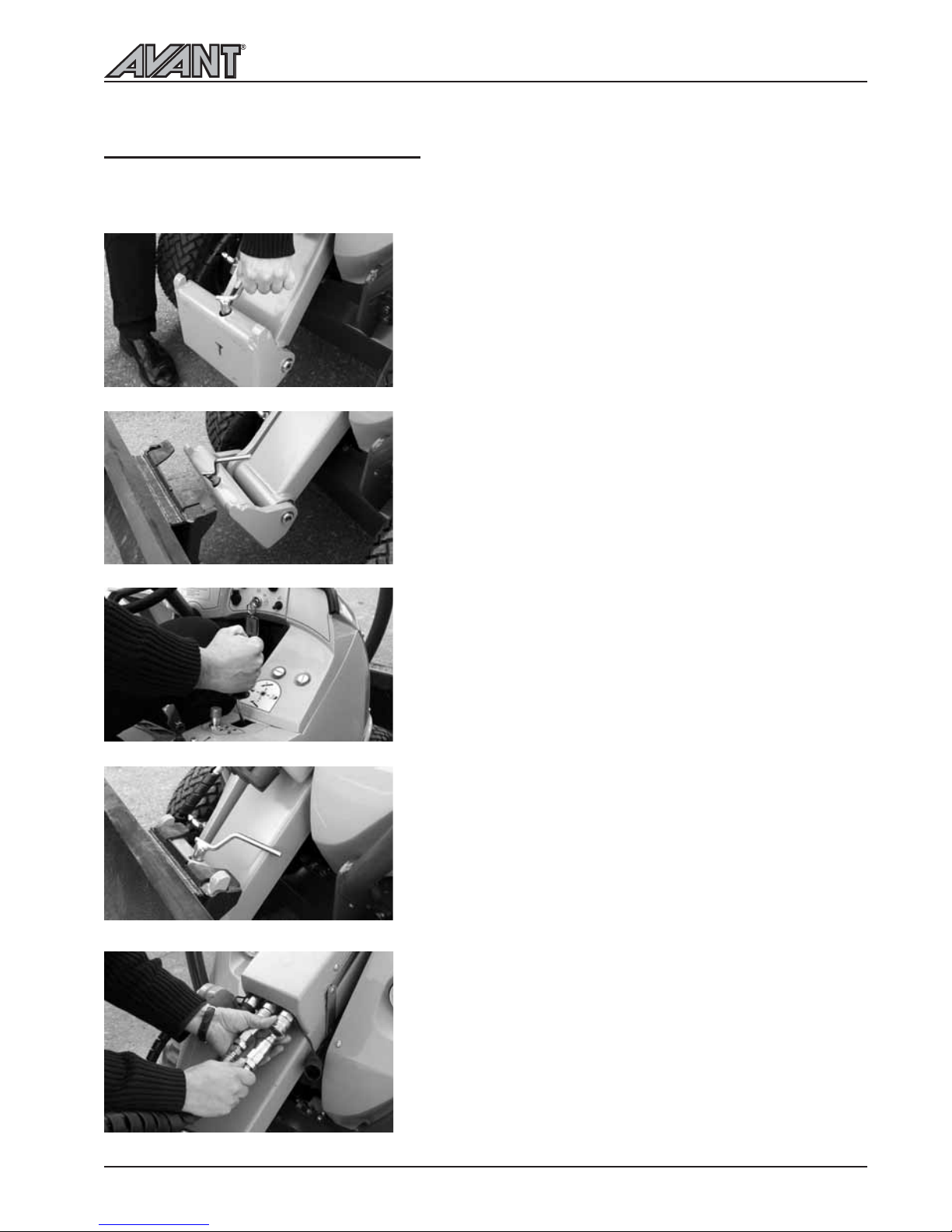
COUPLING THE ATTACHMENTS
Coupling of the attachments into the attachment coupling plate happens as follows:
Stage 1:
Lift up the locking pin and turn it backward so that it remains
in the locked up position.
Make sure that the pin remains in the up position, otherwise
you cannot couple the attachment properly!
Stage 2:
Turn the attachment coupling plate with the tilt movement
so that the upper edge of the plate leans forward.
Drive the loader into the attachment so that the pins in the
upper left and right corner of the attachment coupling plate
go into the holes of the attachment bracket.
Stage 3:
Lift the boom a little so that the attachment lifts off of the
ground.
Pull the boom control lever to the left so that the lower edge
of the attachment coupling plate turns into the attachment.
Stage 4:
Pull the boom control lever more to the left so that attachment
coupling plate turns more and the boom pushes the pin
down in the hole of the attachment.
CAUTION! Make sure that the pin locks properly
down in the hole of the attachment.
Stage 5:
If the attachment is equipped with hydraulic hoses, make
sure to connect the hoses in the quick couplings on the loader.
Engine must be stopped when connecting the hoses. Before
connecting the hoses move the auxiliary hydraulics control
lever in both directions a couple of times in order to release
eventual back pressure.
Additional information about the coupling is provided in the
instruction manual of the attachment.
NOTICE! When fitting an attachment, make sure that
the hydraulic hoses are not overstretched and are not
in a position where they can be trapped during the
operation of the machine and attachment.
Page 16
Maintenance schedule
16
MAINTENANCE SCHEDULE
Following table shows the maintenance and service points and intervals. There are more detailed instructions
about each service operation, in numerical order, on the following pages.
200 Series
LOADER
1. Clean the machine
2. Check tyre pressure
3. Check battery electrolyte level
4. Check hydraulic oil level
5. Change hydraulic oil filters
6. Change hydraulic oil
7. Check tightness of bolts, nuts
and hydraulic fittings
8. Check pressure of hydraulic system
9. Adjust pressure of hydraulic system
10. Grease the machine
ENGINE*)
11. Check engine oil level
12. Change engine oil
13. Clean air filter
14. Clean fuel filter and
sediment cup
15. Clean spark arrester
16. Change spark plug
17. Change engine oil filter
18. Change air cleaner element
19. Check and adjust valve clearances
Every
week
Every
year
Every
1000 h
Every
800 h
Every
500 h
Every
400 h
Every
200 h
Every
100 h
After
50 h
After
25 h
Every
day
l
l
l
ll
ll
l
l
l
l
l
l
l
l
l
l
l
n
n
n
n
n
n
l
Maintenance operation
n When necessary
*) More specific engine maintenance instructions can be found in the owners manual of the engine,
supplied with the loader.
l
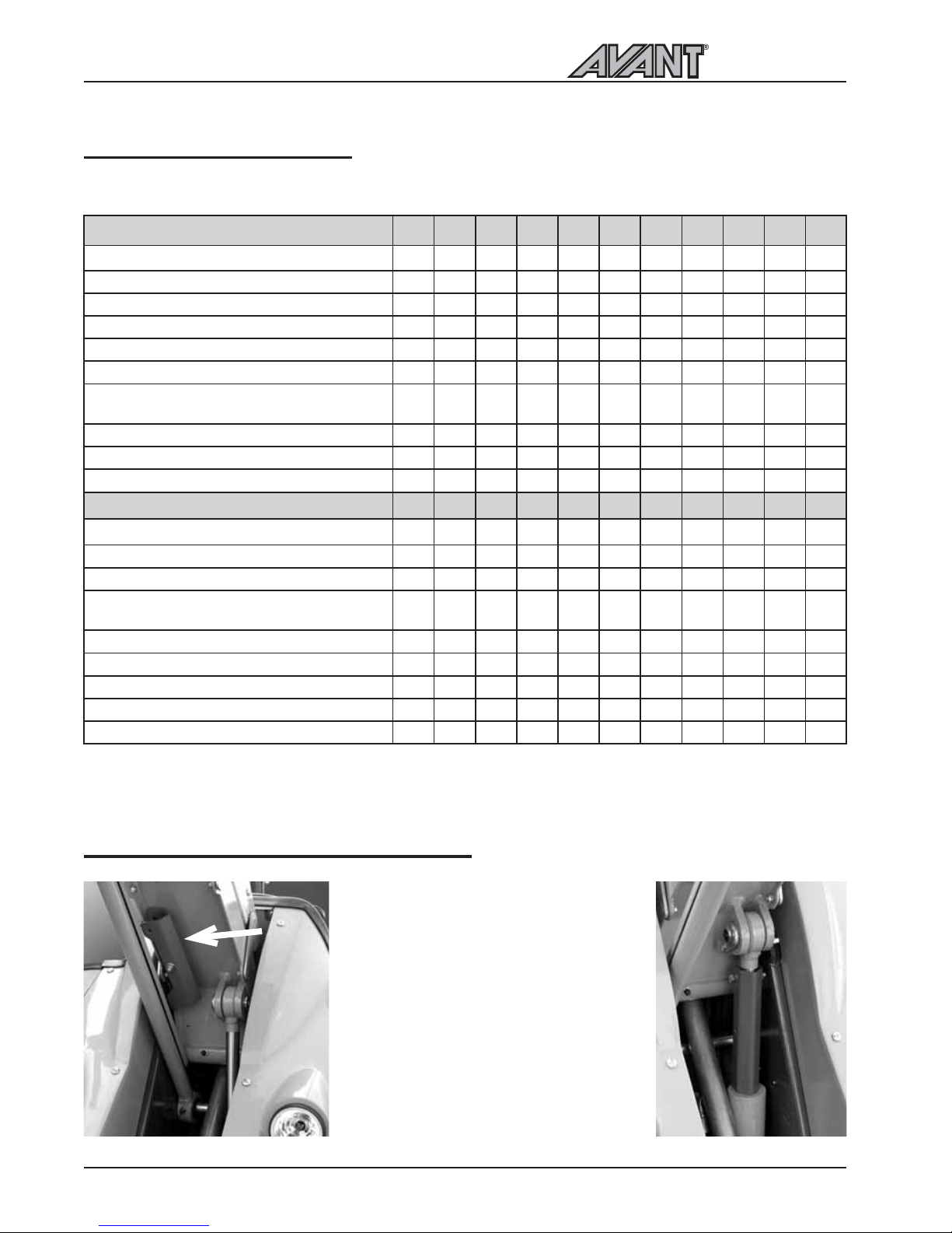
Always secure the lifting boom with the
service support whenever working
under it. Make sure that the boom stays
up by putting the service support on
the lift cylinder piston rod.
The red service support is located under
the boom and fastened with a bolt
Make sure to secure the service support
by locking it on the piston rod by the
bolt
MOUNTING OF THE SERVICE SUPPORT
Page 17
17
Safety instructions for maintenance
200 Series
SAFETY INSTRUCTIONS FOR MAINTENANCE
ALWAYS REMEMBER SAFETY DURING MAINTENANCE
DO NOT PERFORM ANY SERVICE OPERATION WHEN THE ENGINE
IS RUNNING
USE THE SERVICE SUPPORT ON THE BOOM CYLINDER
DO NOT GO UNDER UNSUPPORTED BOOM
DO NOT SMOKE DURING SERVICE OPERATIONS
BEWARE POSSIBLE HIGH PRESSURE IN HYDRAULIC CIRCUITS
SAFETY INSTRUCTIONS WHEN HANDLING THE BATTERY
- BATTERY CONTAINS CORROSIVE SULFURIC ACID.
- AVOID CONTACT WITH SKIN OR CLOTHES. IF ELECTROLYTE GETS
ON YOUR SKIN OR CLOTHES, FLUSH WITH A LOT OF WATER.
- IN CASE OF CONTACT WITH EYES, FLUSH WITH A LOT OF WATER
FOR AT LEAST 15 MINUTES AND CALL A DOCTOR IMMEDIATELY.
- WHEN CHARGING THE BATTERY GIVES OFF POTENTIALLY EXPLOSIVE
GASES DO NOT SMOKE WHEN HANDLING THE BATTERY.
- IN ORDER TO AVOID SPARK EMISSIONS ALWAYS DISCONNECT THE
NEGATIVE (-) CABLE FIRST AND CONNECT IT LAST.
- BEFORE CONNECTING THE BATTERY CABLES MAKE SURE THAT THE
POLARITY IS CORRECT: FAULTY CONNECTION WILL SERIOUSLY
DAMAGE THE ELECTRIC SYSTEM OF THE ENGINE.
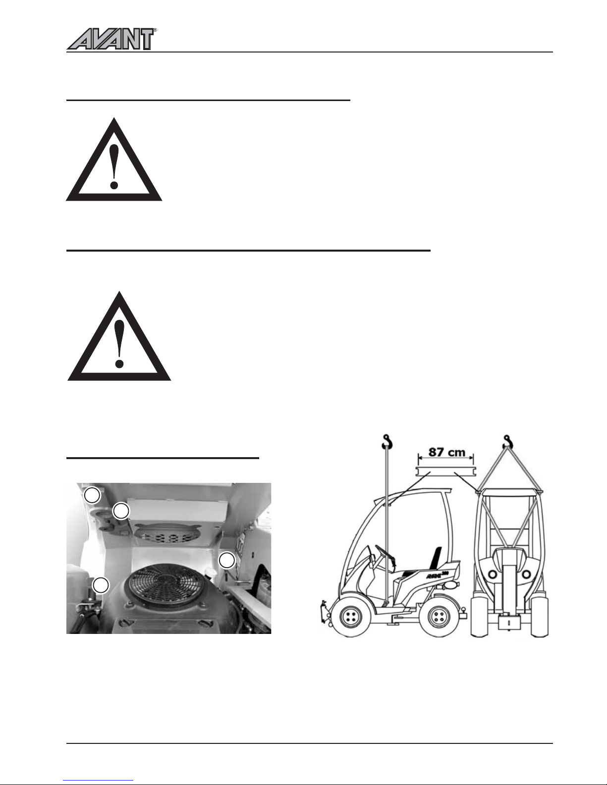
TRANSPORTING AND LIFTING
Following safety devices are located under the
operator seat:
1. Frame lock:The frame of the loader can be
locked with the red frame lock.
2. Seat locking rod: Keeps the seat in upright
position when working in the engine
compartment.
1
2
3
4
3. Lifting hook: Must be installed in the floor plate
when lifting the loader. Lifting sling must be conducted
through the steering wheel. Attach a slotted bar under
the canopy, which supports the sling at a distance at
least 87 cm wide (make sure the sling is strong enough).
This protects the canopy from damaging.
4. Battery disconnect switch: Switches off the
power supply from battery.
Page 18
Maintenance instructions
18
200 Series
1. CLEANING OF THE LOADER
Cleanliness of the loader is not only a question of
outer appearance. All surfaces, painted and others,
will stay in better condition when they are cleaned
regularly. A clean machine also lasts longer. A dirty
machine will run hotter and will collect dirt into the
air cleaner, which is likely to damage the engine. Pay
special attention to the cleanliness of the engine, the
oil tank cover, the engine compartment and the
hydraulic pump compartment. The loader can be
washed with a pressure washer.
ATTENTION! the loader is equipped with a hydraulic
oil cooler, which is located behind the drivers seat,
make sure to clean the oil cooler cell with compressed
air every time you are servicing the loader - and even
more frequently if the loader is being used in dusty
conditions.
2. TYRE PRESSURE
Correct tyre pressure means that the tyres last much
longer. Wrong tyre pressure increases tyre wear and
can be a safety risk when working with the loader.
Recommended tyre pressure is 2.3 bar (33.4 PSI).
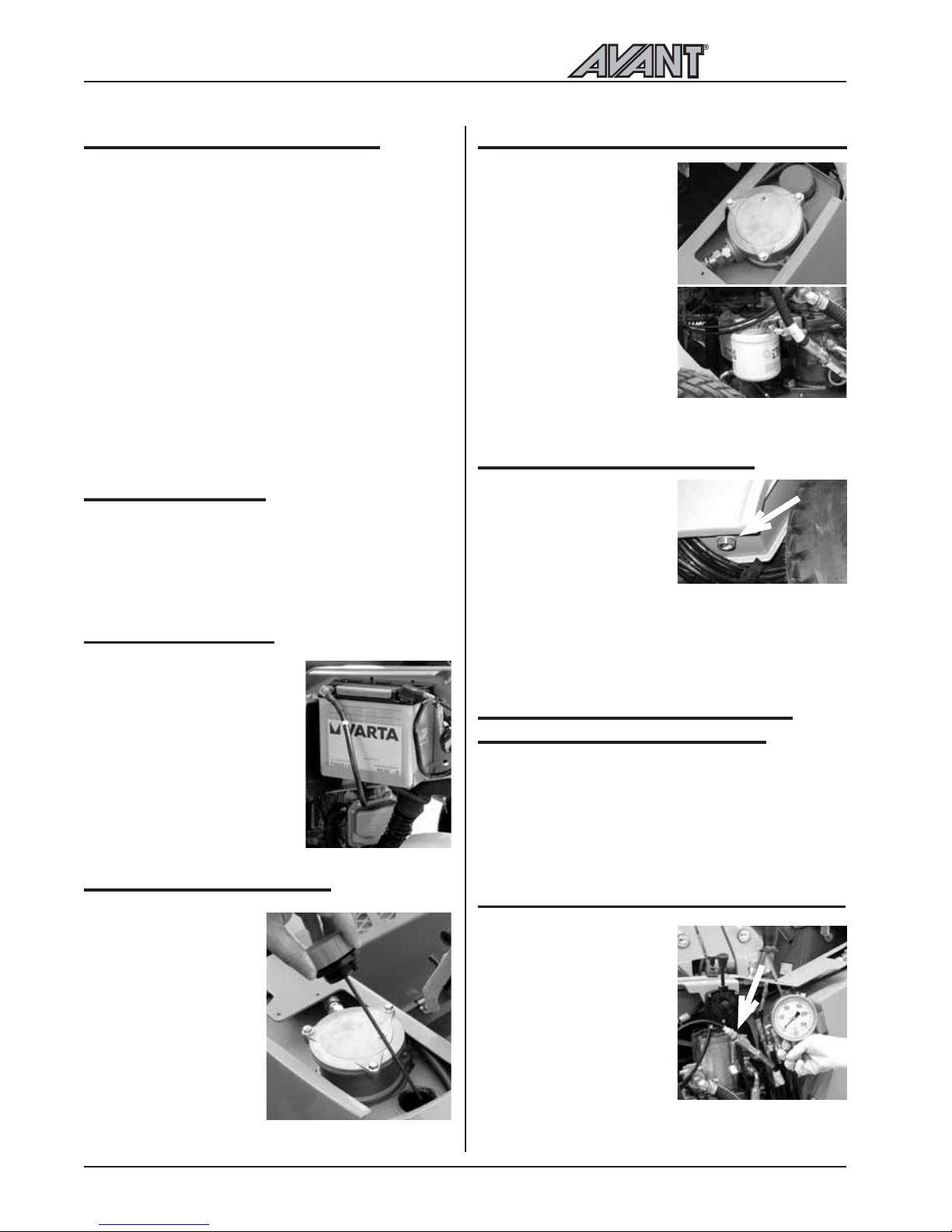
3. BATTERY CHECK
In order to secure the starting
and safe operation the battery
of the loader must be checked
regularly. Checking the
electrolyte level of the battery
happens by opening the filler
caps. ATTENTION! Clean the
battery before opening the caps
so that dirt cannot get in the
battery. Check also the contacts
and clean if necessary.
4. HYDRAULIC OIL LEVEL
Hydraulic oil level can be
checked with the dipstick
in the filler. Oil level
should be between the
two marks in the dipstick.
Refill when necessary.
Clean the area before
checking hydraulic oil
level. Do not let any
contaminents enter the
hydraulic tank during this
procedure.
5. CHANGING OF HYDRAULIC OIL FILTERS
The hydraulic oil return filter
is located on top of the
hydraulic oil tank, under the
right cover beside steering
wheel. Take off the cover
and replace the oil filter
cartridge.
The hydraulic pressure filter
is located under the right
side cover beside the
hydraulic pumps. When
unscrewing the filter hold
the screw in the housing
with a 12 mm allen key and
replace the filter.
6. HYDRAULIC OIL CHANGE
When changing hydraulic oil,
the oil can be removed with
a suction pump or by opening the drain plug on the
right side of the front frame,
behind the front wheel. In
both cases it is important to clean the magnetic drain
plug. Hydraulic oil tank capa-city is 23 litres. Use ISO
VG-46 certified mineral hydraulic oil (e.g. Shell Tellus
TX oil). Use of synthetic hydraulic fluids is not
permitted.
7. CHECK AND TIGHTENING OF
BOLTS, NUTS AND FITTINGS
Check tightness of bolts, nuts and hydraulic fittings
regularly. ATTENTION! Tighten wheel nuts after
first 5 operating hours. Check tightness of wheel
nuts regularly. Wheel nuts shall first be tightened
to 100 Nm diagonally opposite and finally
tightened to 120 Nm.
8.
CHECK PRESSURE OF HYDRAULIC SYSTEM
Pressure checking points for
different functions are as
follows:
Boom movement:
Pressure is checked from
the manometer fitting,
which is located under the
right side cover, beside the
main hydraulic valve.
Pressure is measured with
full engine revs and loading
the hydraulics in the movement end position of boom
or attachment plate. The presure setting is 185 bar.
Page 19
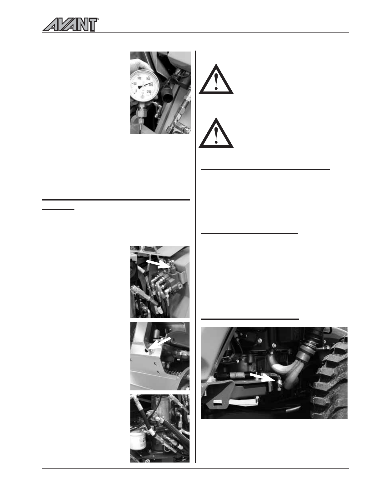
Auxiliary hydraulics: Pressure
is checked by mounting the
manometer in the female
auxiliary hydraulics quick
coupling, with full revs and by
turning the aux. hydraulics
control lever. The presure
setting is 185 bar.
Drive pressure: Can not be
measured. If the pressures are
clearly wrong one must change
the pressure relief cartridges
which have fixed pressure
setting.
It is recommended pressures should only be checked
by a competent and experienced technician
. Call
your AVANT dealer if you need assistance.
9. ADJUST PRESSURE OF HYDRAULIC
SYSTEM
If the pressure of hydraulic system does not seem to
be correct or pressure check indicates that the pressure
is wrong, it can be adjusted. Following pictures show
the pressure adjusting points.
Boom movements: Pressure
is adjusted from the pressure
relief valve at the main control
valve. Pressure relief valve is
the first section of the control
valve, in front of the first valve
segment. Adjust by turning the
hexagonal head screw.
Auxiliary hydraulics: Pressure
is adjusted from the pressure
relief valve behind the left front
wheel. Adjust by turning the
hexagonal head screw.
Drive hydraulics: Can not be
adjusted. If the pressures are
clearly wrong one must change
the pressure relief cartridges
which have fixed pressure
setting.
10. GREASING OF THE MACHINE
Greasing of pivot points is very important in order to
avoid wear. Most of the greasing points are on the
loader boom. There are altogether 10 grease nipples
on the loader. The pictures on page 20 shows the
location of grease nipples.
11.-19. SERVICE, ENGINE
AVANT 218 is equipped with the Kohler CV620
petrol engine. Service and maintenance instructions
for this engine can be found in the Kohler Operators
Manual supplied with the loader.
AVANT 220 is equipped with the Kohler CV640
petrol engine. Service and maintenance instructions
for this engine can be found in the Kohler Operators
Manual supplied with the loader.
12. ENGINE OIL CHANGE
When changing the engine oil. Use the Oil line pictured
above to drain out the old oil.
Maintenance instructions
19
200 Series
WARRANTY DOES NOT
COVER DAMAGES CAUSED
BY EXCESSIVE HYDRAULIC
PRESSURE.
NEVER EXCEED THE RECOMMENDED HYDRAULIC PRESSURE SETTINGS. EXCESSIVE
HYDRAULIC PRESSURE WILL
DAMAGE THE HYDRAULIC
PUMPS, CYLINDERS, AND
HYDRAULIC MOTORS.
Page 20
Filters, greasing points
20
200 Series
FILTERS
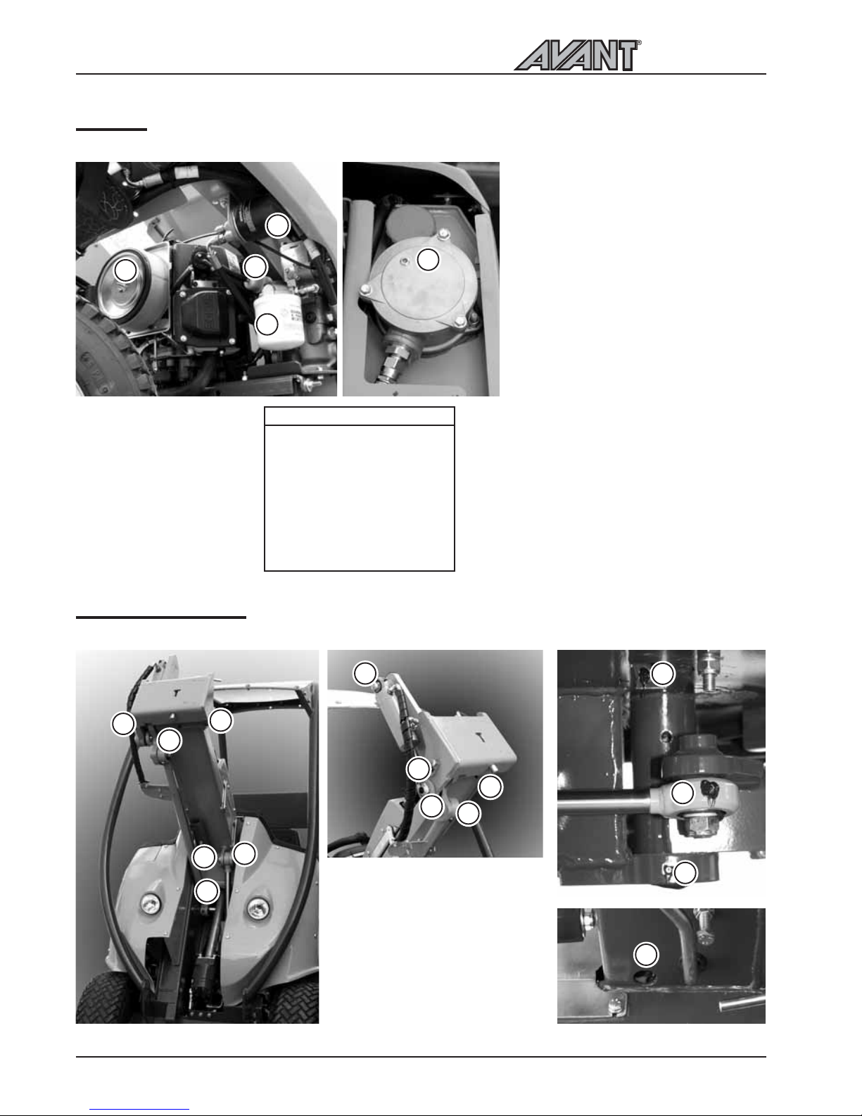
Following pictures and tables show the location and part numbers for the filters.
5
1
6
2
3
GREASING POINTS
Following pictures show the location of greasing points.
1. Lift cylinder, both ends
2. Self leveling bar, both ends
3. Pivot pins on loader boom
4. Tilt cylinder, both ends
5. Shot bolts and joint in
attachment coupling plate
6. Articulation joint
7. Steering cylinder
1. Hydraulic oil filter,
pressure
2. Fuel filter
3. Air filter, element
4. Air filter, outer
5. Hydraulic oil filter, return
6. Engine oil filter
A46683 218/220 Filter kit
AVANT 218/220
64825 Air filter, element
64826 Air filter, outer
74093
Hydr. oil filter, return
64807 Hydraulic oil filter,
pressure
64827 Fuel filter
64824 Oil filter
A3958 Breather hydr. dipstick
64828 Spark plug
1
2
2
3
2
4
5
5
6
6
1
7
4
5
5
Page 21
Refueling
21
200 Series
DO NOT SPILL FUEL WHEN
REFUELING. SHOULD THIS
HAPPEN, WIPE THE FUEL AWAY
IMMEDIATELY IN ORDER TO
AVOID RISK OF FIRE.
ALWAYS STOP THE ENGINE
BEFORE REFUELING.
KEEP THE ENGINE AWAY FROM
OPEN FIRE.
REFUELING
Check fuel level and fill the tank if necessary. Never
use petrol mixed with oil or unclean petrol. Do not
let dirt, dust or water get in the fuel tank. Make sure
that the filler cap is properly tightened after refueling.
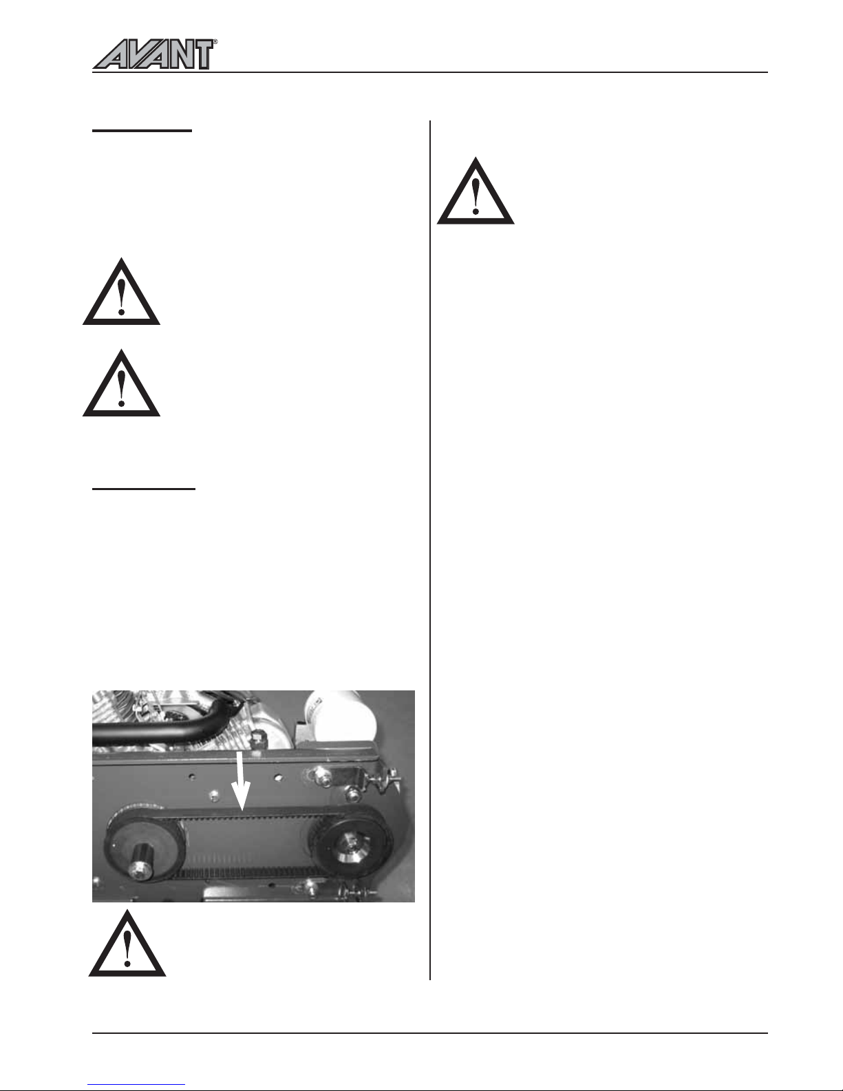
DRIVE BELT
AVANT 218/220 is equipped with a drive belt which
connects the hydraulic pump to the engine. The belt
may get loose over a long period of time and may
need tightening.
There is a hole in the bottom of the loader for checking
the tightness of the drive belt. Belt is correctly tightened
when it moves in the middle of the belt 9 mm when
70 N force is applied (look at the picture).
Belt tightening device increases tension of the drive
belt (pulls the pump away from the engine) when the
two screws on the right are being tightened. Loosening
of these screws reduces tension of the drive belt.
IF THE BELT IS TOO TIGHT IT
GIVES A WHISTLING NOISE. IN
THIS CASE LOOSEN THE BELT
AND CHECK AND ADJUST THE
TIGHTNESS. LOOSEN THE BELT
WITHOUT DELAY BECAUSE A
STRETCHED OUT BELT CAN GET
DAMAGED OR CAUSE DAMAGE
TO THE HYDRAULIC PUMP
ENGINE MUST BE STOPPED
BEFORE CHECKING THE
TIGHTNESS OF THE DRIVE BELT
Page 22
Hydraulic system
22
200 Series
H
GIJKML
N
O
F1
DE
P
A
B
F2
C
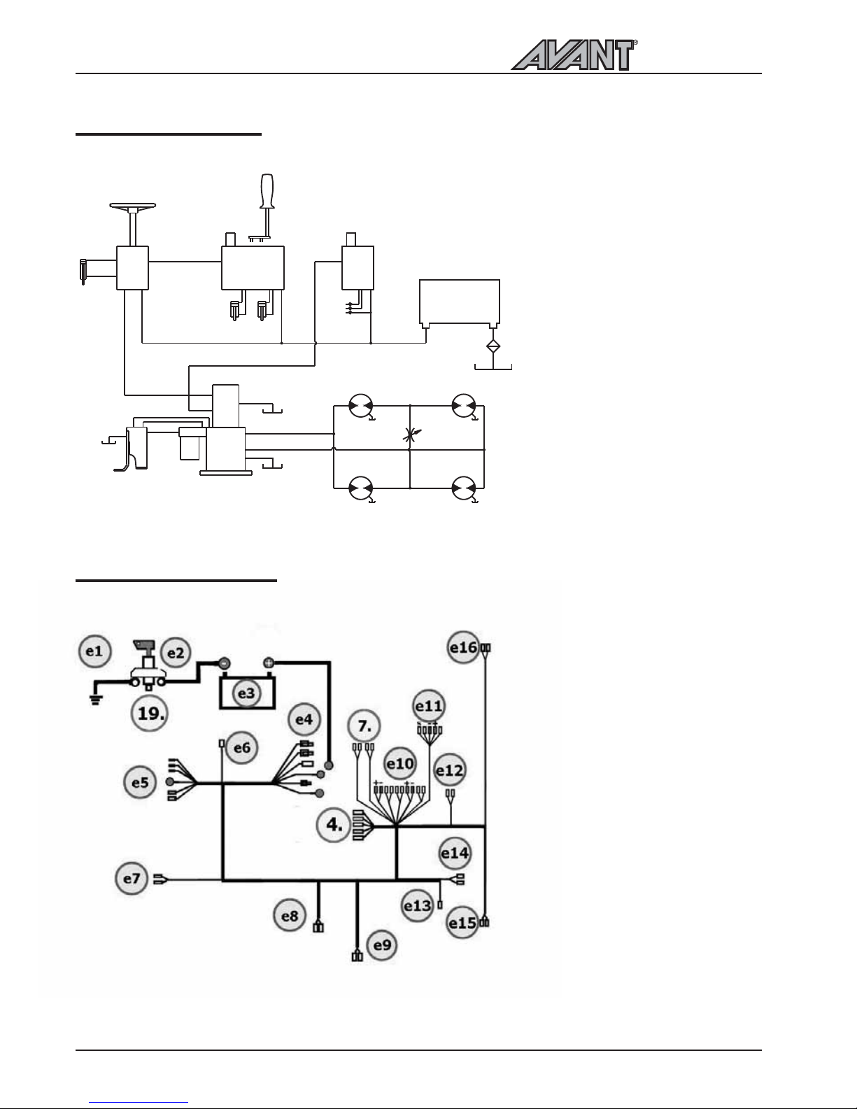
HYDRAULIC SYSTEM
A. Hydrostatic pump, with the feed
pump
B. Double gear pump
C. Driving pedal valve
D. Front wheels
E. Rear wheels
F. F1 -Hydraulic oil return line filter
F2 -Hydraulic oil high pressure filter
G. Orbit Roll steering valve
H. Steering cylinder
I. Gear pump 1. adjustment, pressure
relief valve
J. Boom lift cylinder control valve
K. Bucket tilt cylinder control valve
L. Gear pump 2. adjustment, pressure
relief valve
M. Control valve for the hydraulic
outlet of the accessories
N. Quick couplings of the hydraulic
outlet
O. Oil cooler
P. Drive release valve
ELECTRICAL HARNESS
e1. Earth cable
19. Elecrical main switch
e2. Grounding cable from battery
e3. Battery 12 V
e4. Starter motor
e5. Regulator
e6. Fuel stop valve
e7. Oil cooler fan
e8. Reverse beeper (optional)
e9. Reverse switch (optional)
4. Ignition switch
7. Fuse box
e10. Electric output, light switch,
charge lamp,hour meter,
horn button.
e11. Optional temperature gauge
e12. Horn
e13. Temperature sensor
e14. Thermostat switch for oil-cooler
fan-motor
e15. Working light
e16. Working light
Page 23

Troubleshooting
23
200 Series
TROUBLESHOOTING
Problem
Hydraulic attachment does not
work when the auxiliary
hydraulics control lever is
moved.
Engine does not start.
Attachment hoses will not go
into the quick couplers of the
machine.
The machine moves after
parking brake has been engaged.
Cause
Attachment hoses are not
coupled or they are coupled
wrongly in the quick couplers.
Faulty or damaged quick couplers
(will restrict or stop oil flow)
No fuel
Auxiliary hydraulics control lever
(lever no. 14, see pages 10 and
14) is in locking position.
There is back pressure in the
auxiliary hydraulics line.
The pins of the parking brake
mechanism have not locked
properly in the wheels.
SERVICES MADE
Date Operating hours Remarks
1. _________ __________ ________________________________________________________________
2. _________ __________ ________________________________________________________________
3. _________ __________ ________________________________________________________________
4. _________ __________ ________________________________________________________________
5. _________ __________ ________________________________________________________________
Remedy
Make sure that the hoses are
properly connected into the
quick couplers, change the place
of the hoses if necessary.
Auxiliary hydraulics have
double acting pressure couplers
(female) and a return line (male
coupler) Operating direction
of the attachment depends on
how the hoses are connected
in the quick couplers.
Replace quick couplers.
Fill the tank.
Turn the lever in center
(neutral) position.
Release the pressure by moving
the auxiliary hydraulics control
lever in both directions.
Drive slowly forward or
backward in order to lock the
parking brake.When releasing
the parking brake do this in
opposite order.
Page 24
© 2013 AVANT Tecno Oy. All rights reserved. Printed in Finland
1013
 Loading...