

Page 1

AVALUE TECHNOLOGY, INC.
April 14
th
, 2016
SID-15V-Z37-A1R
Page 2

FCC Statement
THIS DEVICE COMPLIES WITH PART 15 FCC RULES. OPERATION IS
SUBJECT TO THE FOLLOWING TWO CONDITIONS:
(1) THIS DEVICE MAY NOT CAUSE HARMFUL INTERFERENCE.
(2) THIS DEVICE MUST ACCEPT ANY INTERFERENCE RECEIVED INCLUDING
INTERFERENCE THAT MAY CAUSE UNDESIRED OPERATION.
THIS EQUIPMENT HAS BEEN TESTED AND FOUND TO COMPLY WITH THE LIMITS
FOR A CLASS "A" DIGITAL DEVICE, PURSUANT TO PART 15 OF THE FCC RULES.
THESE LIMITS ARE DESIGNED TO PROVIDE REASONABLE PROTECTION AGAINST
HARMFUL INTERFERENCE WHEN THE EQUIPMENT IS OPERATED IN A
COMMERCIAL ENVIRONMENT. THIS EQUIPMENT GENERATES, USES, AND CAN
RADIATE RADIO FREQUENCY ENERGY AND, IF NOT INSTALLED AND USED IN
ACCORDANCE WITH THE INSTRUCTION MANUAL, MAY CAUSE HARMFUL
INTERFERENCE TO RADIO COMMUNICATIONS.
OPERATION OF THIS EQUIPMENT IN A RESIDENTIAL AREA IS LIKELY TO CAUSE
HARMFUL INTERFERENCE IN WHICH CASE THE USER WILL BE REQUIRED TO
CORRECT THE INTERFERENCE AT HIS OWN EXPENSE.
Disclaimer
Avalue Technology Inc. reserves the right to make changes, without notice, to any product,
including circuits and/or software described or contained in this manual in order to improve
design and/or performance. Avalue Technology assumes no responsibility or liability for the use
of the described product(s), conveys no license or title under any patent, copyright, or masks
work rights to these products, and makes no representations or warranties that these products are
free from patent, copyright, or mask work right infringement, unless otherwise specified.
Applications that are described in this manual are for illustration purposes only. Avalue
Technology Inc. makes no representation or warranty that such application will be suitable for
the specified use without further testing or modification.
SID-15V-Z37-A1R User Manual Page 1 of 24 Revision 1.0
Page 3

Life Support Policy
Avalue Technology’s PRODUCTS ARE NOT FOR USE AS CRITICAL COMPONENTS IN
LIFE SUPPORT DEVICES OR SYSTEMS WITHOUT THE PRIOR WRITTEN APPROVAL
OF Avalue Technology Inc.
As used herein:
1. Life support devices or systems are devices or systems which, (a) are intended for surgical
implant into body, or (b) support or sustain life and whose failure to perform, when properly
used in accordance with instructions for use provided in the labeling, can be reasonably
expected to result in significant injury to the user.
2. A critical component is any component of a life support device or system whose failure to
perform can be reasonably expected to cause the failure of the life support device or system,
or to affect its safety or effectiveness.
Customer Services and Support
Each and every Avalue’s product is built to the most exacting specifications to ensure reliable
performance in the harsh and demanding conditions typical of industrial environments. Whether
your new Avalue device is destined for the laboratory or the factory floor, you can be assured that
your product will provide the reliability and ease of operation for which the name Avalue has
come to be known.
Your satisfaction is our primary concern. Here is a guide to Avalue’s customer services. To
ensure you get the full benefit of our services, please follow the instructions below carefully.
We want you to get the maximum performance from your products. So if you run into technical
difficulties, we are here to help. For the most frequently asked questions, you can easily find
answers in your product documentation. These answers are normally a lot more detailed than the
ones we can give over the phone.
If you still cannot find the answer, gather all the information or questions that apply to your
problem, and with the product close at hand, please call Avalue Technology through the number
provided below. Our engineers are well trained and are ready to give you the support you need to
get the most from your Avalue products. In fact, most problems reported are minor and are able
to be easily solved over the phone.
In addition, free technical support is available from Avalue’s engineers every business day. We
are always ready to give advice on application requirements or specific information on the
SID-15V-Z37-A1R User Manual Page 2 of 24 Revision 1.0
Page 4

installation and operation of any of our products. Please do not hesitate to call or e-mail us.
Avalue Technology, Inc.
9 Timber Lane, Marlboro, NJ 07746-1443
Tel: (732) 414-6500
Fax: (732) 414-6501
Information: sales@avalue-usa.com
Service: support@avalue-usa.com
Product Warranty
Avalue warrants to you, the original purchaser, that each of its products will be free from defects
in materials and workmanship for one year from the date of purchase.
This warranty does not apply to any products which have been repaired or altered by persons
other than repair personnel authorized by Avalue, or which have been subject to misuse, abuse,
accident or improper installation. Avalue assumes no liability under the terms of this warranty as
a consequence of such events. Because of Avalue’s high quality-control standards and rigorous
testing, most of our customers never need to use our repair service. If any of Avalue’s products is
defective, it will be repaired or replaced at no charge during the warranty period. For out-ofwarranty repairs, you will be billed according to the cost of replacement materials, service time,
and freight. Please consult your dealer for more details. If you think you have a defective
product, follow these steps:
1. Collect all the information about the problem encountered. (For example, Avalue’s products
model name, hardware & BIOS revision number, other hardware and software used, etc.)
Note anything abnormal and list any on-screen messages you get when the problem occurs.
2. Call your dealer and describe the problem. Please have your manual, product, and any
helpful information available.
3. If your product is diagnosed as defective, obtain an RMA (return material authorization)
number from your dealer. This allows us to process your good return more quickly.
4. Carefully pack the defective product, a complete Repair and Replacement Order Card and a
photocopy proof of purchase date (such as your sales receipt) in a shippable container. A
product returned without proof of the purchase date is not eligible for warranty service.
5. Write the RMA number visibly on the outside of the package and ship it prepaid to your
dealer.
SID-15V-Z37-A1R User Manual Page 3 of 24 Revision 1.0
Page 5

CONTENTS
REVISION HISTORY ....................................................................................................................... 6
1. GETTING STARTED ................................................................................................................. 7
1.1 SAFETY PRECAUTION ........................................................................................................................ 7
1.2 WHAT’S INCLUDED .......................................................................................................................... 7
2. TECHNICAL SPECIFICATIONS ................................................................................................ 8
2.1 SYSTEM SPECIFICATIONS .................................................................................................................. 8
2.2 SYSTEM CONNECTOR OVERVIEW ....................................................................................................... 9
2.2.1 TOP COVER CONNECTORS......................................................................................................... 9
2.2.2 BOTTOM COVER CONNECTORS ................................................................................................. 9
2.2.3 BATTERY CONNECTIONS ........................................................................................................... 9
2.2.4 CONNECTOR OVERVIEW ......................................................................................................... 10
2.3 BATTERY SPECIFICATIONS (OPTIONAL) ............................................................................................ 10
2.3.1 GENERAL SPECIFICATIONS ...................................................................................................... 10
2.3.2 BATTERY HANDLING ............................................................................................................... 11
3. BATTERY INSTALLATION (OPTIONAL) ............................................................................... 12
3.1 PREPARING THE SYSTEM ................................................................................................................. 12
3.2 REMOVING THE BATTERY BRACKET ................................................................................................. 13
3.3 INTEGRATING THE BATTERY ............................................................................................................ 13
3.4 COMPLETING THE INSTALLATION ..................................................................................................... 14
4. CABLE MANAGEMENT ......................................................................................................... 15
4.1 REMOVING CABLE COVER ............................................................................................................... 15
4.2 REMOVING THE BASE FROM THE ARM ............................................................................................. 16
4.3 ROUTING THE CABLES THROUGH THE BASE ...................................................................................... 17
4.4 CABLE ROUTING ON BOTTOM COVER .............................................................................................. 18
4.5 COMPLETING THE INSTALLATION ..................................................................................................... 19
5. UPDATING THE BIOS ........................................................................................................... 19
5.1 PREPARING THE USB KEY ............................................................................................................... 19
5.2 BOOTING TO THE USB KEY ............................................................................................................. 19
5.3 APPLYING THE BIOS UPDATE ......................................................................................................... 19
5.4 LOADING OPTIMIZED DEFAULTS...................................................................................................... 20
6. UPDATING THE FIRMWARE ................................................................................................. 20
6.1 PREPARING THE USB KEY ............................................................................................................... 20
SID-15V-Z37-A1R User Manual Page 4 of 24 Revision 1.0
Page 6

6.2 REBOOTING TO RECOVERY MODE ................................................................................................... 20
6.3 APPLYING THE UPDATE .................................................................................................................. 21
6.4 COMPLETING THE UPDATE .............................................................................................................. 21
7. MECHANICAL DRAWINGS .................................................................................................... 22
7.1 BATTERY DRAWING ....................................................................................................................... 22
7.2 SYSTEM DRAWINGS ....................................................................................................................... 23
SID-15V-Z37-A1R User Manual Page 5 of 24 Revision 1.0
Page 7

REVISION HISTORY
Revision
Number
Descriptions
Date
1.0
First Release
April 14
th
, 2016
SID-15V-Z37-A1R User Manual Page 6 of 24 Revision 1.0
Page 8

1. GETTING STARTED
1.1 SAFETY PRECAUTION
Always completely disconnect the power cord from your chassis whenever you
work with the hardware. Do not make connections while the power is on.
Sensitive electronic components can be damaged by sudden power surges.
Always ground yourself to remove any static charge before touching the CPU
card. Modern electronic devices are very sensitive to static electric charges. As
a safety precaution, use a grounding wrist strap at all times. Place all electronic
components in a static-dissipative surface or static-shielded bag when they are
not in the chassis.
1.2 WHAT’S INCLUDED
Before you begin installing your SID-15V-Z37-A1R, please make sure that
the following materials have been shipped:
1 x SID-15V-Z37-A1R Unit, mounted on Stand w/ Card Reader
1 x ACC-BAT-3SP1-01R
1 x 6ft. Power Cord
SID-15V-Z37-A1R User Manual Page 7 of 24 Revision 1.0
Page 9

2. TECHNICAL SPECIFICATIONS
Component
CPU
Intel Atom Z3735F
Memory
2GB DDR3L
Adapter
+19V DC (65W)
Microphone
1x MIC interface
Operating System
Android 4.4
Storage
Other Storage Device
32GB eMMC
Panel
LCD Panel Size
15.6”
Resolution
1920x1080
Luminance
220 nits
Touch Type
PCAP
Viewing Angle
45°(H+)/ 45°(H-)/ 20°(V+)/ 45°(V-)
External I/O
USB Port
4x USB 2.0
Video Port
1x HDMI
Audio Port
1x Headphone Jack
LAN Port
1x 10/100 Ethernet
Peripheral Devices
1x Smart Card Reader
Expansion Slots
1x Micro SD slot
Mechanical
Power Type
19V DC input
Power Connector Type
DC jack
Li-ion Battery (Optional)
Unit Dimension
19.3 x 11.7 x 8”
Unit Weight
14 lbs. (Including Battery)
Shipping Dimension
23 x 14 x 11”
Shipping Weight
18 lbs. (Including Battery)
Color
Black
Reliability
EMI Test
CE, FCC class B
Operating Temperature
0°C ~ 40°C
Operating Humidity
0%~90% relative humidity, non-condensing
Storage Temperature
-20°C ~ 60°C
2.1 SYSTEM SPECIFICATIONS
SID-15V-Z37-A1R User Manual Page 8 of 24 Revision 1.0
Page 10

2.2 SYSTEM CONNECTOR OVERVIEW
USB
BAT1
SD
USB
DC IN
LAN
USB
HDMI
HP
PWR
BAT2
DOCK
2.2.1 TOP COVER CONNECTORS
FIG. 2A: SYSTEM TOP VIEW, NO C OVER
2.2.2 BOTTOM COVER CONNECTORS
FIG. 2B: SYSTEM BOT TOM VI EW, NO COVER
2.2.3 BATTERY CONNECTIONS
FIG. 2C: BATT ERY BOARD, TO P VIEW
SID-15V-Z37-A1R User Manual Page 9 of 24 Revision 1.0
Page 11

2.2.4 CONNECTOR OVERVIEW
Label
PWR
Power Button
HP
Audio line-out connector
HDMI
HDMI Connector
USB
4 x USB 2.0 Connector
LAN
RJ-45 Ethernet
DC IN
DC Power-In Connector
SD
Micro SD Card Slow
BAT1
Motherboard Battery Connector
BAT2
Auxiliary Battery Board Battery Connector
DOCK
Optional Battery Docking Connector
General
Battery Model Number
ACC-BAT-3S1P-01R
Battery Cell Type
Li-Ion Rechargeable Cell
Nominal Voltage
AVG. 10.8V
Charging Voltage
MAX. 12.6V
Typical Capacity
2400 mAh 25ºC±2ºC
Minimum Capacity
2215 mAh at 25ºC, by 0.2C 443 mA discharge
Standard Charging
12.6 V / CC: 0.5C, 1106 mA at 25ºC ± 2ºC
Terminal charge condition: <117 mA
Maximum Charging
12.6 V / CC: 0.9C, 2000 mA at 25ºC ± 2ºC
Terminal charge condition: <117 mA
Charge rates >0.86 C are NOT recommended.
Pre-Charge Current
128 mA (When cell voltage under 3.0V or
temperature under 10 ºC)
Standard Continuous
Discharge Current
0.2 C 443 mA
Continuous discharging to 8.25 V
Maximum Continuous
Discharge Current
1.355 C 3000 mA
Continuous discharging to 8.25 V
Charge Termination
Condition
When the pack voltage is 12.6 V, and the
charge current is less than or equal to 117 mA
the charging should be terminated.
2.3 BATTERY SPECIFICATIONS (OPTIONAL)
2.3.1 GENERAL SPECIFICATIONS
SID-15V-Z37-A1R User Manual Page 10 of 24 Revision 1.0
Page 12

Relative State Of Charge = 100 %
When the Relative State Of Charge is under
95%, the pack can re-start charging.
Discharge Termination
Condition
When pack voltage is less than or equal to
8.25 V, the discharging should be terminated.
Operating Temperature
Charge: 0 ºC~ 45 ºC, 85%RH Max
Discharge -10 ºC~ 60 ºC, 85%RH Max
Storage Temperature
If the battery packs are subject to storage for
such a long term, it is recommended to
recharge the battery pack periodically, every
two-months.
1 Month -20~60 ºC, 85 %RH Max
3 Months -20~45 ºC, 85 %RH Max
1 Year -20~20 ºC, 85 %RH Max
Thermistor
NTC 10K B=3435 @25℃
FCC Range
1993.5 mAh to 2784 mAh for 0.2C Charge and
Discharge at 25 ºC
Electrical
Life Cycle
Discharge capacity (500) Cycle is greater than
or equal to 80 % 1772 mAh
Ambiance Temp: 25±3ºC.
A battery unit shall be repeated 500
charge/discharge cycles, charged at CC-CV
1108 mA - 12.6 V. cut-off 117 mAh
discharged at 1108 mA. Continuously down
to 8.25 V. cut-off voltage.
Remark: Rest 20 min after charge
Rest 20 min after discharge
ESD Requirement
Contact discharge ±4KV, Air discharge ±8KV
Dynamic Test
High level: 3000 mA
Low level: 300 mA
Discharged continuously down to 8.25 V Cutoff Voltage
No rupture, fire, smoke, explosion, leakage
and protection.
2.3.2 BATTERY HANDLING
SID-15V-Z37-A1R User Manual Page 11 of 24 Revision 1.0
To ensure safety and maximum life of your product please follow the
precautions outlined below:
Avoid shorting the battery
Do not immerse in water.
Page 13

Do not disassemble or deform the battery
Do not expose to, or dispose of the battery in fire.
Avoid excessive physical shock or vibration.
Keep out of the reach of children.
Never use a battery that appears to have suffered abuse.
Store in a cool, dry, and well-ventilated area.
Dispose of in accordance with local regulations. Regulations vary for
different countries.
3. BATTERY INSTALLATION (OPTIONAL)
3.1 PREPARING THE SYSTEM
FIG. 3A: SYSTEM ISO MET RIC BACK VIEW, OPENING TH E TOP COVE R
Please make sure the unit is unplugged and powered off.
Lay the unit flat, screen side down, on a smooth surface.
Locate and open the hinged Top Cover (highlighted in blue).
Once opened, locate the battery bracket.
SID-15V-Z37-A1R User Manual Page 12 of 24 Revision 1.0
Page 14
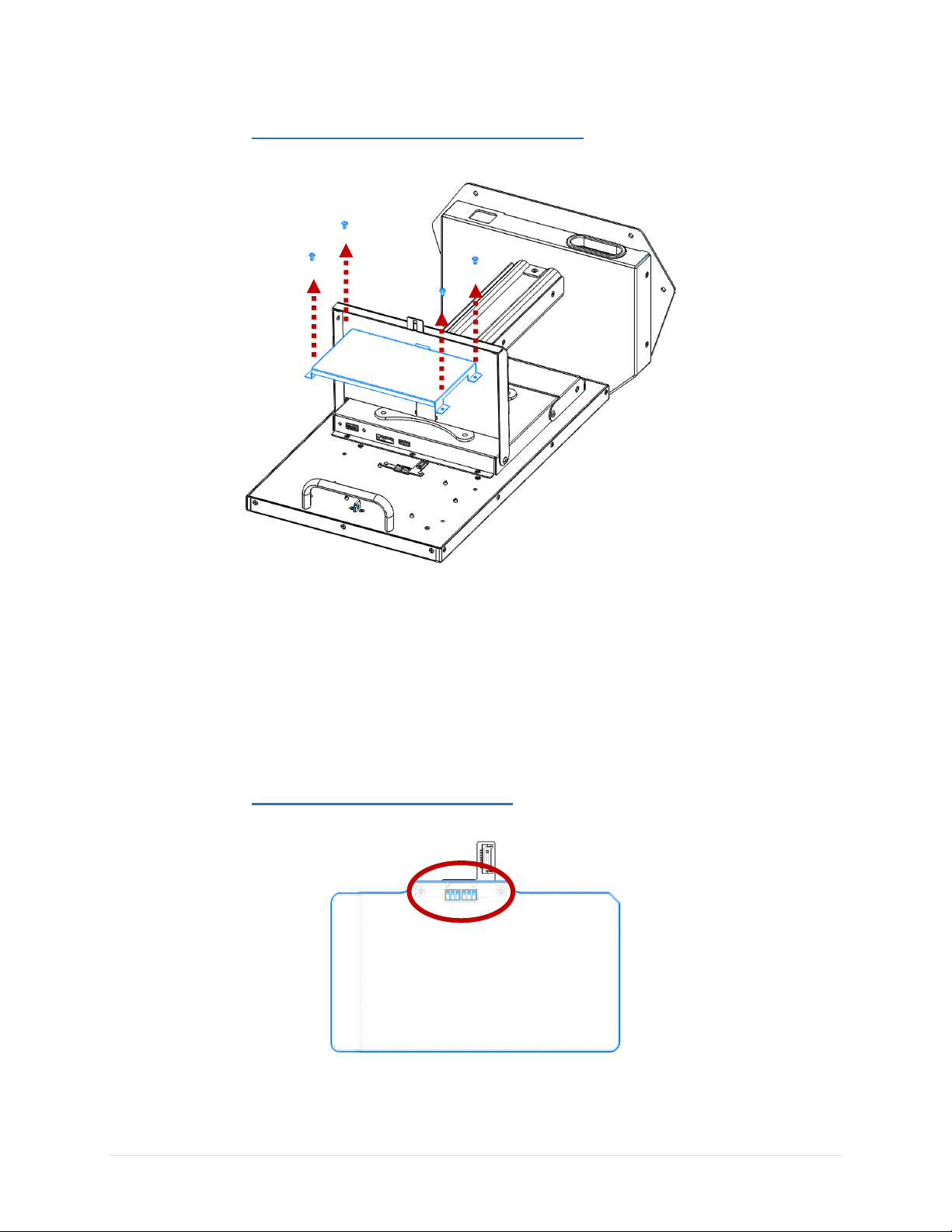
3.2 REMOVING THE BATTERY BRACKET
FIG. 3B: BATTERY BRACK ET REM OVAL
Remove the 4 screws (M3x5) that secure the battery bracket to the
system.
Remove the bracket from the system.
Locate the battery connection board under the bracket.
3.3 INTEGRATING THE BATTERY
FIG. 3C: BATTERY MOU NTED ON BOARD
SID-15V-Z37-A1R User Manual Page 13 of 24 Revision 1.0
Page 15

FIG. 3D: BATTERY AN D BATTE RY BRACK ET INSTALL ATIO N
Place the battery on the DOCK connection on the system with the
smooth side up and the tab facing the center of the system. Please
make sure that the contacts from the battery to the board are lined up
properly (refer to Fig. 3C for visual reference).
Mount the battery bracket to the system using the 4 screws we
previously removed.
NOTE: It may be easier to integrate the battery into the battery bracket
first, then mount the bracket on the system.
3.4 COMPLETING THE INSTALLATION
Once complete, close the top cover. The top cover will secure itself to
the system through a magnetic connection.
The system can now be placed upright on a flat, stable surface.
Plug in the power cord and turn the system on. Verify the battery is
being recognized by the system and is charging in Settings>Battery.
SID-15V-Z37-A1R User Manual Page 14 of 24 Revision 1.0
Page 16

4. CABLE MANAGEMENT
4.1 REMOVING CABLE COVER
FIG. 4A: STAN D ISOMET RIC FRON T VIEW, REMO VI NG CABLE COVE R
Locate the Cable Cover on the Base Stand (highlighted in blue)
Remove the 4 screws that keep the cover in place and pull the cover
off of the Arm.
SID-15V-Z37-A1R User Manual Page 15 of 24 Revision 1.0
Page 17

4.2 REMOVING THE BASE FROM THE ARM
FIG. 4B: BOTTO M AN D ISO MET RIC FRO NT VIE W, REMOVI NG BASE F ROM ARM
Locate the 3 screws that hold the Arm to the Base. There are 2
underneath the unit, and 1 along the backside of the arm.
The arm should slide out of the hole in the base
NOTE: Please use caution while other cables may be routed through
this hole.
SID-15V-Z37-A1R User Manual Page 16 of 24 Revision 1.0
Page 18

4.3 ROUTING THE CABLES THROUGH THE BASE
FIG. 4C: CABLE ROUTIN G THRO UGH STAND PASS-THROU GH
Route the cables through the pass-through hole along the backside of
the unit and up through the center hole that the Arm was taken out of.
NOTE: This pass-through hole should be lined with a plastic cable
bushing to prevent cable wear.
Gather the cables to the front of the hole, and insert the Arm back into
the hole. Please use caution when doing this and make sure that no
cables will be pinched between the bottom of the Arm and the
bottom base plate. The cables should run through the passthrough along the back and hug around the arm up the top of the
Bases hole opening.
Mount the Arm back onto the Base using the 3 screws that were
removed earlier.
SID-15V-Z37-A1R User Manual Page 17 of 24 Revision 1.0
Page 19

4.4 CABLE ROUTING ON BOTTOM COVER
FIG.4D: SYS TEM ISOM ETRIC BACK VIEW , OPENIN G TH E BOTTOM COVER
Locate and open the hinged Bottom Cover (highlighted in blue)
FIG. 4E: SYSTEM ISO MET RIC BACK VIEW, CABLE ROU TING THROUGH BOTTOM COVER
Route the cables through the cable pass-through hole on the cover and
attach the cables to the system’s I/O.
NOTE: This hole should be lined with a plastic cable bushing to
prevent wear on the cable. If there is not bushing on the unit, one is
available inside the accessory box.
Close the Bottom Cover. As illustrated in Fig. 4E, leave several inches
of extra cable slack in the door. This will prevent any strain on the
cable if the display was tilted on the mount.
SID-15V-Z37-A1R User Manual Page 18 of 24 Revision 1.0
Page 20

4.5 COMPLETING THE INSTALLATION
Once complete, close and lock the Bottom Cover.
Reinstall the Cable Cover on the Arm. Make sure that all of the cables
are not visible and hidden properly behind the Cover.
5. UPDATING THE BIOS
After installing your SID-15V-Z37-A1R assembly, please make sure all of your cables
are installed properly. After powering on the unit and verifying the operating system
loads, it may be recommended to update the BIOS before initial functional use.
5.1 PREPARING THE USB KEY
To install the most recent BIOS update on the system, please have a USB key
at hand, formatted with a FAT32 file system. The most recent BIOS update
folder must be downloaded and decompressed on the USB’s root folder in
order for the system to function properly.
5.2 BOOTING TO THE USB KEY
Plug the USB key into a USB port of SID-15V and power on the system.
Please press “F12” repeatedly while the system is turning on to get into the
boot manager of the BIOS. Here, please choose the USB Device as the boot
device. This will load the EFI shell on the USB key.
5.3 APPLYING THE BIOS UPDATE
Once at the EFI shell, please type in “fs1:” to gain access to the USB key. To
change directories to the appropriate folder “\EFI\BOOT”, please use the
following commands:
>cd EFI
>cd boot
SID-15V-Z37-A1R User Manual Page 19 of 24 Revision 1.0
Page 21

To Flash the BIOS for Android or Linux, please run command
“BCX11x64.nsh”.
NOTE: Please do not remove power from the system while the BIOS is
flashing.
5.4 LOADING OPTIMIZED DEFAULTS
Once the BIOS has completed updating, the system will reboot automatically.
After the system reboots, please press “F2” to get into the BIOS Setup Menu.
Here, highlight to the following:
“>Exit>Load Optimized Defaults>Yes> Exit Saving Changes”
The system will now reboot again to the main Operating System with the
correct BIOS revision.
6. UPDATING THE FIRMWARE
After installing your SID-15V-Z37-A1R assembly, please make sure all of your cables
are installed properly. After powering on the unit and verifying the operating system
loads, it may be recommended to update the Android firmware before initial functional
use.
6.1 PREPARING THE USB KEY
To install the most recent Android Firmware on the system, please have a
USB key at hand, formatted with a FAT32 file system. The most recent OTA
Update file must be downloaded and the compressed folder must be on the
USB’s root folder in order for the system to function properly.
6.2 REBOOTING TO RECOVERY MODE
Power on the SID-15V-Z37-A1R System and load into the Android OS.
Navigate to the “Settings” page. Scrolling down to the bottom of the page,
click on the “About Tablet” page. Here, you will find the “Software Update”
option to click on. Please press the “Reboot into recovery mode” button to
get into Android recovery mode.
SID-15V-Z37-A1R User Manual Page 20 of 24 Revision 1.0
Page 22

6.3 APPLYING THE UPDATE
Select the “Apply update from USB” option while in the Android system
recovery menu. Next, select the most recent OTA image file that was
previously copied on USB drive.
6.4 COMPLETING THE UPDATE
After completing the update, the system will return to the Android system
recovery menu. Please select “Reboot system now” to reboot the system and
get into the newly updated Android OS. Please note you may need to unplug
USB disk before you reboot the system.
SID-15V-Z37-A1R User Manual Page 21 of 24 Revision 1.0
Page 23

7. MECHANICAL DRAWINGS
7.1 BATTERY DRAWING
SID-15V-Z37-A1R User Manual Page 22 of 24 Revision 1.0
Page 24

7.2 SYSTEM DRAWINGS
SID-15V-Z37-A1R User Manual Page 23 of 24 Revision 1.0
 Loading...