


Part No. E201715W3A0R
Open Frame 15.6”
Series
OPC-15W3
Quick Reference Guide
1st Ed – 23 August 2012
Copyright Notice
Copyright 2012 Avalue Technology Inc., ALL RIGHTS RESERVED.

Open Frame 15.6” Series
2 Open Frame 15.6” Series Quick Reference Guide
Contents
1. Getting Started ........................................................................................................ 3
1.1 Safety Precautions .................................................................................................... 3
1.2 Packing List ............................................................................................................... 3
1.3 System Specifications ............................................................................................... 4
1.4 System Overview ...................................................................................................... 6
1.4.1 Front View ................................................................................................................................ 6
1.4.2 Rear IO View ........................................................................................................................... 7
1.4.3 Bottom IO View ........................................................................................................................ 8
1.4.4 Side IO ..................................................................................................................................... 9
1.5 System Dimensions ................................................................................................ 10
2. Hardware Configuration ....................................................................................... 11
2.1 Jumper and Connector Setting................................................................................ 12
2.1.1 Jumper Setting....................................................................................................................... 12
2.1.2 Connector Setting .................................................................................................................. 13
2.2 Hard Disk, Memory & Expansion Cards Installation ................................................ 14
2.3 Turn on the System ................................................................................................. 18
2.4 Enter BIOS Menu, Select Booting Devices ............................................................. 18
2.5 System Integration & Mounting ............................................................................... 19

Quick Reference Guide
Open Frame 15.6” Series Quick Reference Guide
3
1. Getting Started
1.1 Safety Precautions
Warning!
Always completely disconnect the power cord from your
chassis whenever you work with the hardware. Do not
make connections while the power is on. Sensitive
electronic components can be damaged by sudden power
surges. Only experienced electronics personnel should
open the PC chassis.
Caution!
Always ground yourself to remove any static charge before
touching the CPU card. Modern electronic devices are very
sensitive to static electric charges. As a safety precaution,
use a grounding wrist strap at all times. Place all electronic
components in a static-dissipative surface or static-shielded
bag when they are not in the chassis.
1.2 Packing List
1 x OPC-15W3 Series Open Frame PC
1 x Quick Reference Guide
1 x DVD-ROM (For all drivers)
Other major components include the followings:
— 1 x 19V/65W AC-DC Adapter
— 1 x Power Cord
— 2 x Screws (for hard disk drive bracket)
— 1 x Sponge (to paste on hard disk drive)

Open Frame 15.6” Series
4 Open Frame 15.6” Series Quick Reference Guide
1.3 System Specifications
Model
OPC-15W3
System Type
Open Frame All-In-One System
Display
15.6” TFT-LCD
1920x1080 Resolutions
LED Backlight
300 cd/m2 White Luminance
500:1 Contrast Ratio
Touch Screen
Projected Capacitive Touch
10-Point Multi-touch
EETI Controller
Main System
Customized 945GSE Main board
- Processor
Intel® Atom™ N270 Processor
- Chipsets
Mobile Intel® 945GSE Express Chipset
- Memory
Dual channel DDR2 533/667MHz
Two SODIMM sockets
Maximum 4GB Capacity
- Audio
Realtek® ALC888 Audio CODEC
- Ethernet
Intel® 82574L Gigabit Ethernet Controller
- Storage
2.5” SATA Hard Disk Drive Bay
CF Socket
I/O Interface
1 * RJ-45
1 * DVI
1 * HDMI
4 * USB 2.0 (Type-A Female)
1 * Earphone
1 * Microphone
Optional I/O Interface
2 * RJ-45
4 * USB 2.0 (Type-A Female)
1 * RS-232
1 * RS-232/422/485
Optional Peripherals
1 * 1.3M Camera or 2.0M Auto Focus Camera
Speakers
2 * 2W Speakers
Mounting
VESA 75 (M6)
Power Requirement
12-19V Wide Range DC Input / Optional 12-24V Wide Range DC Input
Power Consumption
19V@1.15A , 26.98W
Accessory
19V 65W Adapter
Operating Temperature
0 ~40C (System Fanless)

Quick Reference Guide
Open Frame 15.6” Series Quick Reference Guide
5
Storage
Temperature
-20~70C
Chassis Material
SECC with Nickel Coating Treatment
Weight
4.53Kgs
OS Support
Windows XP & Windows XP Embedded (Not Multi-touch)
Windows 7 & Windows Embedded 7 (10-Point Multi-touch)

Open Frame 15.6” Series
6 Open Frame 15.6” Series Quick Reference Guide
1.4 System Overview
1.4.1 Front View
Functions
Descriptions
Note
1. 15.6” LCD
16:9 1920x1080 display
2. 15.6” PCAP Touch Screen
Multi-touch touch screen
3. Camera
1.3M / 2.0M Camera
Optional
4. Mounting Brackets
4 mounting brackets
Customizable

Quick Reference Guide
Open Frame 15.6” Series Quick Reference Guide
7
1.4.2 Rear IO View
Connectors
Label
Function
Note
1. TV
TV Antenna Connector
Optional
2. USB
USB 2.0 Type-A Female Connector
3. LAN
RJ-45 Connector
4. DC
DC Ø5.5x Ø 2.5x9.5 mm Power Input Jack
5. HDMI
HDMI Output
6. DVI-I
DVI-I Output

Open Frame 15.6” Series
8 Open Frame 15.6” Series Quick Reference Guide
1.4.3 Bottom IO View
Connectors
Label
Function
Note
1~2. LAN
Extra LAN (RJ-45) through add-on card
Optional
3. COM
RS-232 (DB9)
Optional
4. COM
RS-232/422/485 (DB9)
Optional
5. EP
Earphone 3.5mm Jack
6. MIC
Microphone 3.5mm Jack
7~9. USB
Type-A Female Connector
10~11.USB
Type-A Female Connector
Optional
Quick Reference Guide
Open Frame 15.6” Series Quick Reference Guide
9
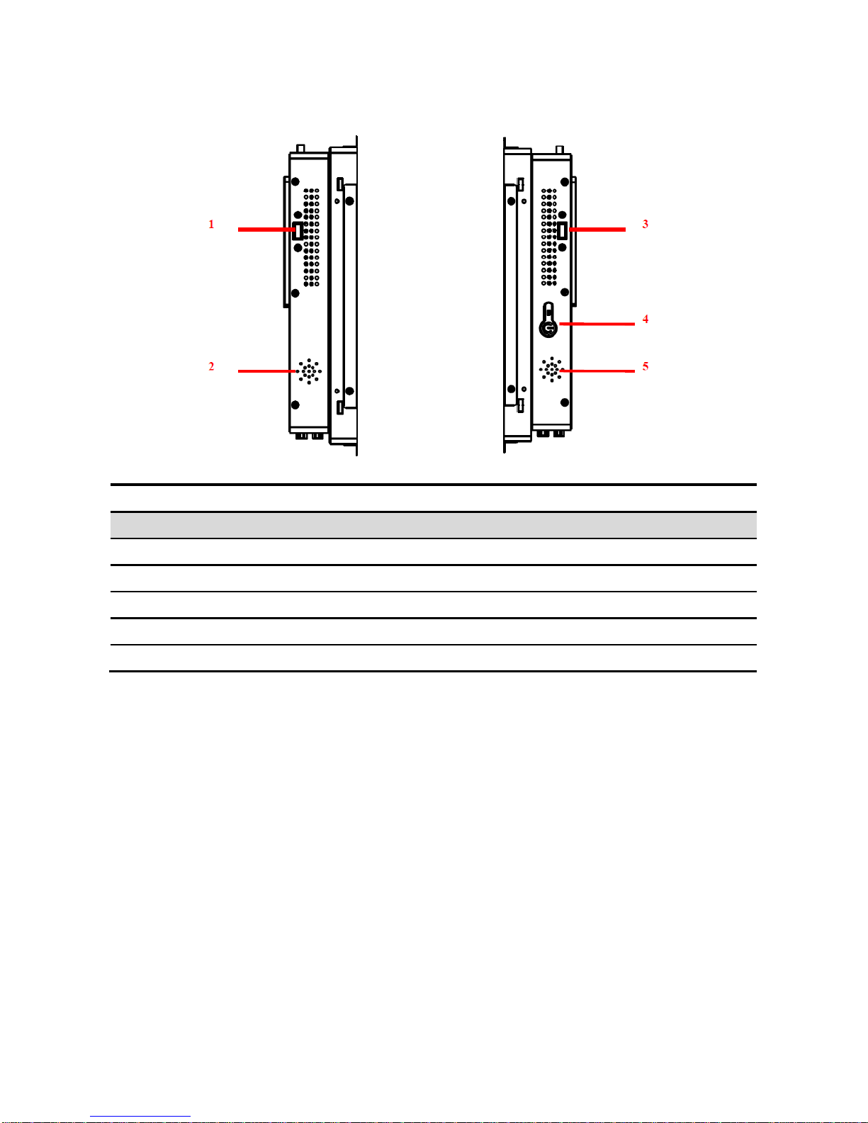
1.4.4 Side IO
Connectors
Label
Function
Note
1. USB
Right Side Type-A Female Connector
Optional
2. SPK
Right Channel 2W System Speaker
3. USB
Left Side Type-A Female Connector
Optional
4. PWR
Power button with green LED indicator
5. SPK
Left Channel 2W System Speaker
Open Frame 15.6” Series
10 Open Frame 15.6” Series Quick Reference Guide
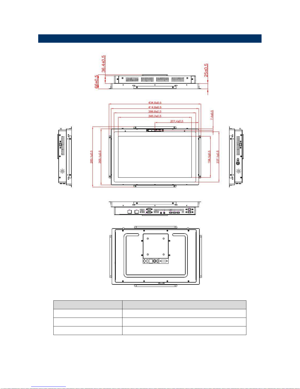
1.5 System Dimensions
Dimensions (mm)
Descriptions
434.8 x 285.1 x 66
System dimension with mounting brackets
414.8 x 265.1 x 66
System dimension without mounting brackets
345.2 x 194.5
Display / Touch screen active area

Quick Reference Guide
Open Frame 15.6” Series Quick Reference Guide
11
2. Hardware
Configuration
Note: If you need more information, please visit our website:
http://www.avalue.com.tw
Open Frame 15.6” Series
12 Open Frame 15.6” Series Quick Reference Guide
2.1 Jumper and Connector Setting
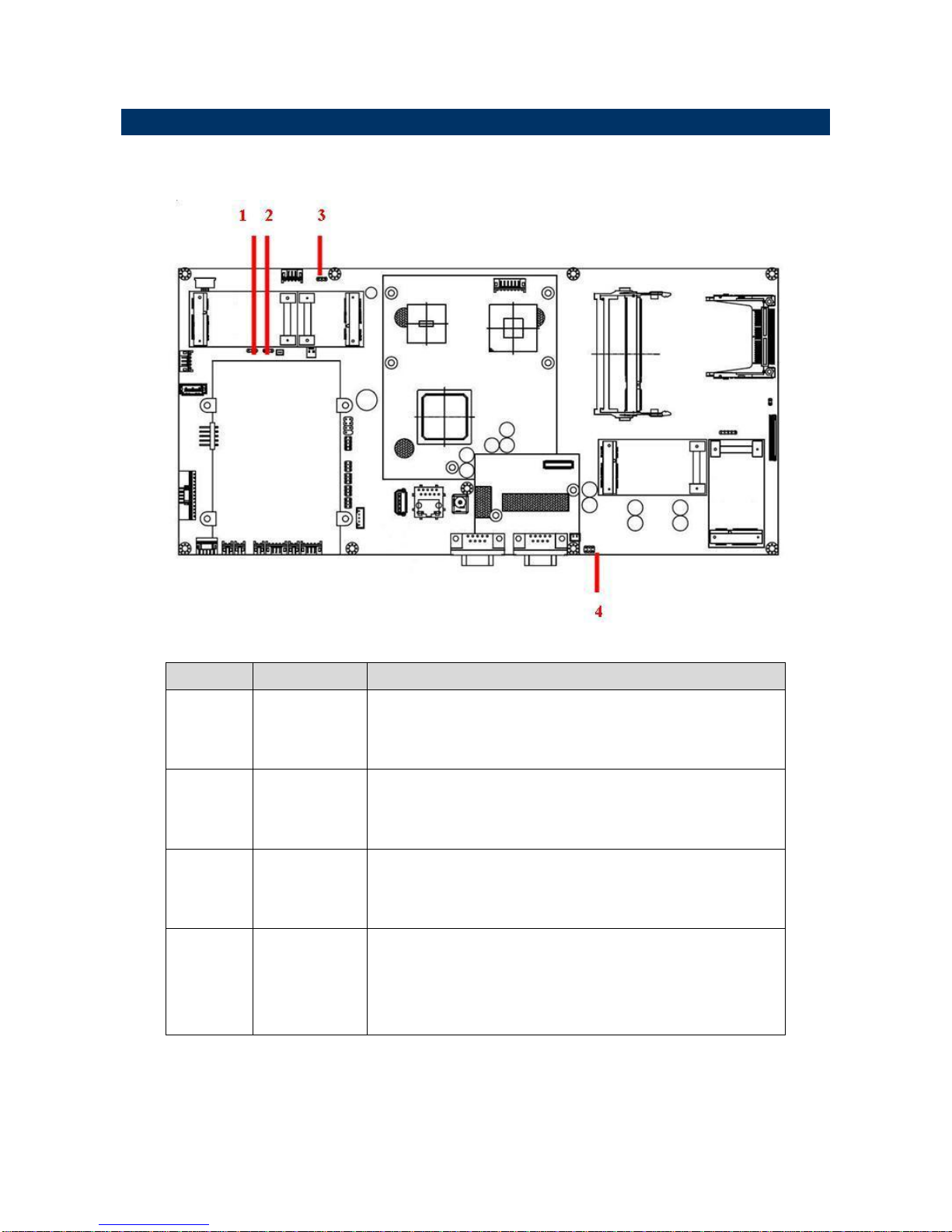
2.1.1 Jumper Setting
Item No
Label
Function
1
JAT1
Power Mode
1-2 : AT Mode
2-3: ATX Mode (Factory Default)
2
JCMOS1
CMOS Clear
1-2: Normal (Factory Default)
2-3: Clear CMOS
3
JWIFI(PWR)
JWIFIA1 Socket Power Choices
2-3: 3.3V (Factory Default)
1-2: 5V
4
JRISW1
Serial Port RI Pin Setting (For COM2 ONLY)
1-2: RI (Factory Default)
3-4: +12V
5-6: +5V
* Jumpers/Pin Headers not mentioned in the above table but appearing on the board are for technical staff
use ONLY. Do not use these jumpers/pin headers without consulting us first.
Quick Reference Guide
Open Frame 15.6” Series Quick Reference Guide
13
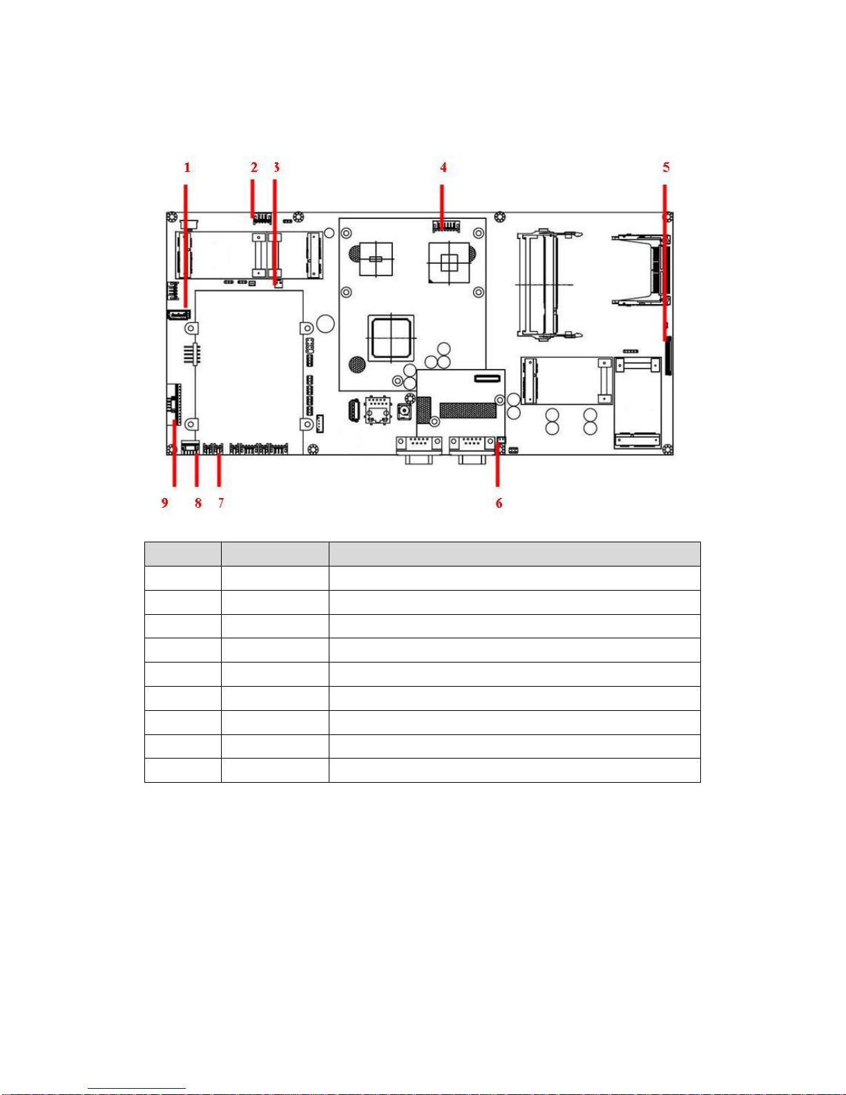
2.1.2 Connector Setting
Item No
Label
Function
1
JSATA1
SATA data signal
2
JWEB1
USB signal & 5V power to optional camera
3
JSATAPWR1
+5V
4
JIC1
USB signal & 5V power to PCAP touch screen
5
JLVDS1
For LCD signal and power
6
JSPK2
For right channel speaker
7
JSPK1
For left channel speaker
8
JFRONT1
For power switch
9
JSIDEOUT1
For USB/MIC/EP board
,
* Jumpers/Pin Headers not mentioned in the above table but appearing on the board are for technical staff
use ONLY. Do not use these jumpers/pin headers without consulting us first.

Open Frame 15.6” Series
14 Open Frame 15.6” Series Quick Reference Guide
2.2 Hard Disk, Memory & Expansion Cards Installation
2.2.1 Remove Top Cover
Step 1. Remove 4 screws (red dots) from the heat sink.*
*These 4 screws are different from all others screws in the system. Do not mix these 4 screws with others.
Step 2. Remove 2 screws (green dots) from the DVI connector.
Step 3. Remove 6 screws (red dots) from the top of the chassis.
Step 4. Remove 8 screws (blue dots) from the top of the chassis.
Step 5. Lift and remove the top cover.*
*Remove the top cover carefully if the TV antenna cable is attached to the TV tuner card.

Quick Reference Guide
Open Frame 15.6” Series Quick Reference Guide
15
2.2.2 Install Hard Disk Driver
Step 1. From the accessory bag, find the 2 screws and use them to assemble the hard disk
drive with the bracket.
Step 2. Insert the hard disk drive into the hard disk bay.
Step 3. Use 2 screws (red dots) to secure the hard disk drive to the hard disk bay.
Step 4. Connect the preloaded SATA power cable & SATA signal cable to the hard disk.
2.2.3 Install Memory

Open Frame 15.6” Series
16 Open Frame 15.6” Series Quick Reference Guide
Insert DDR2 SO-DIMM memory modules into the memory sockets.
* You can insert two 2GB DDR2 533/667 SO-DIMM modules on the memory sockets to reach the maximum
support of 4GB memory.

Quick Reference Guide
Open Frame 15.6” Series Quick Reference Guide
17
2.2.4 Install Expansion Card
You can use these four (4) expansion sockets with cards for your applications.
Item No
Label
Function
1
JDTVB1
Mini-PCIE (PCIE x1 & USB)
2
JWIFIA1
Mini-Card (USB ONLY)
3
JMPCIEA1
Mini-PCIE (PCIE x1 & USB)
4
JMPCIE2B
Mini-PCIE (PCIE x1 ONLY)

Open Frame 15.6” Series
18 Open Frame 15.6” Series Quick Reference Guide
2.3 Turn on the System
Step 1. Plug the adapter into the DC jack.*
Step 2. Press the power button on the left side of the system to turn on the system. A green
led indicator will show the system is ON.
2.4 Enter BIOS Menu, Select Booting Devices
Enter BIOS Menu
1) Plug USB keyboard on the USB 2.0 port.
2) Press the “Power Button” to start the system.
3) Press “DEL” key when seeing the boot up screen to enter the BIOS main menu.
* On the top right corner of the display, make sure you press DEL key when you see the BIOS post code reaches 75.
Select Booting Devices
1) Plug USB keyboard on the USB 2.0 port.
2) Press the “Power Button” to start the system.
3) Press “F12” key when seeing the boot up screen to enter the boot-up device dialog box.

Quick Reference Guide
Open Frame 15.6” Series Quick Reference Guide
19
2.5 System Integration & Mounting
(1) VESA Mount
You can use VESA mounting to assemble OPC-15W3 inside the cabinet of your
applications.
Suggested screws
Type of Screws
Quantity
Drawing
M6x10
4
(2) Mounting Brackets
Open Frame 15.6” Series
20 Open Frame 15.6” Series Quick Reference Guide
Ordering Information
Standard Products
Item No
Part Number
Product Descriptions
Note
1
OPC-15W3-B1T
15.6" Full HD 1920x1080 PCAP
(Multi-touch) Atom N270 Open
Frame Panel PC
OPC/15.6"/PCT/AtomN270/SPK
(Not include
Memory/Hard
Disk/Camera)
Expansion Options
Item No
Optional Features
1
Add 1.3M/2.0M Camera Modules
2
Add two LAN ports
3
Add 1~ 4 USB Ports
4
Add wireless module with Antenna
5
Add front bezel with/without water proof
6
Add customized mounting brackets
…
Other features not list above…
Please contact us for the above expansion options.
 Loading...