


Part No. E2017LP17A1R
LPC-17 Series
Fanless 17” SXGA TFT
Multifunctional Touch Panel PC
Quick Reference Guide
2nd Ed – 19 November 2013
Copyright Notice
Copyright 2013 Avalue Technology Inc., ALL RIGHTS RESERVED.

LPC-17 Series
2 LPC-17 Series Quick Reference Guide
FCC Statement
THIS DEVICE COMPLIES WITH PART 15 FCC RULES. OPERATION IS
SUBJECT TO THE FOLLOWING TWO CONDITIONS:
(1) THIS DEVICE MAY NOT CAUSE HARMFUL INTERFERENCE.
(2) THIS DEVICE MUST ACCEPT ANY INTERFERENCE RECEIVED INCLUDING
INTERFERENCE THAT MAY CAUSE UNDESIRED OPERATION.
THIS EQUIPMENT HAS BEEN TESTED AND FOUND TO COMPLY WITH THE LIMITS
FOR A CLASS "A" DIGITAL DEVICE, PURSUANT TO PART 15 OF THE FCC RULES.
THESE LIMITS ARE DESIGNED TO PROVIDE REASONABLE PROTECTION AGAINST
HARMFUL INTERFERENCE WHEN THE EQUIPMENT IS OPERATED IN A
COMMERCIAL ENVIRONMENT. THIS EQUIPMENT GENERATES, USES, AND CAN
RADIATE RADIO FREQUENCY ENERGY AND, IF NOT INSTALLED AND USED IN
ACCORDANCE WITH THE INSTRUCTION MANUAL, MAY CAUSE HARMFUL
INTERFERENCE TO RADIO COMMUNICATIONS.
OPERATION OF THIS EQUIPMENT IN A RESIDENTIAL AREA IS LIKELY TO CAUSE
HARMFUL INTERFERENCE IN WHICH CASE THE USER WILL BE REQUIRED TO
CORRECT THE INTERFERENCE AT HIS OWN EXPENSE.
Notice
This guide is designed for experienced users to setup the system within the shortest time.
For detailed information, please always refer to the electronic user's manual.
Copyright Notice
Copyright 2013 Avalue Technology Inc., ALL RIGHTS RESERVED.
No part of this document may be reproduced, copied, translated, or transmitted in any form
or by any means, electronic or mechanical, for any purpose, without the prior written
permission of the original manufacturer.
Trademark Acknowledgement
Brand and product names are trademarks or registered trademarks of their respective
owners.
Disclaimer
Avalue Technology Inc. reserves the right to make changes, without notice, to any product,
including circuits and/or software described or contained in this manual in order to improve
design and/or performance. Avalue Technology assumes no responsibility or liability for the
use of the described product(s), conveys no license or title under any patent, copyright, or
masks work rights to these products, and makes no representations or warranties that

Quick Reference Guide
LPC-17 Series Quick Reference Guide
3
these products are free from patent, copyright, or mask work right infringement, unless
otherwise specified. Applications that are described in this manual are for illustration
purposes only. Avalue Technology Inc. makes no representation or warranty that such
application will be suitable for the specified use without further testing or modification.
Life Support Policy
Avalue Technology’s PRODUCTS ARE NOT FOR USE AS CRITICAL COMPONENTS IN
LIFE SUPPORT DEVICES OR SYSTEMS WITHOUT THE PRIOR WRITTEN APPROVAL
OF Avalue Technology Inc.
As used herein:
1. Life support devices or systems are devices or systems which, (a) are intended for
surgical implant into body, or (b) support or sustain life and whose failure to perform,
when properly used in accordance with instructions for use provided in the labeling, can
be reasonably expected to result in significant injury to the user.
2. A critical component is any component of a life support device or system whose
failure to perform can be reasonably expected to cause the failure of the life
support device or system, or to affect its safety or effectiveness.
A Message to the Customer
Avalue Customer Services
Each and every Avalue’s product is built to the most exacting specifications to ensure
reliable performance in the harsh and demanding conditions typical of industrial
environments. Whether your new Avalue device is destined for the laboratory or the factory
floor, you can be assured that your product will provide the reliability and ease of operation
for which the name Avalue has come to be known.
Your satisfaction is our primary concern. Here is a guide to Avalue’s customer services. To
ensure you get the full benefit of our services, please follow the instructions below carefully.
Technical Support
We want you to get the maximum performance from your products. So if you run into
technical difficulties, we are here to help. For the most frequently asked questions, you can
easily find answers in your product documentation. These answers are normally a lot more
detailed than the ones we can give over the phone. So please consult the user’s manual
first.
To receive the latest version of the user’s manual; please visit our Web site at:
http://www.avalue.com.tw/

LPC-17 Series
4 LPC-17 Series Quick Reference Guide
Contents
1. Getting Started ........................................................................................................ 5
1.1 Safety Precautions .................................................................................................... 5
1.2 Packing List ............................................................................................................... 5
1.3 System Specifications ............................................................................................... 6
1.4 System Overview ................................................................................................ ...... 8
1.4.1 Front View ................................................................................................................................ 8
1.4.2 Rear View ................................................................................................................................ 8
1.5 System Dimensions ................................................................................................ 10
1.5.1 LPC-1705 Front and Rear side .............................................................................................. 10
1.5.2 LPC-1707 Front and Rear side .............................................................................................. 11
1.5.3 LPC-17A4 Front and Rear side ............................................................................................. 12
2. Hardware Configuration ....................................................................................... 13
2.1 LPC 17 Series connector mapping .......................................................................... 14
2.1.1 Serial Port 1 connector (COM1).............................................................................................. 14
2.2 Installing Hard Disk & Memory ................................................................................ 15
Quick Reference Guide
LPC-17 Series Quick Reference Guide
5
1. Getting Started
1.1 Safety Precautions
Warning!
Always completely disconnect the power cord from your
chassis whenever you work with the hardware. Do not
make connections while the power is on. Sensitive
electronic components can be damaged by sudden power
surges. Only experienced electronics personnel should
open the PC chassis.
Caution!
Always ground yourself to remove any static charge before
touching the CPU card. Modern electronic devices are very
sensitive to static electric charges. As a safety precaution,
use a grounding wrist strap at all times. Place all electronic
components in a static-dissipative surface or static-shielded
bag when they are not in the chassis.
Risk of explosion if battery is replaced by an incorrect type.
Dispose of used batteries according to the instructions.
1.2 Packing List
1 x LPC 17" Series Panel PC
1 x DVD-ROM contains the followings:
— User’s Manual (this manual in PDF file)
— Ethernet driver and utilities
— VGA drivers and utilities
— Audio drivers and utilities
— WiFi drivers and utilities
— Touch controller drivers and utilities
— Chipset drivers and utilities
1 x Power Adapter
4 x VESA mounting screws

LPC-17 Series
6 LPC-17 Series Quick Reference Guide
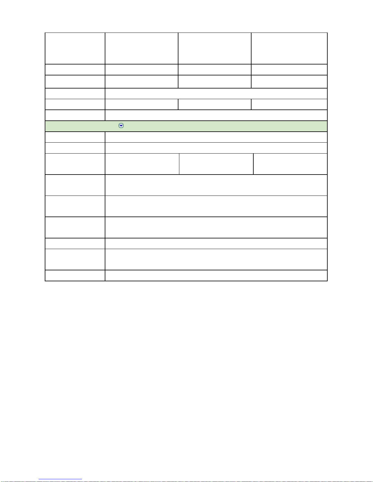
1.3 System Specifications
Panel
Model
LPC-1705
LPC-1707
LPC-17A4
LCD size
17”, 4:3
Display type
SXGA TFT
Resolution
1280 x 1024
Pixel Pitch
0.264mm (H) x 0.264mm (V)
Luminance
350cd/m2
Contrast ratio
800
Viewing angle
80 (U), 80 (D), 85 (L), 85 (R)
Response time
30 ms
Backlight
LED
Touch screen
5-wire Resistive
Light transmission
80%
Touch interface
USB
System
Board
EBM-PNV
EBM-CDV
EBM-A50M
CPU
Onboard Intel® Atom™
D525 Dual Core 1.8GHz
CPU
Onboard Intel® Atom™
D2550 1.86GHz CPU
Onboard AMD eOntario
T40E 1.0GHz CPU
System Chipset
Intel® ICH8-M
Intel® NM10 Chipset
AMD A50M Chipset
I/O Chip
Nuvoton W83627DHG-P
E/C IT8518E
Nuvoton W83627DHG-P
System Memory
Onboard 1GB SDRAM and
One 204-pin SODIMM
Supports Up to 3GB DDR3
800MHz SDRAM
One 204-pin SODIMM
Supports Up to 4GB DDR3
1066MHz SDRAM
Onboard 2GB 1066MHz
DDR3 and One 204-pin
SODIMM Supports Up to
4GB DDR3 1066MHz
SSD
One CF Socket by IDE
Secondary Slave Channel
Supports Type I/II Compact
Flash Card
One CF Socket by IDE
Secondary Slave Channel
Supports Type I/II Compact
Flash Card
One CF Socket by IDE
Secondary Slave Channel
Supports Type I/II Compact
Flash Card
Hard Driver Bay
One 2.5” SATA HDD
One 2.5” SATA HDD
One 2.5” SATA HDD
Watchdog Timer
Reset: 1sec. ~ 255min. and
1sec. or 1min./step
Reset: 1sec. ~ 255min. and
1sec. or 1min./step
Reset: 1sec. ~ 255min. and
1sec. or 1min./step
H/W Status Monitor
Monitoring System
Temperature, Voltage, and
Cooling Fan Status with
Auto Throttling Control
Monitoring System
Temperature, Voltage, and
Cooling Fan Status with
Auto Throttling Control
Monitoring System
Temperature, Voltage, and
Cooling Fan Status with Auto
Throttling Control
Expansion
2 x Mini PCIe Slot
1 x Mini PCIe Slot, Optional
Supports mSATA
2 x Mini PCIe Slot, Optional
Supports mSATA
Rear Panel I/O
Serial Port
1xRS-232/422/485 (default RS-232, RS-422/485 setting by jumper) Optional 2nd COM
Ethernet
1 x RJ-45 (Intel® 82574L
1 x RJ-45 (Intel® 82574L
2 x RJ-45 (Dual Realtek
Quick Reference Guide
LPC-17 Series Quick Reference Guide
7
Gigabit Ethernet,
Optional Dual 82574L
Gigabit Ethernet)
Gigabit Ethernet,
Optional Dual 82574L
Gigabit Ethernet)
RTL8111E Gigabit Ethernet)
VGA
1 x DB-15
1 x HDMI
1 x HDMI
Audio
Line-out (Realtek ALC888
Supports 5.1-CH Audio)
Line-out (Realtek ALC892
Supports 5.1-CH Audio)
Line-out (Realtek ALC892
Supports 5.1-CH Audio)
USB
2 x USB 2.0 (Optional Extra 2 x USB)
Mouse & K/B
1 x PS/2 KB & MS
1 x PS/2 KB & MS
N/A
Speaker
2 x 1W Speaker
Environment & Mechanical
Color
Front Silver & Rear Panel Black
Mounting
Wall/ Stand/ VESA 75mm x 75mm and 100mm x 100mm
System Power
Requirement
+12 ~ +26V DC Power Input
+12 ~ +26V DC Power Input
+12 ~ +26V DC Power Input
Power Adapter
Input: 100 ~ 250VAC/ 47 ~ 63Hz
Output: 60W Adapter (12V @ 5A Adapter)
Operating
Temperature
0°C ~ 40°C (32°F ~ 104°F)
Storage
Temperature
-10°C ~ 60°C (14°F ~ 140°F)
Relative Humidity
5% ~ 90% Relative Humidity, Non-condensing
Dimensions (W x D x
H)
382mm x 320mm x 58.8mm
Weight
5.2Kgs

LPC-17 Series
8 LPC-17 Series Quick Reference Guide
1.4 System Overview
1.4.1 Front View
1.4.2 Rear View
LPC-1705
LPC-1707/LPC-17A4
POWER
POWER

Quick Reference Guide
LPC-17 Series Quick Reference Guide
9
Connectors
Label
Function
Note
POWER
Power on button
Compact
Flash/COM2
CF Type I/II Socket with Ejector
Optional for 2nd COM port
COM1
Serial port 1 connector
DB-9 male connector
LINE OUT
Line-out audio jack
USB
2 x USB 2.0 connector
Dock USB
LAN1
RJ-45 Ethernet connector 1
KB/MS
(LAN2)
LPC-1705/1707 -- PS/2 connector
LPC-17A4 -- LAN2
HDD
HDD indicator
PWR
System power indicator
VGA/HDMI
CRT connector/HDMI connector
RESET
Reset button
DC-IN
DC Power-in connector

LPC-17 Series
10 LPC-17 Series Quick Reference Guide
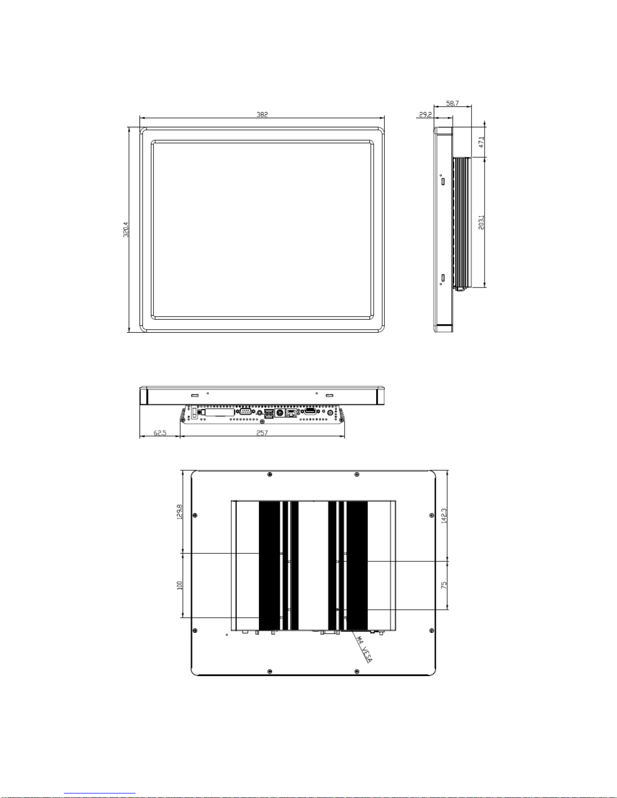
1.5 System Dimensions
1.5.1 LPC-1705 Front and Rear side
(Unit: mm)

Quick Reference Guide
LPC-17 Series Quick Reference Guide
11
1.5.2 LPC-1707 Front and Rear side
(Unit: mm)
LPC-17 Series
12 LPC-17 Series Quick Reference Guide
1.5.3 LPC-17A4 Front and Rear side
(Unit: mm)
Quick Reference Guide
LPC-17 Series Quick Reference Guide
13
2. Hardware
Configuration
Note: If you need more information, please visit our website:
http://www.avalue.com.tw

LPC-17 Series
14 LPC-17 Series Quick Reference Guide
2.1 LPC 17 Series connector mapping
2.1.1 Serial Port 1 connector (COM1)
In RS-232 Mode
Signal
PIN
PIN
Signal
DCD1
1 2 RxD1
TxD1
3 4 DTR1
GND
5 6 DSR1
RTS1
7 8 CTS1
RI1
9 NC
In RS-422 Mode
Signal
PIN
PIN
Signal
TxD1-
1 2 RxD1+
TxD1+
3 4 RxD1-
GND
5 6 NC
NC
7 8 NC
NC
9 NC
In RS-485 Mode
Signal
PIN
PIN
Signal
DATA1-
1 2 NC
DATA1+
3 4 NC
GND
5 6 NC
NC
7 8 NC
NC
9 NC
-
Quick Reference Guide
LPC-17 Series Quick Reference Guide
15
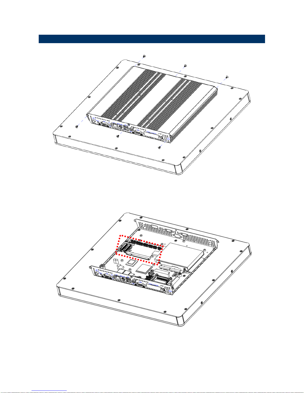
2.2 Installing Hard Disk & Memory
Step 1. Unfasten 6 screws from the case. Then take off the top chassis.
Step 2. Insert the SODIMM into the memory socket.

LPC-17 Series
16 LPC-17 Series Quick Reference Guide
Step 3. Insert the HDD into the Drive Bay. Remember to place the HDD down to the bottom
exactly in order to screw the device tightly.
HDD
 Loading...