


Part No. E20171205A1R
LPC 10”/12” Series
10.4”/12.1” Multifunctional Touch Panel PC
Quick Reference Guide
2nd Ed – 20 November 2013
Copyright Notice
Copyright 2013 Avalue Technology Inc., ALL RIGHTS RESERVED.

LPC 10”/12” Series
2 LPC 10”/12” Series Quick Reference Guide
1. Getting Started
1.1 Safety Precautions
Warning!
Always completely disconnect the power cord from your
chassis whenever you work with the hardware. Do not
make connections while the power is on. Sensitive
electronic components can be damaged by sudden power
surges. Only experienced electronics personnel should
open the PC chassis.
Caution!
Always ground yourself to remove any static charge before
touching the CPU card. Modern electronic devices are very
sensitive to static electric charges. As a safety precaution,
use a grounding wrist strap at all times. Place all electronic
components in a static-dissipative surface or static-shielded
bag when they are not in the chassis.
Risk of explosion if battery is replaced by an incorrect type.
Dispose of used batteries according to the instructions.
1.2 Packing List
1 x LPC 10"/12" Series Panel PC
1 x Quick Reference Guide
1 x DVD-ROM contains the followings:
— User’s Manual (this manual in PDF file)
— Ethernet driver and utilities
— VGA drivers and utilities
— Audio drivers and utilities
— WiFi drivers and utilities
— Touch controller drivers and utilities
1 x Power Adapter
1 x Stand for Panel PC (optional)

Quick Reference Guide
LPC 10”/12” Series Quick Reference Guide
3
1.3 System Specifications
Panel
Model
LPC-1205
LPC-1005
LCD size
12.1”, 4:3
10.4”, 4:3
Display type
SVGA
XGA
SVGA
XGA
Resolution
800 x 600
1024 x 768
800 x 600
1024 x 768
Color
262K
262K
262K
16.2M
Pixel pitch
0.240mm(H) x
0.240mm(V)
0.240mm(H) x
0.240mm(V)
0.264mm(H) x
0.264mm(V)
0.0685mm(H) x
0.2055mm(V)
Luminance
600 cd/m²
600 cd/m²
300 cd/m²
500 cd/m²
Contrast ratio
700
700
500
1200
Viewing angle
70(U), 70(D),
80(L), 80(R)
70(U), 70(D),
80(L), 80(R)
45(U), 65(D),
65(L), 65(R)
88(U), 88(D),
88(L), 88(R)
Response time
16 ms
16 ms
25 ms
25 ms
Backlight
LED
LED
LED
LED
Touch type
5 Wires resistive
5 Wires resistive
Touch interface
USB
USB
System
Board
EBM-PNV
CPU
Onboard Intel® Pineview D525 1.8GHz CPU
BIOS
AMI 8Mbit Flash BIOS
System Chipset
Intel ICH8-M
I/O Chipset
Winbond W83627DHG
System Memory
Onboard 1GB SDRAM and one SODIMM supports up to 3GB
SSD
One CF socket supports Type I / II Compact Flash Card.
HDD
Optional 2.5” SATA HDD
WiFi
Optional USB WiFi 802.11b/g
Watchdog Timer
Reset: 1 ~ 65535 sec./min. and 1 min./step
Audio
Realtek ALC888 supports 5.1-CH Audio
Ethernet
Intel® 82574L Gigabit LAN, Optional Dual LAN

LPC 10”/12” Series
4 LPC 10”/12” Series Quick Reference Guide
External I/O Ports
COM Port
1 x RS-232
Ethernet Port
1 x RJ-45
VGA / LCD Port
1 x DB-15
USB Port
2 x USB 2.0
Audio Port
Line-out
Mouse & K/B
1 x PS/2 KB & MS
Power Supply Unit
Power Requirement
+12V ~ +26V
Power Output
12V/5A (60W)
Environment & Mechanical
Operating Temperature
-10~40°C (14~104°F)
Storage Temperature
-20 to +75°C (-4~167°F)
Relative Humidity
5 to 90% @ 40°C (104°F), relative humidity, non-condensing
Dimension (W x D x H)
283 x 222x 45 mm
259 x 196 x 41mm
Weight
2.84 Kgs
2.11 Kgs
Mounting
Desktop (VESA Compliance)

Quick Reference Guide
LPC 10”/12” Series Quick Reference Guide
5
Panel
Model
LPC-1203
LPC-1003
LCD size
12.1”, 4:3
10.4”, 4:3
Display type
SVGA
XGA
SVGA
XGA
Resolution
800 x 600
1024 x 768
800 x 600
1024 x 768
Color
262K
262K
262K
262K
Pixel pitch
0.3075mm(H) x
0.3075mm(V)
0.240mm(H) x
0.240mm(V)
0.264mm(H) x
0.264mm(V)
0.20625mm(H) x
0.20625mm(V)
Luminance
450 cd/m²
450 cd/m²
230 cd/m²
300 cd/m²
Contrast ratio
1000
700
500
500
Viewing angle
89(U), 89(D),
89(L), 89(R)
80(U), 80(D),
80(L), 80(R)
55(U), 65(D),
70(L), 70(R)
60(U), 60(D),
70(L), 70(R)
Response time
25 ms
25 ms
25 ms
25 ms
Backlight
CCFL
CCFL
CCFL
CCFL
Touch type
5 Wires resistive
5 Wires resistive
Touch interface
USB
USB
System
Board
EBM-945GSE
CPU
Onboard Intel Atom N270 1.6GHz (2.5W)
BIOS
Award 4 Mbit Flash BIOS
System Chipset
Intel 945GSE + ICH7-M
I/O Chipset
ITE 8712F
System Memory
Onboard 1GB DDR2, extra one SODIMM supports up to 2GB 400/533 SDRAM
SSD
One CF socket supports Type I / II Compact Flash Card.
HDD
Optional 2.5” SATA HDD or 44-pin enhanced IDE HDD
WiFi
Optional USB WiFi 802.11b/g
Watchdog Timer
Reset: 1 ~ 65535 sec./min. and 1 min./step
Display
Intel 945GSE GMCH integrated GMA950 graphics
Audio
Realtek ALC 655 supports 5.1-CH Audio
Ethernet
Dual Realtek RTL8111C Gigabit LAN, supports wake on LAN

LPC 10”/12” Series
6 LPC 10”/12” Series Quick Reference Guide
External I/O Ports
COM Port
1 x RS-232/422/485 setting by BIOS*, optional extra 1 x RS-232/422/485
Ethernet Port
Dual RTL8111C Giga LAN
VGA / LCD Port
1 x DB-15
Audio Port
Line-out
USB Port
2 x USB 2.0
Power Supply Unit
Power Requirement
+12V ~ +26V
Power Output
12V/5A (60W)
Environment & Mechanical
Operating Temperature
0~60°C (32~140°F)
0~40°C (32~104°F)
Storage Temperature
-20 to +75°C (-4~167°F)
-20 to +75°C (-4~167°F)
Relative Humidity
5 to 90% @ 40°C (104°F), relative humidity, non-condensing
Dimension (W x D x H)
283 x 222x 45 mm
259 x 196 x 41mm
Weight
2.84 Kgs
2.11 Kgs
Mounting
Desktop (VESA Compliance)

Quick Reference Guide
LPC 10”/12” Series Quick Reference Guide
7
Panel
Model
LPC-1201
LPC-1001
LCD size
12.1”, 4:3
10.4”, 4:3
Display type
SVGA
XGA
SVGA
XGA
Resolution
800 x 600
1024 x 768
800 x 600
1024 x 768
Color
262K
262K
262K
262K
Pixel pitch
0.3075mm(H) x
0.3075mm(V)
0.240mm(H) x
0.240mm(V)
0.264mm(H) x
0.264mm(V)
0.20625mm(H) x
0.20625mm(V)
Luminance
450 cd/m²
450 cd/m²
230 cd/m²
300 cd/m²
Contrast ratio
1000
700
500
500
Viewing angle
89(U), 89(D),
89(L), 89(R)
80(U), 80(D),
80(L), 80(R)
55(U), 65(D),
70(L), 70(R)
60(U), 60(D),
70(L), 70(R)
Response time
25 ms
25 ms
25 ms
25 ms
Backlight
CCFL
CCFL
CCFL
CCFL
Touch type
5 Wires resistive
5 Wires resistive
4 Wires resistive
5 Wires resistive
Touch interface
USB
USB
System
Board
EBM-CX700
CPU
Onboard VIA Eden ULV 1GHz (3.5W), up to 1.6GHz (8W) CPU
BIOS
Award, 512KB Flash BIOS
System Chipset
VIA CX700M
I/O Chipset
VIA VT1211
System Memory
One 200-pin DDR2 SODIMM socket, supports up to 1GB DDR2 400/533 SDRAM
SSD
One CF socket supports Type I / II Compact Flash Card.
HDD
Optional 2.5” SATA HDD or 44-pin enhanced IDE HDD
WiFi
Optional USB WiFi 802.11b/g
Watchdog Timer
Reset: 1 ~ 65535 sec./min. and 1 min./step
Display
VIA CX700M
Audio
VIA VT1708A supports 2CH Audio
Ethernet
Dual RTL8110SC Gigabit LAN/10/100/1000 Base-Tx Fast Ethernet compatible

LPC 10”/12” Series
8 LPC 10”/12” Series Quick Reference Guide
External I/O Ports
COM Port
1 x RS-232
Ethernet Port
Dual RTL8110SC Giga LAN
VGA / LCD Port
1 x DB-15
Audio Port
Line-out
USB Port
2 x USB 2.0
Power Supply Unit
Power Input
12V
Power Output
12V/5A (60W)
Environment & Mechanical
Operating Temperature
-10~60°C (14~140°F)
0~40°C (32~104°F)
Storage Temperature
-20 to +75°C (-4~167°F)
-20 to +75°C (-4~167°F)
Relative Humidity
5 to 90% @ 40°C (104°F), relative humidity, non-condensing
Dimension (W x D x H)
283 x 222x 45 mm
259 x 196 x 41mm
Weight
2.84 Kgs
2.11 Kgs
Mounting
Desktop (VESA Compliance)

Quick Reference Guide
LPC 10”/12” Series Quick Reference Guide
9
1.4 System Overview
1.4.1 Front View
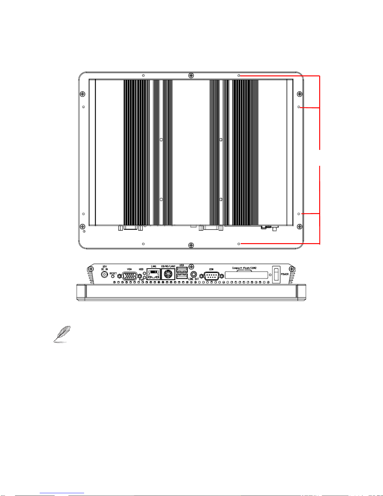
1.4.2 Rear View
Connectors
Label
Function
Note
POWER
Power on button
CF
CF Type I/II Socket with Ejector
Optional for 2nd COM port
COM
Serial port
DB-9 male connector
LINE OUT
Line-out audio jack
USB
2 x USB 2.0 connector
Dock USB
LAN1
RJ-45 Ethernet connector 1
KB/MS
(LAN2)
LPC-1005/1205 -- PS/2 connector
LPC-1001/1003/1201/1203 -- LAN2
HDD
HDD indicator
PWR
System power indicator
VGA
CRT connector
DB-15 female connector
RESET
Reset button
DC-IN
DC Power-in connector
POWER

LPC 10”/12” Series
10 LPC 10”/12” Series Quick Reference Guide
1.5 System Dimensions
1.5.1 LPC-12 Front and Rear side

Quick Reference Guide
LPC 10”/12” Series Quick Reference Guide
11
1.5.2 LPC-10 Front and Rear side
(Unit: mm)
LPC 10”/12” Series
12 LPC 10”/12” Series Quick Reference Guide
1.5.3 Bottom and Rear Side
Note: The M3*3 screw holes are reserved for LPC Series Panel Mount Brackets. Improper usage
may harm the mechanical parts.
M3*3

Quick Reference Guide
LPC 10”/12” Series Quick Reference Guide
13
Follow these steps to install the wall mounting arm:
1. Place the wall mounting arm onto the back of panel PC.
2. Insert the 4 screws into the holes and tighten. Line up the holes of the arm with the holes of panel PC.
3. Reconnect the cables. Refer to the user’s manual of the optional wall mounting arm to attach it to the wall.
Note: 75mmx75mm VESA hole(n=4), M4, pitch=0.5mm, deep=4mm. Due to safety concerns, if
the VESA mounting kit is purchased separately, please make sure the mounting kit is
UL-Listed.
M4*4

LPC 10”/12” Series
14 LPC 10”/12” Series Quick Reference Guide
2. Hardware
Configuration
Note: If you need more information, please visit our website:
http://www.avalue.com.tw

Quick Reference Guide
LPC 10”/12” Series Quick Reference Guide
15
2.1 BIOS settings
2.1.1 RS232/422/485 setting using BIOS
2.1.1.1 EBM-945GSE M/B
The COM port setting of LPC-1003/1203, which applies for EBM-945GSE M/B, can be
configured by BIOS. The path is shown as below.
[BIOS Menu] [Integrated Peripherals] [Super IO Device]
[COMPORT 232/422/485]
The panel backlight of LPC-1003/1203, which applies for EBM-945GSE M/B, can be
configured by BIOS as well. The path is shown as below.
[BIOS Menu] [Advanced Chipset Features] [LVDS Back Light]
To know more about other settings, please refer to EBM-945GSE Quick Installation Guide
or User’s Manual.

LPC 10”/12” Series
16 LPC 10”/12” Series Quick Reference Guide
2.1.1.2 EBM-PNV M/B
The COM port setting of LPC-1005/1205, which applies for EBM-PNV M/B, can be
configured by BIOS. The path is shown as below.
[BIOS Menu] [Advanced] [Super IO Configuration]
[Serial Port 2 mode for RS-232/422/485]
Note: To change COM port setting, it is necessary to adjust SW2, JP1,
JP2 settings of EBM-PNV as well.

Quick Reference Guide
LPC 10”/12” Series Quick Reference Guide
17
2.1.1.2.1 EBM-PNV board COM port setting
i Serial port 1/ 2 RS-232/ 422/ 485 mode select (JP1/ JP2)
ii Serial port 1/ 2 - RS-232/ 422/ 485 mode select (SW2)

LPC 10”/12” Series
18 LPC 10”/12” Series Quick Reference Guide
2.1.2 PWM Backlight control setting for EBM-PNV
The Backlight control setting which applies for EBM-PNV M/B can be configured by BIOS;
the path is shown as below.
[Chipset] [North Bridge Configuration] [Video Function Configuration]
Panel 2 Back light mode: PWM mode
Panel 2 Back light control: 100%
Note:
Panel 1 Back light mode : DC mode
Panel 1 Back light control : 50%
Panel 1 control for 18bit LVDS panel.
To know more about other settings, please refer to EBM-PNV Quick Installation Guide or
User’s Manual.

Quick Reference Guide
LPC 10”/12” Series Quick Reference Guide
19
2.2 Installing Hard Disk & Memory
Step 1. Unfasten 6 screws from the case. Then take off the top chassis.
Step 2. Insert the SODIMM into the memory socket.
LPC 10”/12” Series
20 LPC 10”/12” Series Quick Reference Guide
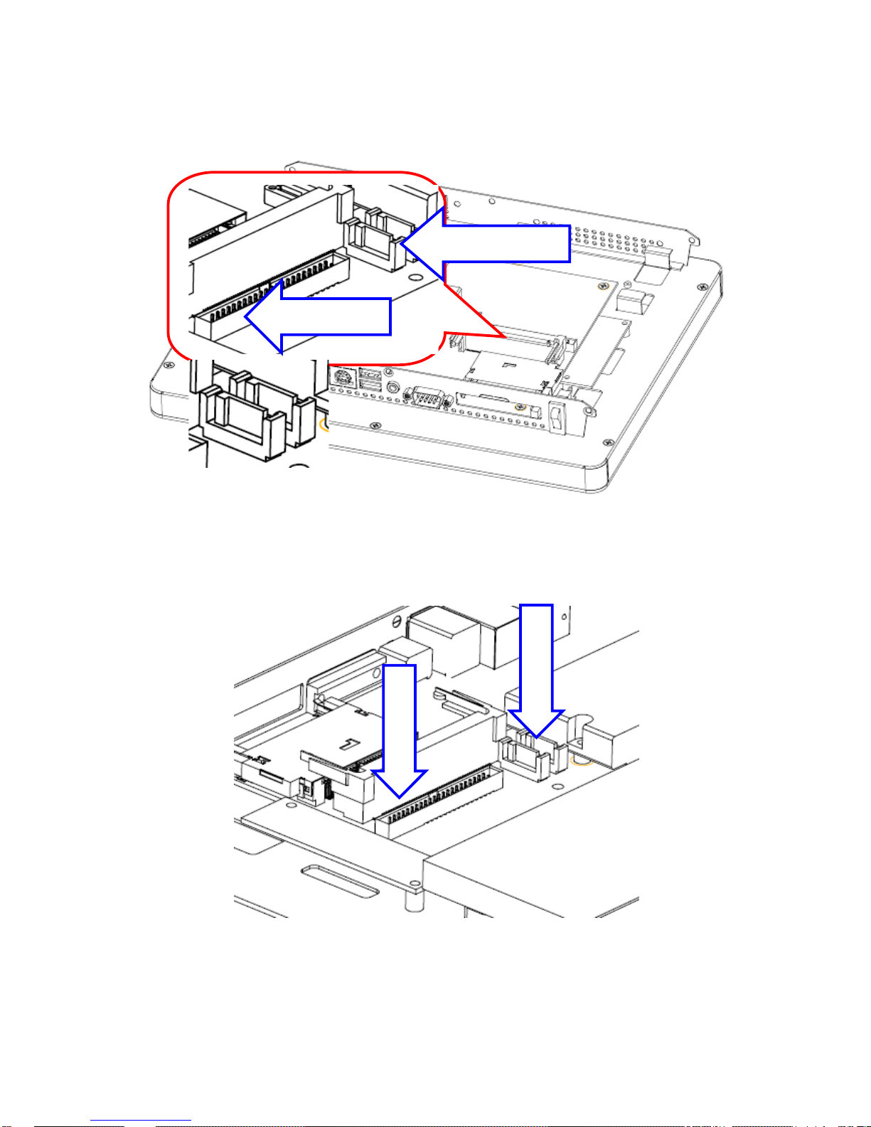
Step 3-1. HDD Installation: Insert the cable to connect the HDD and the SATA connecter.
Step 3-2. SATA HDD Installation: By default, the SATA cables had been inserted to the
according connectors. Just connect to SATA HDD with the two cables.
IDE Connector
SATA Connector
SATA wire
SATA cable

Quick Reference Guide
LPC 10”/12” Series Quick Reference Guide
21
Step 3-3. Insert the HDD into the Drive Bay. Remember to place the HDD down to the
bottom exactly in order to screw the device tightly.
Step 4. Place back the chassis with 6 screws locked.
HDD
 Loading...