


CCD-07W01 /
CCD-10W01 series
Panel PC
USER Manual
2
nd
Ed –17 October 2017
Copyright Notice
Copyright 2016 ALL RIGHTS RESERVED.

ii
Copyright
© 2016 All rights reserved. All information in this manual is subject to change without notice. No
part of this manual may be reproduced or transmitted, in any form or by any means, without the
written permission.

iii
Declaration of Conformity
CE Conformity Statement
Radio products with the CE alert marking comply with the R&TTE Directive (1999/5/EC) issued by the
Commission of the European Community. Compliance with this directive implies conformity to the
following European Norms (in brackets are the equivalent international standards)
EN 60950-1 (IEC60950-1) - Product Safety
Products that contain the radio transmitter are labeled with CE alert marking and may also carry the
CE logo.
FCC Compliance Statement
This device complies with part 15 of the FCC Rules. Operation is subject to the following two
conditions:
1. The device may not cause harmful interference;
2. The device must accept any interference received, including interference that may cause
undesired operation.
CAUTION!
The radiated output of this device is far below the FCC radio frequency exposure
limits. Nevertheless, the device shall be used in such a manner that the potential for
human contact during normal operation is minimized. When connecting an external
antenna to the device, the antenna shall be placed in such a manner to minimize the
potential for human contact during normal operation. In order to avoid the
possibility of exceeding the FCC radio frequency exposure limits, human proximity to
the antenna shall not be less than 20 cm (8 inches) during normal operation.
This equipment has been tested and found to comply with the limits for a Class B digital device,
pursuant to part 15 of the FCC Rules. These limits are designed to provide reasonable protection
against harmful interference in a residential installation. This equipment generates uses and can
radiate radio frequency energy. If this equipment does cause harmful interference to radio or
television reception, which can be determined by turning the equipment off and on, the user is
encouraged to try and correct the interference by one or more of the following measures.
However, there is no guarantee that interference will not occur in a particular installation. If this
equipment does cause harmful interference to radio or television reception, which can be determined
by turning the equipment off and on, the user is encouraged to try to correct the interference by one
or more of the following measures:
Reorient or relocate the receiving antenna

iv
Increase the separation between the equipment and receiver
Connect the equipment into an outlet on a circuit different from that to which the receiver is
connected
Consult the dealer or an experienced computer technician for help
Technical Support and Assistance
1. Contact your distributor or sales representative for technical support if you need
additional assistance. Please have the following information ready before you call:
Product name and serial number
Description of your peripherals attachments
Description of your software (OS, version, application software, etc.)
A complete description of your problems
The exact wording or any error messages
Safety Instruction
Use the following safety guideline to help protect yourself and CCD.
Do not attempt to service the CCD yourself. Always follow installation instructions closely.
Be sure that nothing rests on the AC adapter's power cable and that the cable is not located
where it can be tripped over or stepped on.
Do not cover the AC adaptor with papers or other items that will reduce cooling; also, do not
use the AC adapter while it is inside a carrying case. Use only the AC adapter, power cord, and
batteries that are approved for use with this CCD. Use of another type of battery or AC adapter
may cause risk of fire or explosion.
If you use an extension cable with the AC adapter, ensure that the total ampere rating of the
products plugged in to the extension cable does not exceed the ampere rating of the extension
cable.
When you move the CCD between environments with very different temperature and/or
humidity ranges, condensation may form on or within the CCD. To avoid damaging the CCD,
allow sufficient time for the moisture to evaporate before using the CCD.
When you disconnect a cable, pull on its connector or on its strain relief loop, not on the cable
itself. As you pull out the connector, keep it evenly aligned to avoid bending any connector pins.
Also, before you connect a cable make sure both connectors are correctly oriented and aligned.

v
Battery Safety
RTC Battery Caution
RISK OF EXPLOSION IF BATTERY IS REPLACED BY AN INCORRECT TYPE. DISPOSE OF USED BATTERIES
ACCORDING TO THE INSTRUCTIONS.
Do not place the battery incorrectly as this may cause danger of explosion.
Dispose of used batteries according to the manufacturer's instructions.
Do not dispose of batteries in a fire. They may explode. Check with local authorities for disposal
instructions.
CAUTION!
The battery used in this device may present a risk of fire or chemical burn if
mistreated. Do not disassemble, heat above 50°C, or incinerate. Replace the battery
with certified CR2032 only. Use of another battery may present a risk of fire or
explosion.
Dispose of used batteries according to local disposal regulations. Keep away from
children. Do not disassemble and do not dispose of in a fire.

vi
Contents
CHAPTER 1 ...................................................................................... - 2 -
Understanding Your CCD ................................................................ - 2 -
1.1 Product Features ..................................................................................................... - 3 -
1.2 Technical Specification ............................................................................................ - 3 -
1.3 Checking the Delivery Package................................................................................ - 4 -
1.3.1 Procedure ....................................................................................................... - 4 -
1.3.2 Packing Contents ........................................................................................... - 4 -
1.4 Optional Accessories ............................................................................................... - 5 -
1.5 Exploring CCD.......................................................................................................... - 5 -
1.5.1 Dimension ....................................................................................................... - 5 -
1.5.2 Front View ..................................................................................................... - 6 -
1.5.3 Rear View ....................................................................................................... - 7 -
1.6 Ordering Information ............................................................................................... - 8 -
CHAPTER 2 ...................................................................................... - 9 -
Hardware Functionality ................................................................... - 9 -
2.1 Power Connector .................................................................................................. - 10 -
2.2 HDMI 1.4a Display Port ......................................................................................... - 10 -
2.3 USB 2.0 Port .......................................................................................................... - 11 -
2.5 Ethernet: LAN Port ................................................................................................ - 12 -
2.6 Audio Port ............................................................................................................. - 13 -
CHAPTER 3 .................................................................................... - 15 -
Wireless Connections ...................................................................... - 15 -
3.1 Wi-Fi Connection................................................................................................... - 16 -
3.2 Bluetooth Connection ........................................................................................... - 18 -
CHAPTER 4 .................................................................................... - 20 -

vii
BIOS Setup (SCU) .......................................................................... - 20 -
4.1 Overview ............................................................................................................... - 21 -
4.1.1 Basic Knowledge Required ...........................................................................- 21 -
4.2 Entering the BIOS Selection Menu ......................................................................... - 21 -
4.2.1 Procedure ......................................................................................................- 21 -
4.3 BIOS Setup (SCU) ................................................................................................... - 21 -
4.3.1 Structure of the BIOS Setup Menu ..............................................................- 21 -
4.3.2 Navigation and Options Selection .................................................................- 22 -
4.3.3 Main Menu ....................................................................................................- 23 -
4.3.4 Security Menu ...............................................................................................- 24 -
4.3.5 Boot Menu .....................................................................................................- 26 -
4.3.6 Exit Menu ......................................................................................................- 28 -
Appendix A...................................................................................... - 31 -
Mounting Kits Installation ............................................................. - 31 -
A.1 VESA Mounting Installation .................................................................................. - 32 -
Appendix B ...................................................................................... - 33 -
Pin Assignments .............................................................................. - 33 -
B.1 HDMI Connector .................................................................................................... - 34 -
B.2 USB 2.0 Type A Connector ..................................................................................... - 34 -
B.3 LAN Port (RJ-45) .................................................................................................... - 35 -

- 2 -
CHAPTER 1
Understanding Your CCD
Thank you for choosing the CCD series product. We will start here to introduce the basics
of CCD. Information described in this chapter includes: features, specification, packing list,
I/O ports and appearance giving you an overall picture about your embedded panel PC.

- 3 -
1.1 Product Features
▪ Cross-platform capability to satisfy versatile application needs
▪ Streamline, modern design with IPS panel and projected capacitive multi-touch screen, giving
excellent user experiences
▪ Ease integration and configuration effort with rich I/O and wireless communication technology
▪ Scratch resistance, no moving parts, maintenance free
▪ Standard VESA mount support, simplifying the field installation
1.2 Technical Specification
Specification 7” 10.1”
Display Resolution 1024 x 600 1280 x 800
Luminance 300 nits 350 nits
Type TFT LED-backlit TN LCD TFT LED-backlit IPS LCD
Touch Type 10-point projected capacitive touch screen
System CPU & Chipset Intel® Atom™ Z3735G QC 1.33GHz Processor with Turbo Boost to 1.83GHz
Memory Onboard 2GB DDR3L 1600 MT/s (Z3735F)
Storage Onboard 32G eMMC
Power Input Voltage 12 – 24 VDC
Type AT mode
Battery 1 x RTC battery
I/O Power 1 x DC-in Jack
HDMI 1 x Standard HDMI 1.4a
USB 2 x USB 2.0
LAN 1 x RJ-45
Audio 1 x 3-pole 3.5mm Headphone Jack
Ethernet Speed 10/100
Communication Wi-Fi Built-in 802.11 b/g/n
Bluetooth Built-in Bluetooth 4.0
OS Support Windows Windows 10 IoT
Android Android 5.1
Linux Ubuntu 16.04 (kernel: V4.5)
Mechanical Construction Plastic
Dimension 191 x 124 x 30 mm 261 x 175 x 34 mm
Weight 580 g 800 g
Mounting VESA (75 x 75)
Environmental Temperature Operating Temperature: 0°C ~ +40 °C
Storage Temperature: -20°C ~ +60°C

- 4 -
Relative
Humidity
0 ~ 90%@40°C (non-condensing)
Vibration IEC 60068-2-64, random, 5Grms 5-500Hz, 1Oct./min, 1hr/axis
Shock IEC 60068-2-27, half sine, 50G, 11ms
Certification EMC CE/FCC Class B
Safety CB
1.3 Checking the Delivery Package
1.3.1 Procedure
1. When accepting a delivery, please check the packaging for visible transport damage.
2. If any transport damage is present at the time of delivery, lodge a complaint at the shipping
company in charge. Have the shipper confirm the transport damage.
3. Unpack the device at its installation location.
4. Keep the original packaging in case you have to transport the unit again.
NOTICE!
Damage to the device during transport and storage!
If a device is transported or stored without packaging, shocks, vibrations, pressure and
moisture may impact the unprotected unit. A damaged packaging indicates that ambient
conditions have already had a massive impact on the device.
The device may be damaged.
Do not dispose of the original packaging. Pack the device during transportation and
storage.
1.3.2 Packing Contents
Before setting up the system, please check the contents of the packaging and any accessories you may
have ordered for completeness and damage. If the contents of the packaging are incomplete,
damaged or do not match your order, inform the responsible delivery service or contact your dealer
immediately.
▪ CCD x 1
▪ 40W/19V Adaptor x 1
▪ 3-pin power cord

- 5 -
1.4 Optional Accessories
This chapter contains the scope of accessories valid at the time these operating instructions were
written.
▪ 60W/12V adapter with power cord
▪ 65W/19V adapter with power cord
1.5 Exploring CCD
1.5.1 Dimension
▲ Figure: 7” Panel PC Dimension
▲ Figure: 10.1” Panel PC Dimension
- 6 -
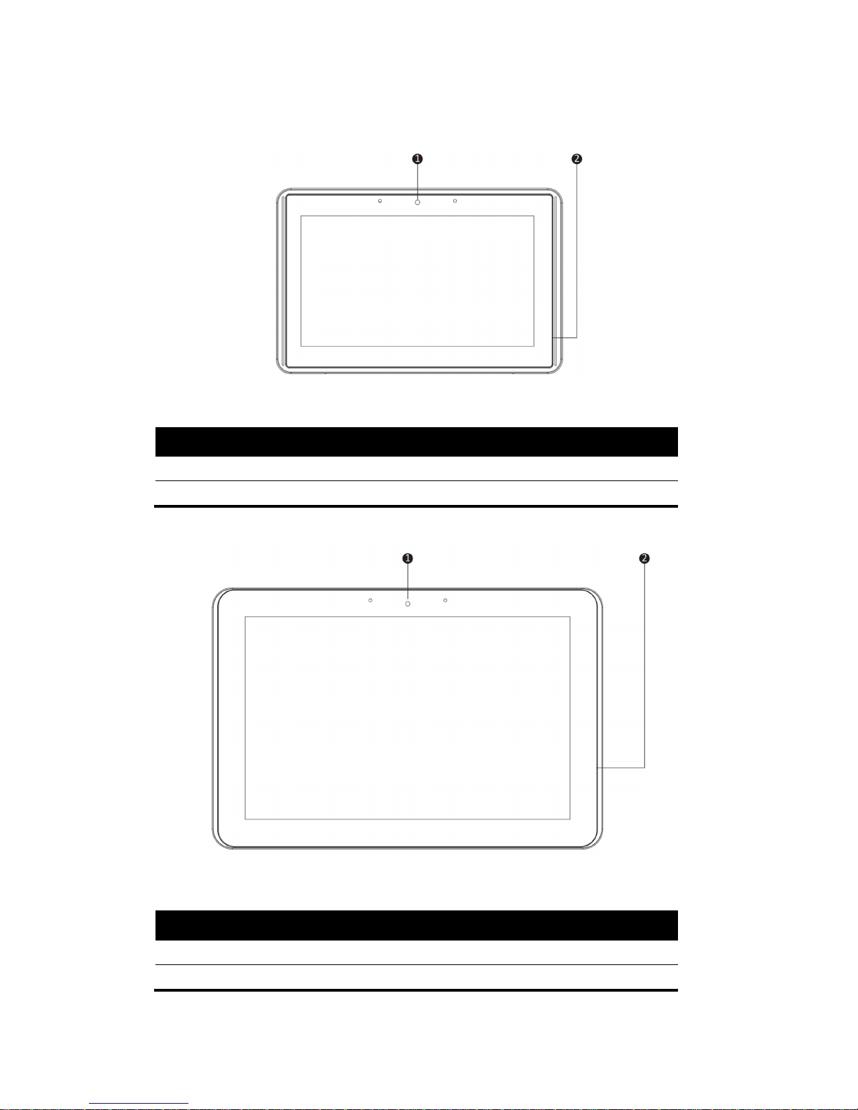
1.5.2 Front View
▲ Figure: 7” Panel PC Front View
No. Description
1 Camera
2 Microphone
▲ Figure: 10.1” Panel PC Front View
No. Description
1 Camera
2 Microphone
- 7 -
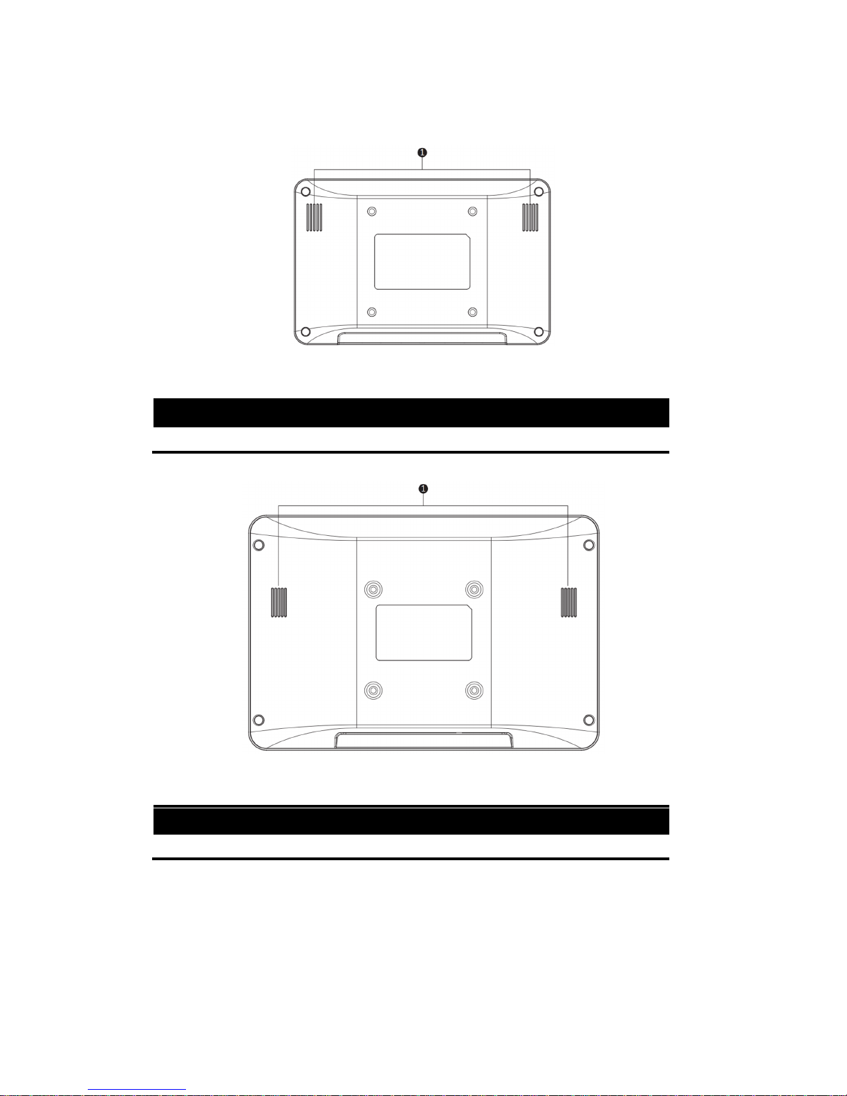
1.5.3 Rear View
▲ Figure: 7” Rear View
No. Description
1 Speaker
▲ Figure: 10.1” Rear View
No. Description
1 Speaker

- 8 -
1.6 Ordering Information
There are two SKUs – 7” and 10.1” in CCD series, as listed below:
Model P/N Description
CCD-07W01
Win10
CCD-07W01-7V38C-1R 7” Panel PC with Intel®Atom™ Z3735F, 2GB DRAM, 32GB
eMMC, Win10 IoT 2016
CCD-07W01
Linux
CCD-07W01-7V37C-1R 7” Panel PC with Intel®Atom™ Z3735F, 2GB DRAM, 32GB
eMMC, Linux Ubuntu 16.04
CCD-07W01
Android
CCD-07W01-7V39C-1R 7” Panel PC with Intel®Atom™ Z3735F, 2GB DRAM, 32GB
eMMC, Android 5.1
CCD-10W01
Win10
CCD-10W01-7V38C-1R 10.1” Panel PC with Intel®Atom™ Z3735F, 2GB DRAM, 32GB
eMMC, Win10 IoT 2016
CCD-10W01
Linux
CCD-10W01-7V37C-1R 10.1” Panel PC with Intel®Atom™ Z3735F, 2GB DRAM, 32GB
eMMC, Linux Ubuntu 16.04
CCD-10W01
Android
CCD-10W01-7V39C-1R 10.1” Panel PC with Intel®Atom™ Z3735F, 2GB DRAM, 32GB
eMMC, Android 5.1

- 9 -
CHAPTER 2
Hardware Functionality

- 10 -
2.1 Power Connector
CCD comes with a round-headed DC-in jack that carries 12 – 24 VDC external power supply. To
prevent damage to the CCD, always use the verified power adapter provided by us.
▲ Figure: DC-in Jack
▲ Figure: Connecting Adaptor via DC-in Jack
CAUTION!
The power adapter may become warm to hot when in use. Do not cover the adapter and
keep it away from your body.
2.2 HDMI 1.4a Display Port
The HDMI (High Definition Multimedia Interface) port supports a Full-HD device such as a LCD TV or a
monitor to allow viewing on a larger external display. You could refer to Appendix B.1 for pin
assignments.

- 11 -
▲ Figure: HDMI Connector
▲ Figure: Connecting display via HDMI
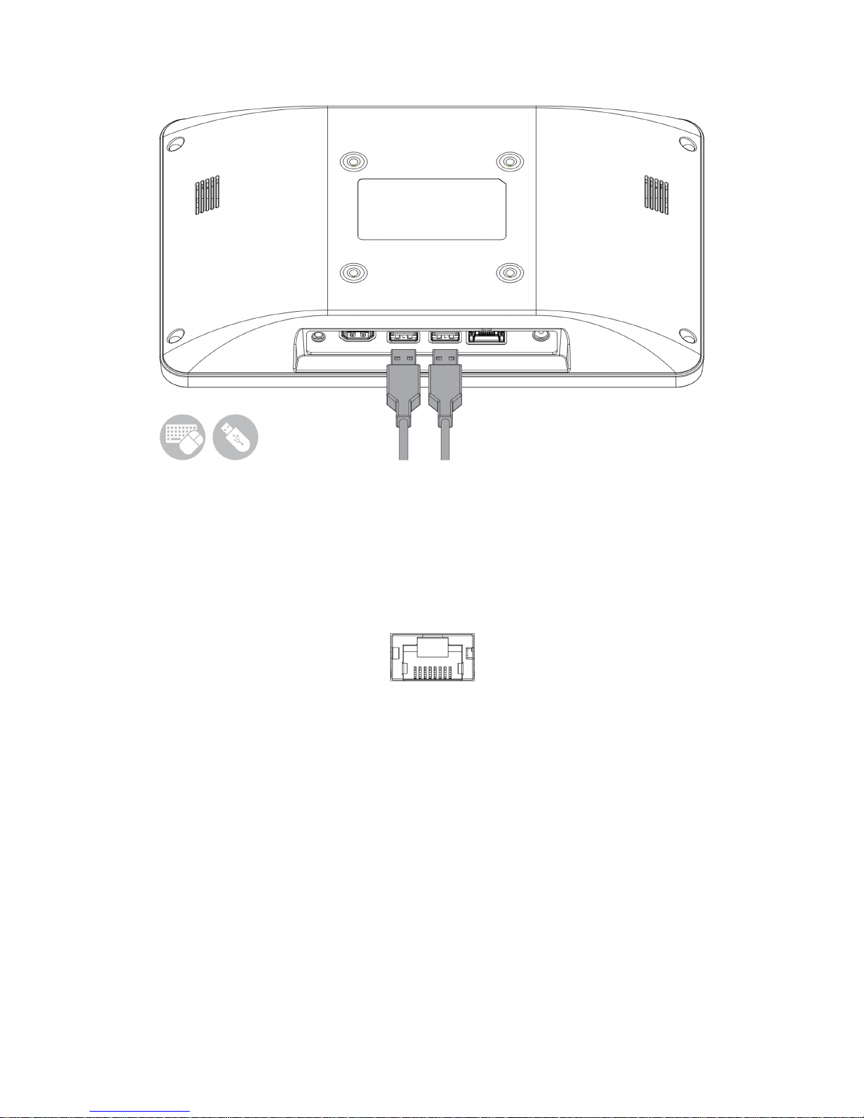
2.3 USB 2.0 Port
The USB (Universal Serial Bus) 2.0 ports are compatible with USB 1.1 devices such as keyboards,
mouse, cameras, and hard disk drives. USB allows many devices to run simultaneously on a single
computer with some peripherals acting as additional plug-in hubs.
▲ Figure: USB 2.0 Connector
- 12 -
▲ Figure: Connecting USB Device via USB 2.0 Port
2.5 Ethernet: LAN Port
The 8-pin RJ-45 LAN port equipped 10/100 controller which is fully IEEE 802.3 10BASE-T and 802.3u
100BASE-T compliant supports a standard Ethernet cable for connecting to a local network.
▲ Figure: 10/100 LAN Port

- 13 -
▲ Figure: Connecting network via LAN Port
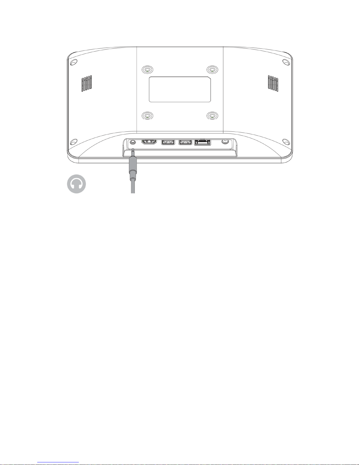
2.6 Audio Port
The supported interface with 3.5 mm audio jack in CCD is:
▪ Line-out
▲ Figure: Audio Jack
- 14 -
▲ Figure: Connecting Audio via Line Out

- 15 -
CHAPTER 3
Wireless Connections

- 16 -
3.1 Wi-Fi Connection
Connecting to a new Wi-fi network with Windows 10 is very easy. This may be helpful when setting up
a new device or if you're bringing your device to a new place. Follow these steps:
NOTICE!
Make sure you have installed and configured the wireless network (i.e. Hot Spot) correctly;
you'll notice the new wireless network icon in the system tray. To connect to your network,
click the network icon in the system tray and select from one of the available networks.
1. Click the Start menu > Settings
2. Click Network & Internet

- 17 -
3. Turn Wi-Fi button on
4. In the Wi-Fi section, you'll find all the wireless networks available to you, which is the same list
you see in the system tray. Select one of them and enter the Wi-Fi password if needed.

- 18 -
3.2 Bluetooth Connection
There are many different types of Bluetooth enabled devices you can add and pair to your CCD, such
as mobile phones, wireless headsets, and wireless mouse devices and keyboards. Here's how to find
Bluetooth settings:
1. Click the Start menu > Settings

- 19 -
2. Click Devices
3. In the Devices section, you can find all Bluetooth devices supported. If you don’t see Bluetooth
listed in Devices settings, it might have Bluetooth hardware that’s not recognized. Clicking on any
existing device gives you the option to set that device as default or remove that device.

- 20 -
CHAPTER 4
BIOS Setup (SCU)
The System Configuration Utility (SCU) is a program for configuring the BIOS
(Basic Input / Output System) settings your computer.
BIOS is a type of firmware used to perform hardware initialization during the
booting process on IBM PC compatible computers and to provide runtime
services for OS and programs. Your computer needs the BIOS settings to
recognize types of installed devices and establish special functions.
This chapter describes the operation of the SCU program.

- 21 -
4.1 Overview
The BIOS Setup program, or BIOS Setup for short, is located, together with the setup parameters, in a
FLASH block on the motherboard. Change the setup parameters of the device in the BIOS Setup, e.g.
system time or boot sequence.
Your device configuration is preset for operating with the included software. You should only change
the default setup parameters if technical modifications to your device require different parameters.
4.1.1 Basic Knowledge Required
A solid background in personal computers and Microsoft operating systems is required to understand
this chapter.
4.2 Entering the BIOS Selection Menu
4.2.1 Procedure
Step 1: Switch on or restart the device.
Step 2: Immediately press the “F2” button and keep it pressed after switching on the device.
4.3 BIOS Setup (SCU)
4.3.1 Structure of the BIOS Setup Menu
The individual setup parameters are distributed between different menus and submenus. Not all
menus are included in each supplied device configuration. The following table shows the menus.
Menu Meaning
Main Display system information, for example, BIOS version, processor and memory
Security Security functions, e.g., setting a password
Boot Determine boot options, e.g., boot order or USB boot
- 22 -
Exit Save and exit (see Exit menu)
The menus always have the same structure. The figure below shows an example for the "Main" menu.
Device-specific information is shown blocked.
4.3.2 Navigation and Options Selection
Information on the keyboard is located in the bottom of the screen. A brief use of the keyboard is
described:
Button Function
←, → Select a menu title
↑, ↓ Select a menu item or option
+, - Change the value
Enter 1) Shows the sub-menu, if it is available.
2) Opens or closes the option window when an item has been selected.
Esc 1) Return from a submenu to the previous menu.
2) Close an open window with options.
F9 Assign the values with the default settings.
F10 Save and exit the BIOS setup

- 23 -
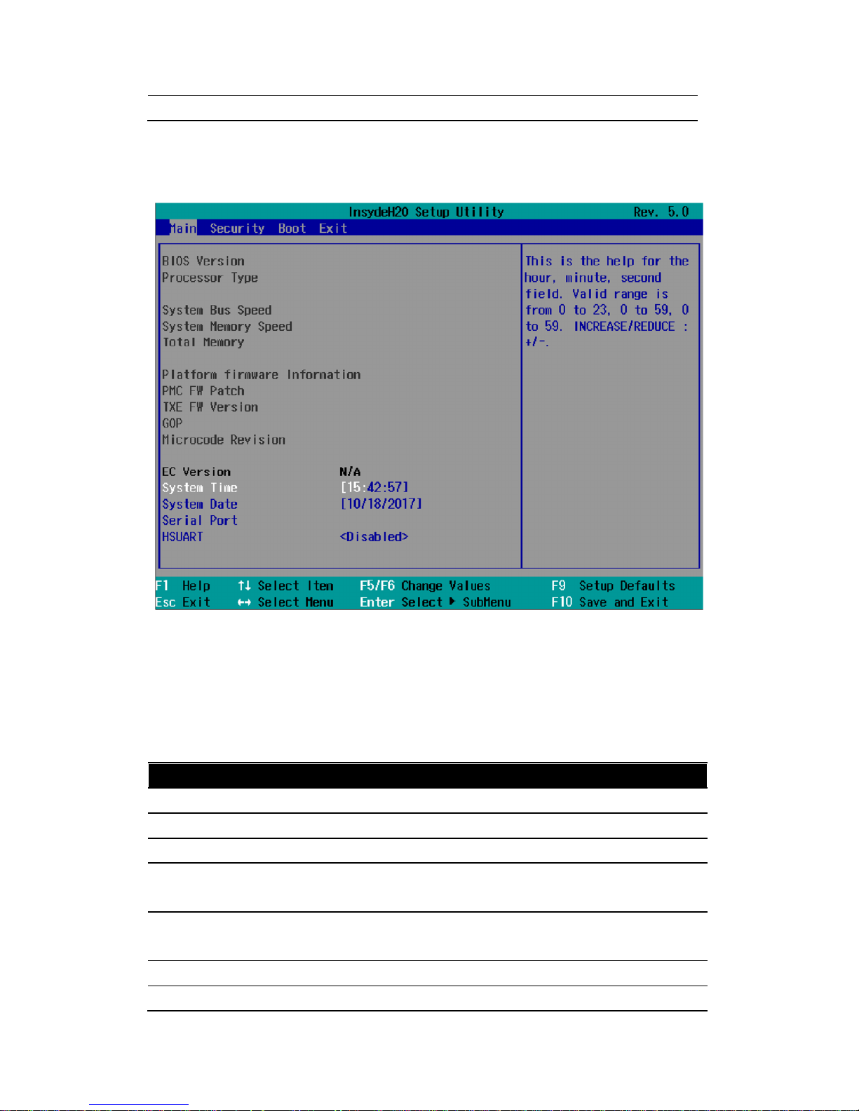
4.3.3 Main Menu
The "Main" menu shows the most important parameters that identify your device. You can set the
date and time. The following figure shows an example for the "Main" menu.
Parameter Option Meaning
BIOS Version NA Current software version of installed BIOS.
Processor Type NA Display the CPU model and speed.
System Bus Speed NA Display the auto-detected speed of the system.
System Memory Speed NA Display the auto-detected speed of the system memory.
Total Memory NA Display the total amount of detected system memory installed.
Platform firmware Information NA
PMC FW Patch NA
TXE FW Version NA
GOP NA
Microcode Revision NA
EC Version NA

- 24 -
System Time Adjust time Current time of the device. Format: "Hour/Minute/Second".
System Date Adjust date Current date of the device. "Month/Day/Year".
Serial Port NA
HSUART Enabled Enable the High Speed UART
Disabled Disable the High Speed UART
You can use the <Enter> key to move within a format, for example, from hour to minute. You can use
the [+] and [-] keys to set the desired values for the date and time.
4.3.4 Security Menu
The "Security" menu lets you block access to your device using passwords. The following figure shows
an example for the "Security" menu.

- 25 -
Parameter Option Meaning
Supervisor Password Not Installed The general password is set (Installed) or not set (Not Installed).
Enter Password
User Password Not Installed The user password is set (Installed) or not set (Not Installed).
Enter Password
Set Supervisor Password NA Set supervisor password for full access to the BIOS Setup. A
password prompt appears before the BIOS is opened. This field
opens the password input dialog. This can be changed by new
entry after correct input of the supervisor password.
If you input an empty password (only <Enter> key), the set
password is deleted and the password prompt disabled.
Set User Password NA Set a user password to restrict access to the BIOS Setup. A
password prompt appears before the BIOS is opened.
This field opens the password input dialog. This can be changed by
new entry after correct input of the user password.
If you input an empty password (only <Enter> key), the set
password is deleted and the password prompt disabled.
The following Setup parameters are visible if "Supervisor Password" is set (Installed).
Power On Password Enabled The password prompt appears either during booting in the

- 26 -
Disabled self-test
(Enabled) or only when you open the BIOS Setup (Disabled).
User Access Level View Only Read access to the BIOS is allowed. The setup parameters cannot
be changed.
Limited Write access to the BIOS is allowed. Only certain setup parameters
can be changed.
Full Full access to the BIOS is allowed. All setup parameters, except for
the supervisor password, can be changed.
NOTICE!
Loss of the supervisor password.
If you forget or lose the supervisor password in the Supervisor Password parameter, the
device must be returned to the factory at your own cost.
Write down the supervisor password.
Store the supervisor password in a safe location and protect it against unauthorized
access.
4.3.5 Boot Menu
In the "Boot" menu, you specify the boot characteristics of the device and determine bootable device
components (boot media) and boot order. The following figure shows an example for the "Boot"
menu.

- 27 -
Parameter Option Meaning
Network Stack Enabled Specifies whether the UEFI Network Stack is available
(Enabled) or not available (Disabled) for network access using
UEFI. When disabled, for example, no UEFI installation is
possible via PXE.
Disabled
PXE Boot Capability Activates (Enabled) or deactivates (Disabled) booting for a boot image which can
be loaded from the network (PXE: Pre-boot eXecutable Environment). Only
available only if the "Network Stack" parameter is available (Enabled)
Disabled Only UEFI Network Stack is supported: PXE is not supported.
UEFI: IPv4 Only UEFI boot media that support the Internet Protocol
Version 4 are supported as PXE boot media.
UEFI: IPv6 Only UEFI boot media that support the Internet Protocol
Version 6 are supported as PXE boot media.
UEFI: IPv4IPv6 Only UEFI boot media that support the Internet Protocol
Version 4 and 6 are supported as PXE boot media.
Add Boot Options First Newly detected boot media are placed at the top of the boot
order.
Auto Newly detected boot media are placed automatically in the
boot order: e.g. at the top (First) for legacy boot media and

- 28 -
based on the device path for UEFI boot media.
Last Newly detected boot media are placed at the bottom of the
boot order.
“EFI” Submenu
Shows all EFI boot media and the currently valid Windows Boot Manager.
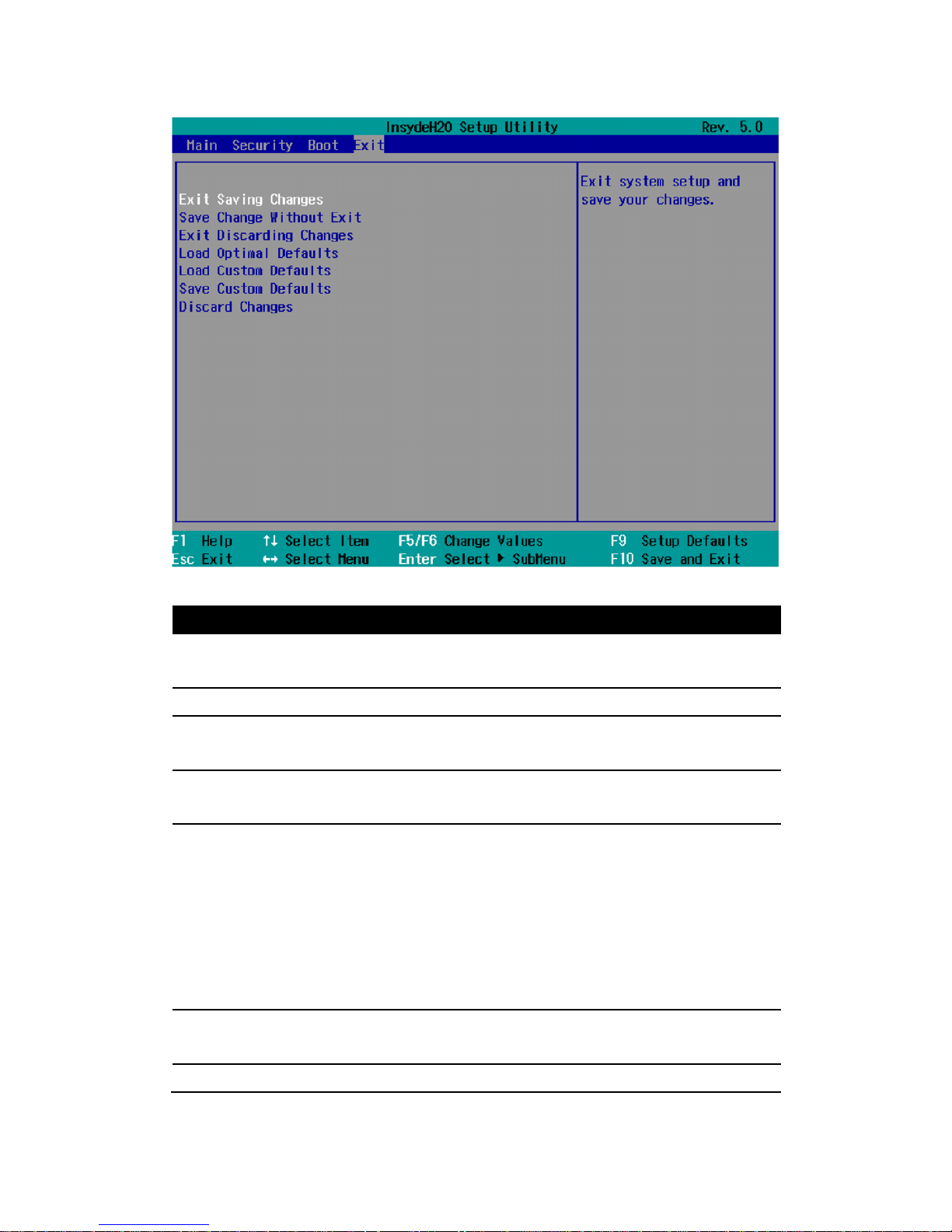
4.3.6 Exit Menu
You always exit BIOS Setup in this menu.
- 29 -
Parameter Meaning
Exit Saving Changes All changes are saved and the system is restarted with the new
setup parameters.
Save Change Without Exit All changes are saved.
Exit Discarding Changes All changes are discarded and the system is restarted with the
old setup parameters.
Load Optimal Defaults All setup parameters are reset to the safe default values.
Notice: The existing setup parameters are overwritten by this.
Load Custom Defaults The profile must be loaded with the custom setup parameters.
Requirement: The parameters are saved prior to this with "Save
Custom Defaults".
Notice: All existing setup parameters are overwritten during
loading.
Write down the BIOS setup settings beforehand
Save the BIOS setup settings as user-specific profile.
Save Custom Defaults The currently configured Setup parameters are saved as a
custom profile (see also "Load Custom Defaults").
Discard Changes All changes are discarded.

- 30 -

- 31 -
Appendix A
Mounting Kits Installation

- 32 -
Ready to Begin?
7”/10.1” CCD supports standard VESA mounting (75x75) to fit field site installation needs. Please read
through these instructions completely to be sure you’re comfortable with this easy install process.
Let’s follow below assembly instructions to begin.
CAUTIONS!
Avoid potential personal injuries and property damage!
The wall must be capable of supporting the weight of CCD and mount combined.
Do not use the mounting kits for any purpose not explicitly specified by
manufacturer.
Manufacturer is not responsible for damage or injury caused by incorrect assembly
or use.
Mounting Instructions
The mounting instructions are described in the following sections using 7” CCD as an example. You can
totally apply the same procedures to 10.1” CCD.
A.1 VESA Mounting Installation
Requirement
▪ 3rd party VESA mount adapter or monitor arm
▪ A PH1 screwdriver
▪ Four screws (4 x M4 4L recommended)
1
- Align the screw holes and attach CCD
to the 3rd party VESA mount adaptor or
monitor arm.
- Secure the back cover of CCD with 4
screws provided by the 3rd party VESA
mount manufacturer and assure all
mounting screws are properly engaged.

- 33 -
Appendix B
Pin Assignments

- 34 -
B.1 HDMI Connector
▲ Figure B.1 HDMI Connector
Pin Name Description
1 HDMI_P2 TMDS data2+
2 GND TMDS data2+ shield
3 HDMI_N2 TMDS data2-
4 HDMI_P1 TMDS data1+
5 GND TMDS data1+ shield
6 HDMI_N1 TMDS data1-
7 HDMI_P0 TMDS data0+
8 GND TMDS data0 shield
9 HDMI_N0 TMDS data0-
10 HDMI_CLKP TMDS clock+
11 GND TMDS clock shield
12 HDMI_CLKN TMDS clock-
13 NC Not Connected
14 NC Not Connected
15 HDMI_CTRL_CLK DDC clock
16 HDMI_CTRL_DAT DDC data
17 GND DDC/CEC ground
18 5V EDID/DDC power
19 HPD Hot Plug Detect
B.2 USB 2.0 Type A Connector

- 35 -
▲ Figure B.2 USB type A Connector
Pin Name Description
1 VCC +5v
2 D- Data-
3 D+ Data+
4 GND Signal ground
B.3 LAN Port (RJ-45)
▲ Figure B.3 LAN RJ-45 Connector
Pin Name Description
1 TX+ Transmit Data+
2 TX- Transmit Data-
3 RX+ Receive Data+
4 NC Not Connected
5 NC Not Connected
6 RX- Receive Data-
7 NC Not Connected
8 NC Not Connected
 Loading...