

Page 1

SENX-KA
AMD Embedded G-Series SOC Quad core / Dual core
processor Nano ITX Motherboard
User’s Manual
1st Ed – 21 April 2014
Part No. E2047SNKA00R
Page 2

SENX-KA User’s Manual
FCC Statement
A Message to the Customer
THIS DEVICE COMPLIES WITH PART 15 FCC RULES. OPERATION IS
SUBJECT TO THE FOLLOWING TWO CONDITIONS:
(1) THIS DEVICE MAY NOT CAUSE HARMFUL INTERFERENCE.
(2) THIS DEVICE MUST ACCEPT ANY INTERFERENCE RECEIVED INCLUDING
INTERFERENCE THAT MAY CAUSE UNDESIRED OPERATION.
THIS EQUIPMENT HAS BEEN TESTED AND FOUND TO COMPLY WITH THE LIMITS
FOR A CLASS "A" DIGITAL DEVICE, PURSUANT TO PART 15 OF THE FCC RULES.
THESE LIMITS ARE DESIGNED TO PROVIDE REASONABLE PROTECTION AGAINST
HARMFUL INTERFERENCE WHEN THE EQUIPMENT IS OPERATED IN A
COMMERCIAL ENVIRONMENT. THIS EQUIPMENT GENERATES, USES, AND CAN
RADIATE RADIO FREQUENCY ENERGY AND, IF NOT INSTATLLED AND USED IN
ACCORDANCE WITH THE INSTRUCTION MANUAL, MAY CAUSE HARMFUL
INTERFERENCE TO RADIO COMMUNICATIONS.
OPERATION OF THIS EQUIPMENT IN A RESIDENTIAL AREA IS LIKELY TO CAUSE
HARMFUL INTERFERENCE IN WHICH CASE THE USER WILL BE REQUIRED TO
CORRECT THE INTERFERENCE AT HIS OWN EXPENSE.
Avalue Customer Services
Each and every Avalue’s product is built to the most exacting specifications to ensure
reliable performance in the harsh and demanding conditions typical of industrial
environments. Whether your new Avalue device is destined for the laboratory or the factory
floor, you can be assured that your product will provide the reliability and ease of operation
for which the name Avalue has come to be known.
Your satisfaction is our primary concern. Here is a guide to Avalue’s customer services. To
ensure you get the full benefit of our services, please follow the instructions below carefully.
Technical Support
We want you to get the maximum performance from your products. So if you run into
technical difficulties, we are here to help. For the most frequently asked questions, you can
easily find answers in your product documentation. These answers are normally a lot more
detailed than the ones we can give over the phone. So please consult the user’s manual
first.
To receive the latest version of the user’s manual; please visit our Web site at:
http://www.avalue.com.tw/
2 SENX-KA User’s Manual
Page 3

SENX-KA User’s Manual
CONTENT
1. Getting Started ............................................................................................................ 5
1.1 Safety Precautions .......................................................................................... 5
1.2 Packing List .................................................................................................... 5
1.3 Document Amendment History ....................................................................... 6
1.4 Manual Objectives .......................................................................................... 7
1.5 Specifications ................................................................................................. 8
1.6 Architecture Overview—Block Diagram........................................................ 10
2. Hardware Configuration ........................................................................................... 11
2.1 Product Overview ......................................................................................... 12
2.2 Installation Procedure ................................................................................... 14
2.3 Connector List .............................................................................................. 15
2.4 Setting Jumpers & Connectors ..................................................................... 17
2.4.1 Serial port connector (JCOM) ................................................................ 17
2.4.2 Front Panel connector (FPANEL1) ........................................................ 17
2.4.3 USB connector (FUSB) ......................................................................... 18
2.4.4 CPU FAN connector (FAN) ................................................................... 18
2.4.5 Battery connector (BAT) ........................................................................ 19
2.4.6 Front Panel Audio Connection Header (F_AUDIO) ............................... 19
3.BIOS Setup .................................................................................................................... 20
3.1 Introduction ................................................................................................... 21
3.2 Starting Setup ............................................................................................... 21
3.3 Using Setup .................................................................................................. 22
3.4 Getting Help ................................................................................................. 23
3.5 In Case of Problems ..................................................................................... 23
3.6 BIOS setup ................................................................................................... 24
3.6.1 Main Menu ............................................................................................ 24
3.6.1.1 System Language ................................................................... 24
3.6.1.2 System Date ........................................................................... 24
3.6.1.3 System Time ........................................................................... 24
3.6.2 Advanced BIOS settings ....................................................................... 25
3.6.2.1 ACPI Settings .......................................................................... 25
3.6.2.2 CPU Configuration .................................................................. 26
3.6.2.3 Onboard Device Configuration ................................................ 27
3.6.2.4 Advanced Power Management ............................................... 28
3.6.2.5 HW Monitor ............................................................................. 29
3.6.3 Chipset ..................................................................................................... 29
SENX-KA User’s Manual 3
Page 4

SENX-KA User’s Manual
3.6.3.1 South Bridge ........................................................................... 30
3.6.3.1.1 SB SATA Configuration .................................................. 31
3.6.4 Boot settings ......................................................................................... 31
3.6.5 Security ................................................................................................. 32
3.6.5.1 Administrator Password .......................................................... 32
3.6.5.2 User Password ........................................................................ 32
3.6.6 Save & Exit ............................................................................................ 33
3.6.6.1 Save Changes and Exit .......................................................... 33
3.6.6.2 Discard Changes and Exit ...................................................... 34
3.6.6.3 Save Changes and Reset ....................................................... 34
3.6.6.4 Discard Changes and Reset ................................................... 34
3.6.6.5 Save Changes ........................................................................ 34
3.6.6.6 Discard Changes .................................................................... 34
3.6.6.7 Restore Defaults ..................................................................... 34
3.6.6.8 Save as User Defaults ............................................................ 34
3.6.6.9 Restore User Defaults ............................................................. 34
4. Drivers Installation....................................................................................................... 35
4.1 Install VGA Driver ......................................................................................... 36
4.2 Install Audio Driver (For Realtek ALC892).................................................... 37
4.3 Install Ethernet Driver (For Realtek 8111E) .................................................. 38
4.4 Install CIR Driver ................................................................ .......................... 39
5. Mechanical Drawing .................................................................................................... 40
4 SENX-KA User’s Manual
Page 5
SENX-KA User’s Manual
1. Getting Started
1.1 Safety Precautions
Warning!
Always completely disconnect the power cord from your
chassis whenever you work with the hardware. Do not
make connections while the power is on. Sensitive
electronic components can be damaged by sudden power
surges. Only experienced electronics personnel should
open the PC chassis.
Caution!
Always ground yourself to remove any static charge before
touching the CPU card. Modern electronic devices are very
sensitive to static electric charges. As a safety precaution,
use a grounding wrist strap at all times. Place all electronic
components in a static-dissipative surface or static-shielded
bag when they are not in the chassis.
Always note that improper disassembling action could cause damage to the
motherboard. We suggest not removing the heatsink without correct
instructions in any circumstance. If you really have to do this, please contact
us for further support.
1.2 Packing List
Before you begin installing your single board, please make sure that the
following materials have been shipped:
Driver/Utility CD X 1
COM Cable X 1
Motherboard X 1
HDD bracket X 1
2.5” HDD Mylar X 1
Screws
SENX-KA User’s Manual 5
Page 6

SENX-KA User’s Manual
Revision
Date
By
Comment
1st
April 2014
Avalue
Initial Release
1.3 Document Amendment History
6 SENX-KA User’s Manual
Page 7

SENX-KA User’s Manual
1.4 Manual Objectives
This manual describes in details Avalue Technology SENX-KA Single Board.
We have tried to include as much information as possible but we have not duplicated
information that is provided in the standard IBM Technical References, unless it proved to
be necessary to aid in the understanding of this board.
We strongly recommend that you study this manual carefully before attempting to set up
SENX-KA series or change the standard configurations. Whilst all the necessary
information is available in this manual we would recommend that unless you are confident,
you contact your supplier for guidance.
If you have any suggestions or find any errors regarding this manual and want to inform us
of these, please contact our Customer Service department with the relevant details.
SENX-KA User’s Manual 7
Page 8
SENX-KA User’s Manual
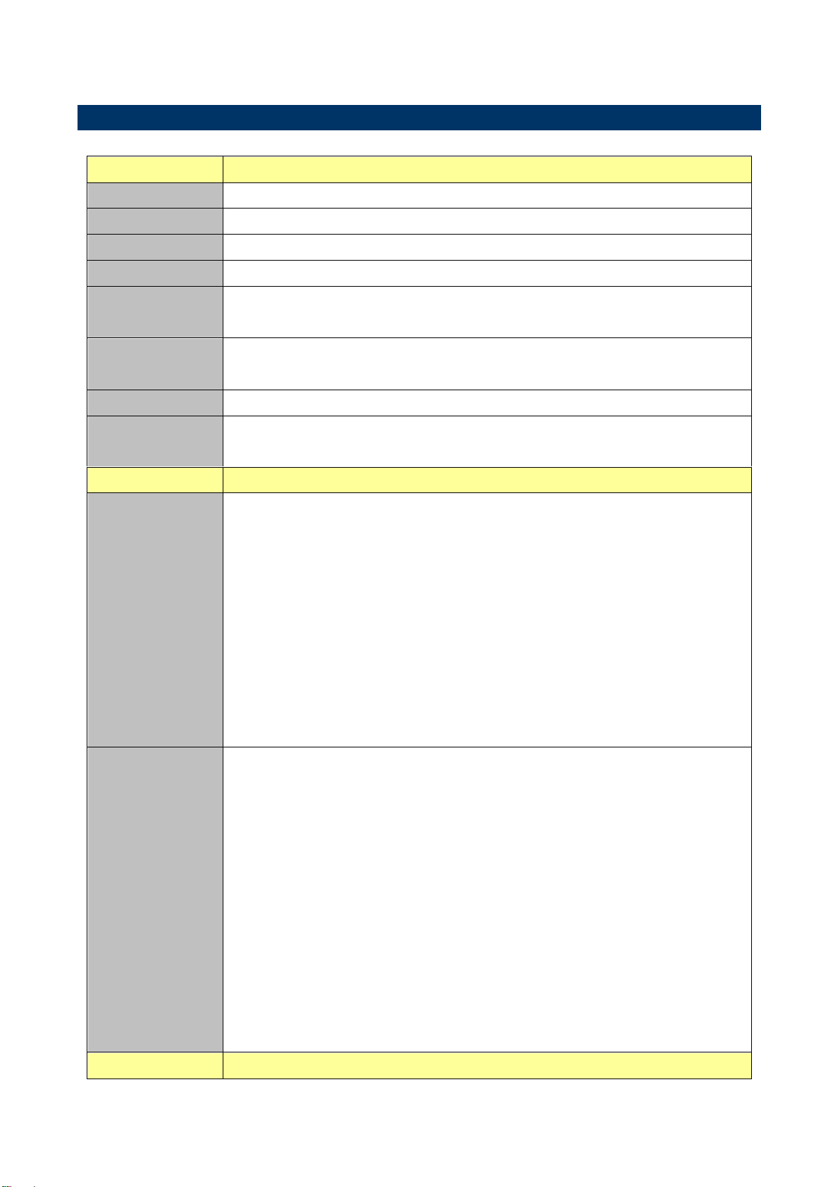
System
CPU
Onboard AMD Embedded G-Series SOC Quad core/Dual core Processor
BIOS
AMI uEFI BIOS 32Mbit SPI Flash ROM
I/O Chip
nuvoTon NCT5532D
System Memory
1 x 204-pin DDR3/DDR3L 1333/1600 SODIMMs, Up to 16 GB
Watchdog Timer
H/W Reset, 1sec. – 65535sec./min.
1sec. or 1min. step
H/W Status
Monitor
CPU & system temperature monitoring
Voltages monitoring
Buzzer
Buzzer onboard
Expansion
1 x half size Mini PCI-e supported mSATA
1 x half size Mini PCI-e supported WiFi
I/O
Rear Side External
I/O Connector
1 x RJ-45
1 x HDMI
1 x Display Port
2 x USB 2.0, 2 x USB 3.0
1 x SD card slot support SD/ SDHC Card
1 x CIR for remote control
1 x S/PDIF
1 x Line-out, 1 x Mic-in
1 x Power button
1 x SMA connector
Internal I/O
Connector
Storage:
- 1 x half size Mini PCI-e supported mSATA
- 1 x SATAIII 7+15 pins combo connector
COM:
- 1 x 1 x 12 pin, pitch 1.25mm connector for COM port , without power
1 x half size Mini PCI-e supported WiFi
1 x 2 x 5 pin, pitch 2.54mm connector for USB 2.0
1 x 1 x 4 pin, pitch 1.25mm connector for CPU Fan connector
1 x 1 x 2 pin, pitch 1.25mm connector battery connector
1 x 2 x 5 pin, pitch 2.54mm connector for front panel
1 x 2 x 5 pin, pitch 2.54mm connector for front audio
1 Pitch 2.5mm DC Jack
Display
1.5 Specifications
8 SENX-KA User’s Manual
Page 9
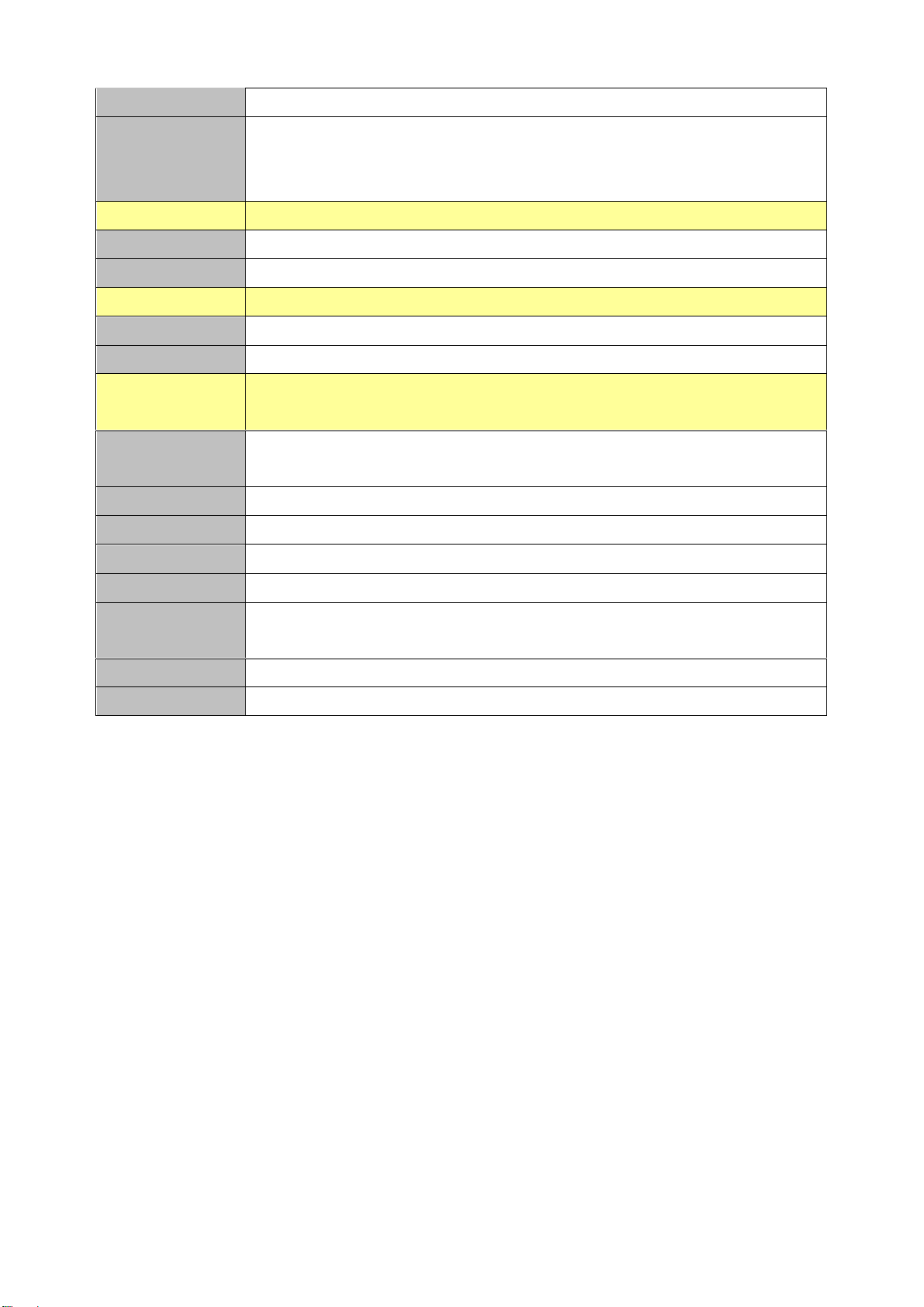
SENX-KA User’s Manual
Chipset
AMD Embedded G-Series integrated
Resolution
Dual display HDMI + Display Port
HDMI 1920 x 1080 @ 60Hz
Display Port 2560 x 1600 @ 60 Hz
Audio
Chipset
Realtek ALC892 HD Audio Decoding Controller
Audio Interface
Mic-In, Line-out
Ethernet
Chipset
1 x Realtek RTL8111E PCI-Express Gigabit Ethernet
Ethernet Interface
10/100/1000 Gigabit Ethernet
Mechanical &
Environmental
Power
Requirement
DC in + 12V
Power Type
ATX mode
ACPI
Support S0, S3, S4, S5
Operating Temp.
0°C ~ 60°C
Storage Temp.
-40°C ~ 75°C
Operating
Humidity
0% ~ 90% relative humidity, non-condensing
Size (L x W)
4.72" x 4.72" (120mm x 120mm)
Weight
0.40 kg
SENX-KA User’s Manual 9
Page 10
SENX-KA User’s Manual
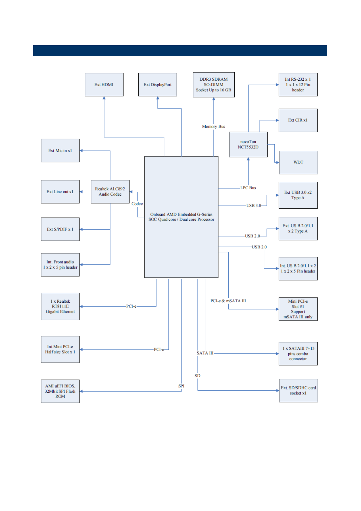
1.6 Architecture Overview—Block Diagram
The following block diagram shows the architecture and main components of SENX-KA.
10 SENX-KA User’s Manual
Page 11

SENX-KA User’s Manual
2. Hardware
Configuration
SENX-KA User’s Manual 11
Page 12
SENX-KA User’s Manual
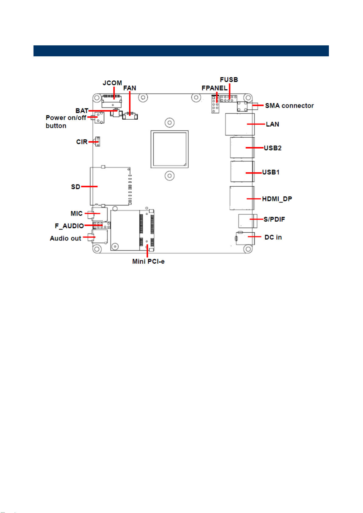
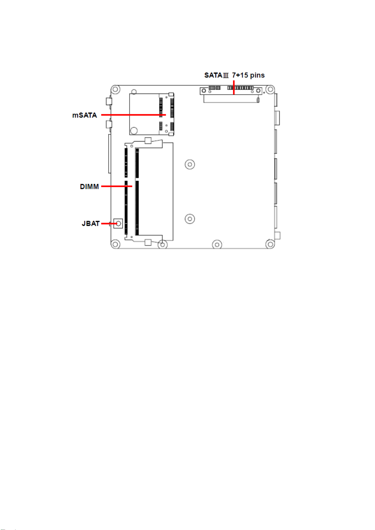
2.1 Product Overview
12 SENX-KA User’s Manual
Page 13
SENX-KA User’s Manual
SENX-KA User’s Manual 13
Page 14

SENX-KA User’s Manual
2.2 Installation Procedure
This chapter explains you the instructions of how to setup your system.
1. Turn off the power supply.
2. Insert the DIMM module (be careful with the orientation).
3. Insert all external cables for hard disk, floppy, keyboard, mouse, USB etc. except for flat
panel. A CRT monitor must be connected in order to change BIOS settings to support flat
panel.
4. Connect power supply to the board via the ATX Power.
5. Turn on the power.
6. Enter the BIOS setup by pressing the delete key during boot up. Use the "Save & Exit \
Restore Defaults" feature.
7. If TFT panel display is to be utilized, make sure the panel voltage is correctly set before
connecting the display cable and turning on the power.
14 SENX-KA User’s Manual
Page 15

SENX-KA User’s Manual
Connectors
Label
Function
Note
FPANEL
Front Panel connector
2 x 5 header, pitch 2.54 mm
Mini PCI-e
PCI-e signal selector
Half size Mini PCI-e slot
HDMI_DP
1 HDMI + 1DP Port
BAT
Battery connector
1 x 2 wafer, pitch 1.25 mm
JBAT1
Clear CMOS
Clear CMOS button
JCOM
Serial port connector
1 x 12 wafer, pitch 1.25 mm
SD
SD card slot support SD/SDHC card
MIC
Mic-in audio jack
Audio out
Line-out audio jack
F_AUDIO
Front Panel Audio Connection Header
2 x 5 header, pitch 2.54 mm
FUSB
USB connector
2 x 5 header, pitch 2.54 mm
2.3 Connector List
You can configure your board to match the needs of your application by setting jumpers. A
jumper is the simplest kind of electric switch.
It consists of two metal pins and a small metal clip (often protected by a plastic cover) that
slides over the pins to connect them. To “close” a jumper you connect the pins with the clip.
To “open” a jumper you remove the clip. Sometimes a jumper will have three pins, labeled 1,
2, and 3. In this case, you would connect either two pins.
The jumper settings are schematically depicted in this manual as follows:
A pair of needle-nose pliers may be helpful when working with jumpers.
Connectors on the board are linked to external devices such as hard disk drives, a
keyboard, or floppy drives. In addition, the board has a number of jumpers that allow you to
configure your system to suit your application.
If you have any doubts about the best hardware configuration for your application, contact
your local distributor or sales representative before you make any changes.
The following tables list the function of each of the board’s jumpers and connectors.
SENX-KA User’s Manual 15
Page 16

SENX-KA User’s Manual
USB1
USB 3.0 Type A connector x 2
USB2
USB 2.0 Type A connector x 2
FAN
CPU Fan connector
1 x 4 wafer, pitch 1.25 mm
SMA connector
Onboard SMA connector
POWER
Power on/off
Power on/off button
DIMM
DDR3/DDR3L SODIMM socket
LAN
RJ-45 Ethernet connector
DC in
DC power-in connector
1 DC Jack, pitch 2.50 mm
mSATA
Support mSATA only
Half size Mini PCI-e slot
SATAⅢ 7+15 pins
Serial ATA connector
7+15 pins combo connector
S/PIDF
Sony/Philips Digital Interface
CIR
Consumer IR
16 SENX-KA User’s Manual
Page 17

SENX-KA User’s Manual
Note:
COM port without power.
1 x 1 x 12 pin, pitch 1.0mm connector for COM port.
PIN
Signal
1
GND
2
NDCDA
3
NSINA
4
NSOUTA
5
NDTRA
6
GND
7
NDSRA
8
NRTSA
9
NCTSA
10
NRIA
11
GND
12
GND
Signal
PIN
PIN
Signal
+5V
1
2
+5V
HDD_LED
3
4
GND
GND
5
6
PWR_BTN_L
RESET_BTN_R
7
8
GND
GND
9
2.4 Setting Jumpers & Connectors
2.4.1 Serial port connector (JCOM)
2.4.2 Front Panel connector (FPANEL1)
SENX-KA User’s Manual 17
Page 18

SENX-KA User’s Manual
Note: USB port doesn’t support S1 mode.
Signal
PIN
PIN
Signal
+5V
1
2
+5V
Data 1 -
3
4
Data 0 -
Data 1+
5
6
Data 0+
GND
7
8
GND
10
GND
PIN
Signal
1
GND
2
VCC
3
SENSE
4
PWM
2.4.3 USB connector (FUSB)
2.4.4 CPU FAN connector (FAN)
18 SENX-KA User’s Manual
Page 19

SENX-KA User’s Manual
PIN
Signal
1
BAT
2
GND
Signal
PIN
PIN
Signal
MIC2-L
1 2 GND
MIC2-R
3 4 NC
LINE2-R
5 6 MIC2-JD
GND
7
LINE2-L
9
10
LINE2 JD
2.4.5 Battery connector (BAT)
2.4.6 Front Panel Audio Connection Header (F_AUDIO)
SENX-KA User’s Manual 19
Page 20

SENX-KA User’s Manual
3.BIOS Setup
20 SENX-KA User’s Manual
Page 21

SENX-KA User’s Manual
3.1 Introduction
The BIOS setup program allows users to modify the basic system configuration. In this
following chapter will describe how to access the BIOS setup program and the
configuration options that may be changed.
3.2 Starting Setup
The BIOS is immediately activated when you first power on the computer. The BIOS reads
the system information contained in the NVRAM and begins the process of checking out
the system and configuring it. When it finishes, the BIOS will seek an operating system on
one of the disks and then launch and turn control over to the operating system.
While the BIOS is in control, the Setup program can be activated in one of two ways:
By pressing <Del> immediately after switching the system on, or
By pressing the <Del> key when the following message appears briefly at the bottom of the
screen during the POST (Power On Self Test).
Press DEL to enter setup, F11 to popup menu
If the message disappears before you respond and you still wish to enter Setup, restart the
system to try again by turning it OFF then ON or pressing the "RESET" button on the
system case. You may also restart by simultaneously pressing <Ctrl>, <Alt>, and <Delete>
keys. If you do not press the keys at the correct time and the system does not boot, an error
message will be displayed and you will again be asked to.
Press DEL to enter setup, F11 to popup menu
SENX-KA User’s Manual 21
Page 22

SENX-KA User’s Manual
Button
Description
↑
Move to previous item
↓
Move to next item
←
Move to the item in the left hand
→
Move to the item in the right hand
Esc key
Main Menu -- Quit and not save changes into NVRAM
Status Page Setup Menu and Option Page Setup Menu -- Exit current page and
return to the pervious page or Main Menu
+ key
Increase the numeric value or make changes
- key
Decrease the numeric value or make changes
F1 key
General help, only for Status Page Setup Menu and Option Page Setup Menu
F7 key
Previous Values
F8 key
Fail-Safe Values
F9 key
Optimized Defaults
F10 key
Save and Exit
3.3 Using Setup
In general, you use the arrow keys to highlight items, press <Enter> to select, use the
PageUp and PageDown keys to change entries, press <F1> for help and press <Esc> to
quit. The following table provides more detail about how to navigate in the Setup program
using the keyboard.
Navigating Through The Menu Bar
Use the left and right arrow keys to choose the menu you want to be in.
Note: Some of the navigation keys differ from one screen to another.
To Display a Sub Menu
Use the arrow keys to move the cursor to the sub menu you want. Then press
<Enter>. A “” pointer marks all sub menus.
22 SENX-KA User’s Manual
Page 23

SENX-KA User’s Manual
3.4 Getting Help
Press F1 to pop up a small help window that describes the appropriate keys to use and the
possible selections for the highlighted item. To exit the Help Window press <Esc> or the F1
key again.
3.5 In Case of Problems
If, after making and saving system changes with Setup, you discover that your computer no
longer is able to boot, the BIOS supports an override to the NVRAM settings which resets
your system to its defaults.
The best advice is to only alter settings which you thoroughly understand. To this end, we
strongly recommend that you avoid making any changes to the chipset defaults. These
defaults have been carefully chosen by both AMI and your systems manufacturer to
provide the absolute maximum performance and reliability. Even a seemingly small change
to the chipset setup has the potential for causing you to use the override.
SENX-KA User’s Manual 23
Page 24

SENX-KA User’s Manual
3.6 BIOS setup
Once you enter the BIOS Setup Utility, the Main Menu will appear on the screen. The Main
Menu allows you to select from several setup functions and exit choices. Use the arrow
keys to select among the items and press <Enter> to accept and enter the sub-menu.
3.6.1 Main Menu
This section allows you to record some basic hardware configurations in your computer and
set the system clock.
3.6.1.1 System Language
This option allows choosing the system default language.
3.6.1.2 System Date
Use the system date option to set the system date. Manually enter the day, month and
year.
3.6.1.3 System Time
Use the system time option to set the system time. Manually enter the hours, minutes and
seconds.
Note: BIOS setup screens shown in this chapter are for reference only, and may
not exactly match what you see on your screen. Visit the Avalue website
(www.avalue.com.tw) to download the latest product and BIOS information.
24 SENX-KA User’s Manual
Page 25

SENX-KA User’s Manual
Item
Options
Description
Enable ACPI Auto Configuration
Disabled
Enabled[Default]
Enables or Disables BIOS ACPI Auto
Configuration.
Enable Hibernation
Disabled
Enabled[Default]
Enables or Disables System ability to
Hibernate (OS/S4 Sleep State). This option
3.6.2 Advanced BIOS settings
This section allows you to configure your CPU and other system devices for basic operation
through the following sub-menus.
3.6.2.1 ACPI Settings
SENX-KA User’s Manual 25
Page 26

SENX-KA User’s Manual
may be not effective with some OS.
ACPI Sleep State
Suspend Disabled
S3 only(Suspend to RAM)
[Default]
Select ACPI sleep state the system will enter
when the SUSPEND button is pressed.
Lock Legacy Resources
Disabled
Enabled[Default]
Enables or Disables Lock of Legacy
Resources.
Item
Options
Description
Cool N Quiet
Disabled
Enabled[Default]
Enable/disable Cool N Quiet function.
C6 Mode
Disabled
Enabled[Default]
Enable/disable C6.
3.6.2.2 CPU Configuration
Use the CPU configuration menu to view detailed CPU specification and configure the
CPU.
26 SENX-KA User’s Manual
Page 27

SENX-KA User’s Manual
Item
Options
Description
HD Audio Azalia Device
Disabled
Enabled[Default]
Onboard Audio Controller.
Onboard Lan Controller
Disabled
Enabled[Default]
Onboard Lan Controller.
Launch PXE OpROM policy
Disabled
Enabled[Default]
Controls the execution of UEFI and Legacy
PXE OpROM.
Enabled ALL Of USB Devices
Disabled
Enabled[Default]
Enable/Disable all USB device.
USB 3.0 Port Enable
Disabled
Enabled[Default]
Disabled USB 2.0 Enable USB 3.0.
Serial Port
Disabled[Default]
Enabled
Enable or Disable Serial Port (COM).
WatchDog Function
Disabled[Default]
Enabled
Disable/Enable WatchDog Function.
3.6.2.3 Onboard Device Configuration
SENX-KA User’s Manual 27
Page 28

SENX-KA User’s Manual
Item
Options
Description
USB Keyboard/Mouse S3 Wake
Disabled
Enabled[Default]
Enabled/Disabled Wakeup From S3 By USB
KB/MS.
Wakeup By PME
Disabled
Enabled[Default]
Wakeup By PME.
Power on By RTC
Disabled[Default]
Enabled
Enable or disable System wake on alarm
event. When enabled, System will wake on the
hr”::min::sec specified.
PWROn After PWR-Fail
Always Off
Always On
Keep Last State
PWROn After PWR-Fail.
3.6.2.4 Advanced Power Management
28 SENX-KA User’s Manual
Page 29

SENX-KA User’s Manual
Item
Options
Description
CPU Fan Mode Setting
Manual Mode
Smart Mode
Full Mode[Default]
1.Full Mode 2.Manual Mode 3.Smart Mode.
3.6.2.5 HW Monitor
The H/W Monitor shows the operating temperature, fan speeds and system voltages.
3.6.3 Chipset
SENX-KA User’s Manual 29
Page 30

SENX-KA User’s Manual
Item
Description
South Bridge
South Bridge parameters.
Item
Description
SB SATA Configuration
Options For SATA Configuration.
3.6.3.1 South Bridge
30 SENX-KA User’s Manual
Page 31

SENX-KA User’s Manual
Item
Options
Description
OnChip SATA Channel
Disabled
Enabled[Default]
OnChip SATA Type
Native IDE[Default]
AHCI
Native IDE AHCI.
3.6.3.1.1 SB SATA Configuration
3.6.4 Boot settings
SENX-KA User’s Manual 31
Page 32

SENX-KA User’s Manual
Item
Option
Description
Setup Prompt Timeout
1-65535
Number of seconds to wait for setup
activation key, 65535(0xFFFF) means
indefinite waiting.
Bootup Numlock State
On [Default]
Off
Select the keyboard NumLock state.
Full Logo Screen
Disabled[Default]
Enabled
Enables or disables Quiet Boot option.
UEFI Boot
Auto[Default]
Enabled
Disabled
Auto: If the 1st boot HDD is GPT then
enable UEFI boot options, otherwise
disable. Enabled: Enable all UEFI boot
options. Disabled: Disabled all UEFI
boot options.
Boot Option #1
Sets the system driver order.
3.6.5 Security
Use the Security menu to set system and user password.
3.6.5.1 Administrator Password
Set Administrator Password.
3.6.5.2 User Password
Set User Password.
32 SENX-KA User’s Manual
Page 33

SENX-KA User’s Manual
3.6.6 Save & Exit
3.6.6.1 Save Changes and Exit
Exit system setup after saving the changes.
F10 key can be used for this operation.
SENX-KA User’s Manual 33
Page 34

SENX-KA User’s Manual
3.6.6.2 Discard Changes and Exit
Exit system setup without saving any changes.
ESC key can be used for this operation.
3.6.6.3 Save Changes and Reset
Reset the system after saving the changes.
3.6.6.4 Discard Changes and Reset
Any changes made to BIOS settings during this session of the BIOS setup program are
discarded. The setup program then exits and reboots the controller.
3.6.6.5 Save Changes
Save Changes done so far to any of the setup options.
3.6.6.6 Discard Changes
Discard Changes done so far to any of the setup options.
3.6.6.7 Restore Defaults
This option restores all BIOS settings to the factory default. This option is useful if the
controller exhibits unpredictable behavior due to an incorrect or inappropriate BIOS setting.
3.6.6.8 Save as User Defaults
Save the changes done so far as User Defaults.
3.6.6.9 Restore User Defaults
Restore the User Defaults to all the setup options.
34 SENX-KA User’s Manual
Page 35

SENX-KA User’s Manual
4. Drivers Installation
Note: Installation procedures and screen shots in this section are for
your reference and may not be exactly the same as shown on
your screen.
SENX-KA User’s Manual 35
Page 36

SENX-KA User’s Manual
Insert the Supporting DVD-ROM to
DVD-ROM drive, and it should show the
index page of Avalue’s products
automatically. If not, locate Index.htm and
choose the product from the menu left.
Note: The installation procedures and
screen shots in this section are based on Windows
7 operation system.
Step 3. Click Yes to complete setup.
Step 1. Click Next to continue installation.
Step 2. Click Next to continue installation.
4.1 Install VGA Driver
36 SENX-KA User’s Manual
Page 37

SENX-KA User’s Manual
Insert the Supporting CD-ROM to CD-ROM
drive, and it should show the index page of
Avalue’s products automatically. If not, locate
Index.htm and choose the product from the
menu left.
Note: The installation procedures and screen
shots in this section are based on
Windows 7 operation system.
Step 1. Click Yes to continue setup.
Step 2. Click Install to complete the setup.
4.2 Install Audio Driver (For Realtek ALC892)
SENX-KA User’s Manual 37
Page 38

SENX-KA User’s Manual
Insert the Supporting DVD-ROM to
DVD-ROM drive, and it should show the
index page of Avalue’s products
automatically. If not, locate Index.htm and
choose the product from the menu left.
Note: The installation procedures and
screen shots in this section are
based on Windows 7 operation
system.
Step 3. Click Finish to complete the
setup.
Step 1. Click Next.
Step 2. Click Install to proceed.
4.3 Install Ethernet Driver (For Realtek 8111E)
38 SENX-KA User’s Manual
Page 39

SENX-KA User’s Manual
Insert the Supporting DVD-ROM to
DVD-ROM drive, and it should show the
index page of Avalue’s products
automatically. If not, locate Index.htm and
choose the product from the menu left.
Note: The installation procedures and
screen shots in this section are
based on Windows 7 operation
system.
Step 3. Click Finish to complete the
setup.
Step 1. Click Next.
Step 2. Click Install to proceed.
4.4 Install CIR Driver
SENX-KA User’s Manual 39
Page 40

SENX-KA User’s Manual
5. Mechanical Drawing
40 SENX-KA User’s Manual
Page 41

SENX-KA User’s Manual
Unit: mm
SENX-KA User’s Manual 41
Page 42

SENX-KA User’s Manual
Unit: mm
42 SENX-KA User’s Manual
 Loading...