

Avalue SEMX-H81 User Manual

SEMX-H81
Intel® H81 Express Chipset
Mini ITX Motherboard
User’s Manual
1st Ed – 05 August 2014
Part No. E2047SM8100R

SEMX-H81 User’s Manual
FCC Statement
Notice
Copyright Notice
Trademark Acknowledgement
Disclaimer
THIS DEVICE COMPLIES WITH PART 15 FCC RULES. OPERATION IS
SUBJECT TO THE FOLLOWING TWO CONDITIONS:
(1) THIS DEVICE MAY NOT CAUSE HARMFUL INTERFERENCE.
(2) THIS DEVICE MUST ACCEPT ANY INTERFERENCE RECEIVED INCLUDING
INTERFERENCE THAT MAY CAUSE UNDESIRED OPERATION.
THIS EQUIPMENT HAS BEEN TESTED AND FOUND TO COMPLY WITH THE LIMITS
FOR A CLASS "A" DIGITAL DEVICE, PURSUANT TO PART 15 OF THE FCC RULES.
THESE LIMITS ARE DESIGNED TO PROVIDE REASONABLE PROTECTION AGAINST
HARMFUL INTERFERENCE WHEN THE EQUIPMENT IS OPERATED IN A
COMMERCIAL ENVIRONMENT. THIS EQUIPMENT GENERATES, USES, AND CAN
RADIATE RADIO FREQUENCY ENERGY AND, IF NOT INSTALLED AND USED IN
ACCORDANCE WITH THE INSTRUCTION MANUAL, MAY CAUSE HARMFUL
INTERFERENCE TO RADIO COMMUNICATIONS.
OPERATION OF THIS EQUIPMENT IN A RESIDENTIAL AREA IS LIKELY TO CAUSE
HARMFUL INTERFERENCE IN WHICH CASE THE USER WILL BE REQUIRED TO
CORRECT THE INTERFERENCE AT HIS OWN EXPENSE.
This guide is designed for experienced users to setup the system within the shortest time.
For detailed information, please always refer to the electronic user's manual.
Copyright 2014 Avalue Technology Inc., ALL RIGHTS RESERVED.
No part of this document may be reproduced, copied, translated, or transmitted in any form
or by any means, electronic or mechanical, for any purpose, without the prior written
permission of the original manufacturer.
Brand and product names are trademarks or registered trademarks of their respective
owners.
Avalue Technology Inc. reserves the right to make changes, without notice, to any product,
including circuits and/or software described or contained in this manual in order to improve
design and/or performance. Avalue Technology assumes no responsibility or liability for the
use of the described product(s), conveys no license or title under any patent, copyright, or
masks work rights to these products, and makes no representations or warranties that
these products are free from patent, copyright, or mask work right infringement, unless
2 SEMX-H81 User’s Manual

SEMX-H81 User’s Manual
Life Support Policy
A Message to the Customer
otherwise specified. Applications that are described in this manual are for illustration
purposes only. Avalue Technology Inc. makes no representation or warranty that such
application will be suitable for the specified use without further testing or modification.
Avalue Technology’s PRODUCTS ARE NOT FOR USE AS CRITICAL COMPONENTS IN
LIFE SUPPORT DEVICES OR SYSTEMS WITHOUT THE PRIOR WRITTEN APPROVAL
OF Avalue Technology Inc.
As used herein:
1. Life support devices or systems are devices or systems which, (a) are
intended for surgical implant into body, or (b) support or sustain life and
whose failure to perform, when properly used in accordance with instructions
for use provided in the labeling, can be reasonably expected to result in
significant injury to the user.
2. A critical component is any component of a life support device or system
whose failure to perform can be reasonably expected to cause the failure
of the life support device or system, or to affect its safety or effectiveness.
Avalue Customer Services
Each and every Avalue’s product is built to the most exacting specifications to ensure
reliable performance in the harsh and demanding conditions typical of industrial
environments. Whether your new Avalue device is destined for the laboratory or the factory
floor, you can be assured that your product will provide the reliability and ease of operation
for which the name Avalue has come to be known.
Your satisfaction is our primary concern. Here is a guide to Avalue’s customer services. To
ensure you get the full benefit of our services, please follow the instructions below carefully.
Technical Support
We want you to get the maximum performance from your products. So if you run into
technical difficulties, we are here to help. For the most frequently asked questions, you can
easily find answers in your product documentation. These answers are normally a lot more
detailed than the ones we can give over the phone. So please consult the user’s manual
first.
To receive the latest version of the user’s manual; please visit our Web site at:
http://www.avalue.com.tw/
SEMX-H81 User’s Manual 3

SEMX-H81 User’s Manual
Content
1. Getting Started ............................................................................................................ 6
1.1 Safety Precautions .......................................................................................... 6
1.2 Packing List .................................................................................................... 6
1.3 Document Amendment History ....................................................................... 7
1.4 Manual Objectives .......................................................................................... 8
1.5 Specifications ................................................................................................. 9
1.6 Architecture Overview—Block Diagram........................................................ 11
2. Hardware Configuration ........................................................................................... 12
2.1 Product Overview ......................................................................................... 13
2.2 Installation Procedure ................................................................................... 14
2.3 Jumper and Connector List .......................................................................... 15
2.4 Setting Jumpers & Connectors ..................................................................... 17
2.4.1 Clear CMOS (JBAT1) ............................................................................ 17
2.4.2 ME update (For Flash BIOS use) (JME) ................................................ 17
2.4.3 Front Panel Switches (FPANEL1) ......................................................... 18
2.4.4 Sony/Philips Digital Interface (JSPDIF) ................................................. 18
2.4.5 Front Panel Audio Connection Header (F_AUDIO) ............................... 19
2.4.6 USB Port Headers – USB2.0 (FUSB7) .................................................. 19
2.4.7 USB Port Headers – USB3.0 (F_USB3.0) ............................................. 20
2.4.8 ATX +12V Power connector (PWR12V) ................................................ 20
2.4.9 ATX Power connector (ATXPWR) ......................................................... 21
2.4.10 Serial port connector (JCOM) ................................................................ 21
2.4.11 Speaker connector (SPEAK) ................................................................. 22
2.4.12 System Fan connector (SFAN) ............................................................. 22
2.4.13 CPU Fan connector (CFAN1) ................................................................ 23
2.4.14 Gigabit LAN (RJ-45) connector (LAN1) ................................................. 23
3.BIOS Setup .................................................................................................................... 24
3.1 Introduction ................................................................................................... 25
3.2 Starting Setup ............................................................................................... 25
3.3 Using Setup .................................................................................................. 26
3.4 Getting Help ................................................................................................. 27
3.5 In Case of Problems ..................................................................................... 27
3.6 BIOS setup ................................................................ ................................... 28
3.6.1 Main Menu ............................................................................................ 28
3.6.1.1 System Language .......................................................................... 28
3.6.1.2 System Date .................................................................................. 28
4 SEMX-H81 User’s Manual

SEMX-H81 User’s Manual
3.6.1.3 System Time .................................................................................. 28
3.6.2 Advanced BIOS settings ....................................................................... 29
3.6.2.1 ACPI Settings ................................................................................ 29
3.6.2.2 Onboard Device Configuration ....................................................... 30
3.6.2.3 CPU Configuration ................................................................ ......... 32
3.6.2.4 PCH-FW Configuration .................................................................. 34
3.6.2.5 Advanced Power Management ...................................................... 35
3.6.2.6 Super IO Configuration .................................................................. 36
3.6.2.7 HW Monitor .................................................................................... 36
3.6.2.8 WatchDog Configuration ................................................................ 37
3.6.2.9 AMI Graphic Output Protocol Policy ............................................... 38
3.6.3 Chipset .................................................................................................. 38
3.6.3.1 South Bridge Configuration ............................................................ 39
3.6.3.2 North Bridge Configuration ............................................................ 40
3.6.4 Boot settings ......................................................................................... 41
3.6.4.1 Boot ............................................................................................... 42
3.6.4.2 CSM parameters ................................ ................................ ............ 42
3.6.5 Security ................................................................................................. 43
3.6.5.1 Administrator Password ................................................................. 43
3.6.5.2 User Password............................................................................... 44
3.6.6 Performance .......................................................................................... 44
3.6.6.1 CPU Configuration ................................................................ ......... 44
3.6.6.2 North Bridge Configuration ............................................................ 45
3.6.6.3 OverVoltage Configuration ............................................................. 46
4. Drivers Installation....................................................................................................... 47
4.1 Install Chipset Driver .................................................................................... 48
4.2 Install VGA Driver ......................................................................................... 49
4.3 Install LAN Driver (For Realtek 8111E Gigabit Ethernet) ............................. 50
4.4 Install Audio Driver (For Realtek ALC892 HD Audio) ................................... 51
4.5 Install USB3.0 Driver .................................................................................... 52
4.6 Install ME Driver ........................................................................................... 53
5. Mechanical Drawing .................................................................................................... 54
SEMX-H81 User’s Manual 5
SEMX-H81 User’s Manual
1. Getting Started
1.1 Safety Precautions
Warning!
Always completely disconnect the power cord from your
chassis whenever you work with the hardware. Do not
make connections while the power is on. Sensitive
electronic components can be damaged by sudden power
surges. Only experienced electronics personnel should
open the PC chassis.
Caution!
Always ground yourself to remove any static charge before
touching the CPU card. Modern electronic devices are very
sensitive to static electric charges. As a safety precaution,
use a grounding wrist strap at all times. Place all electronic
components in a static-dissipative surface or static-shielded
bag when they are not in the chassis.
Always note that improper disassembling action could cause damage to the
motherboard. We suggest not removing the heatsink without correct
instructions in any circumstance. If you really have to do this, please contact
us for further support.
1.2 Packing List
Before you begin installing your single board, please make sure that the
following materials have been shipped:
Driver/Utility CD X 1
Serial ATA Signal Cable X 2
Motherboard X 1
IO Shield X 1
6 SEMX-H81 User’s Manual

SEMX-H81 User’s Manual
Revision
Date
By
Comment
1st
August 2014
Avalue
Initial Release
1.3 Document Amendment History
SEMX-H81 User’s Manual 7

SEMX-H81 User’s Manual
1.4 Manual Objectives
This manual describes in details Avalue Technology SEMX-H81 Single Board.
We have tried to include as much information as possible but we have not duplicated
information that is provided in the standard IBM Technical References, unless it proved to
be necessary to aid in the understanding of this board.
We strongly recommend that you study this manual carefully before attempting to set up
SEMX-H81 series or change the standard configurations. Whilst all the necessary
information is available in this manual we would recommend that unless you are confident,
you contact your supplier for guidance.
If you have any suggestions or find any errors regarding this manual and want to inform us
of these, please contact our Customer Service department with the relevant details.
8 SEMX-H81 User’s Manual
SEMX-H81 User’s Manual
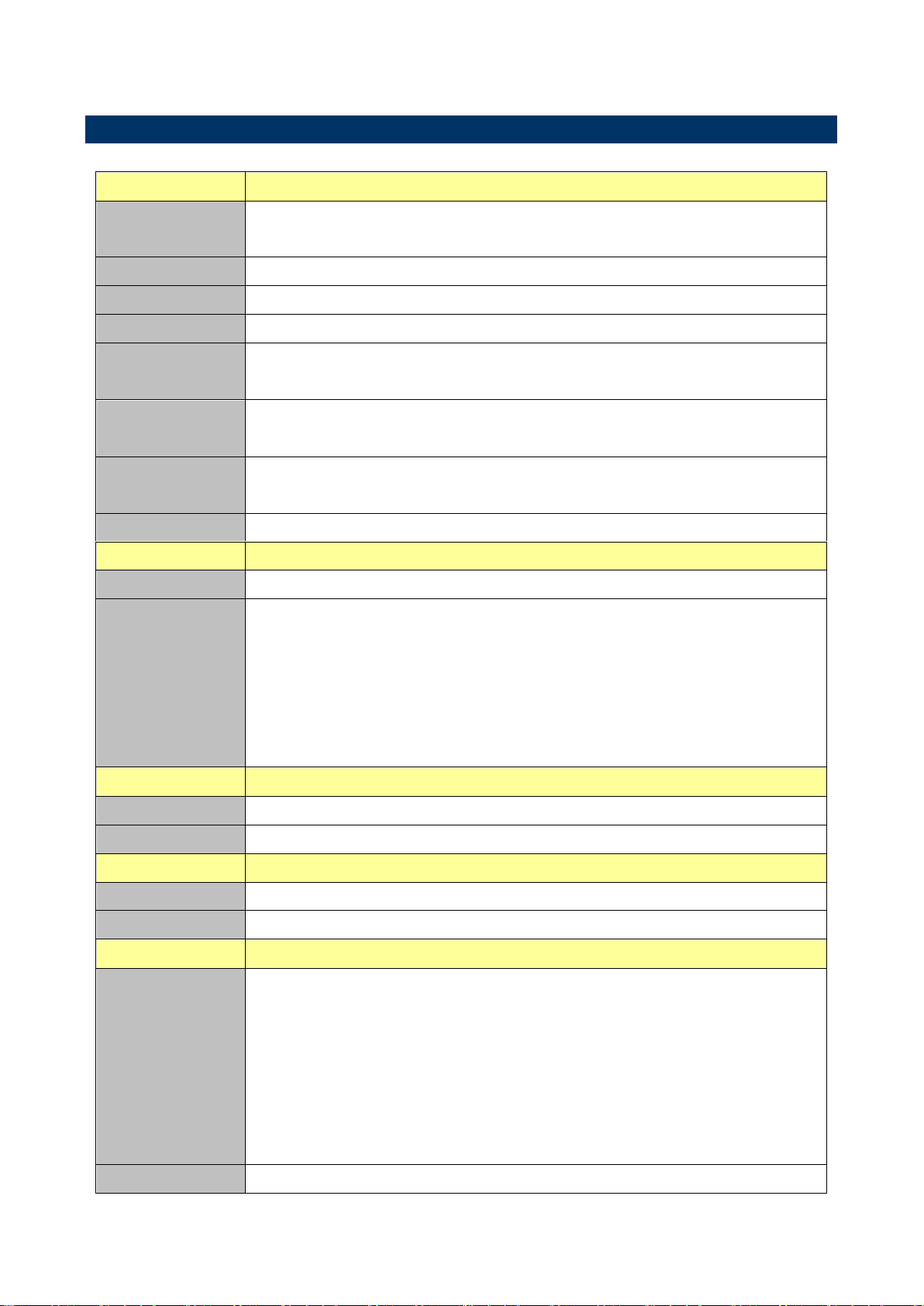
System
CPU
Intel® LGA1150 Socket Supports 4
th
Generation Core™ Refresh i7/ i5/ i3,
Pentium® and Celeron® Processors (Max. TDP at 84W)
BIOS
AMI uEFI BIOS, 128Mbit SPI Flash ROM
System Chipset
Intel® H81 Express Chipset
I/O Chip
Nuvoton NCT5532D
System Memory
Two 240-pin DIMM Sockets Up to 16GB Dual Channel, DDR3 1066/1333
/1600MHz SDRAM
Watchdog Timer
H/W Reset, 1sec. – 65535sec./min.
1sec. or 1min. step
H/W Status
Monitor
CPU & system temperature monitoring
Voltages monitoring
Expansion
1 x PCI-e x 16 Gen.3, 1 x Mini PCI-e full size
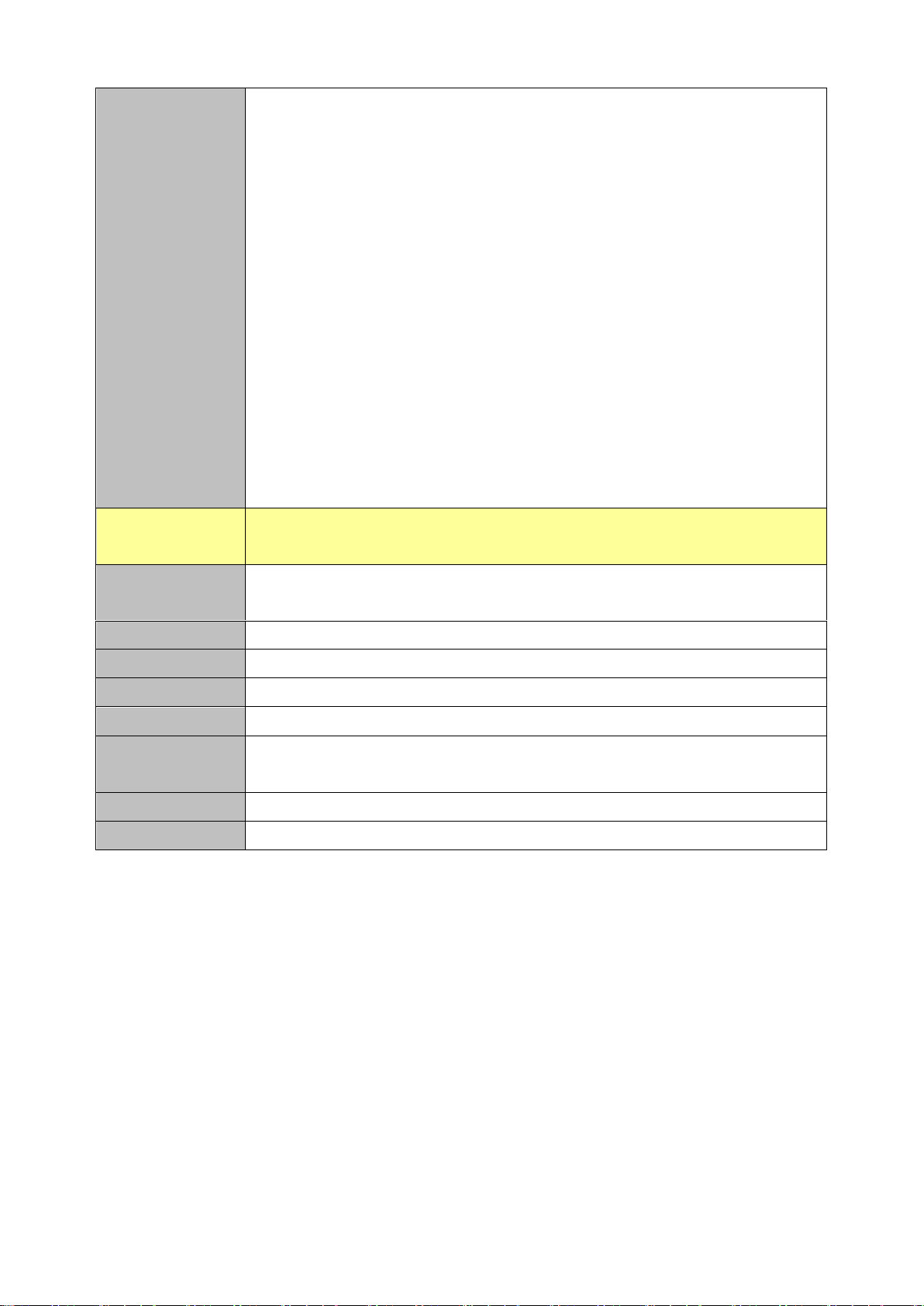
Display
Chipset
Intel® 4th Generation CPU integrated
Resolution
Multi-VGA output support : HDMI/DVI/RGB ports
- Supports HDMI with max. resolution 4096 x 2160 @ 24 Hz / 1920 x 1080 @
60 Hz
- Supports DVI-D with max. resolution 1920 x 1200 @ 60 Hz
- Supports VGA with max. resolution 1920 x 1200 @ 60 Hz
Dual independent displays support with HDMI/DVI and D-Sub
Ethernet
Chipset
1 x Realtek RTL8111E PCI-Express Gigabit Ethernet
Ethernet Interface
10/100/1000 Gigabit Ethernet
Audio
Chipset
Realtek ALC892 HD Audio Decoding Controller
Audio Interface
Line-out, Mic-In, Line-in, Rear R/L, S/PDIF
I/O
Rear Side External
I/O Connector
1 x PS2 Keyboard/Mouse with dual deck USB2.0 connector
1 x RJ-45 with Dual deck USB2.0 connector
1 x Dual deck USB2.0 connector
1 x VGA
1 x HDMI
1 x DVI-D
1 x Line-out, 1 x Mic in, 1 x Line-in, Rear R/L, S/PDIF
Internal I/O
2 x SATA III connector, 2 x SATA II connector
1.5 Specifications
SEMX-H81 User’s Manual 9
SEMX-H81 User’s Manual
Connector
1 x 1 x 5 pin, pitch 2.54mm connector for USB 2.0 support USB 2.0 x 1
1 x 2 x 10 pin, pitch 2.0mm connector for USB 3.0 x 2
1 x 1 x 4 pin, pitch 2.54mm CPU fan connector with smart fan function
supported
1 x 1 x 3 pin, pitch 2.54mm System fan connector
1 x Vertical type battery connector
1 x 2 x 5 pin, pitch 2.54mm connector for front panel
1 x 2 x 5 pin, pitch 2.54mm connector for front Audio
1 x 2 x 5 pin, pitch 2.54mm connector for RS-232 pin 9 without power
1 x 1 x 3 pin, pitch 2.54mm connector for S/PDIF
1 x 1 x 2 pin, pitch 2.54mm connector for BIOS ME flash
1 x 1 x 2 pin, pitch 2.54mm connector for COMS Clear
1 x 1 x 4 pin, pitch 2.54mm connector for Speaker Buzzer
1 x 2 x 10pin ATX power connector
1 x 2 x 2 pin ATX 12V power connector
Mechanical &
Environmental
Power
Requirement
+12V / +5V / 5VSB /+3.3V
Power Type
ATX mode
ACPI
ATX Power Support S0, S3, S4, S5
Operating Temp.
0°C ~60°C
Storage Temp.
-40°C ~75°C
Operating
Humidity
0%~90% relative humidity, non-condensing
Size (L x W)
6.69" x 6.69" (170mm x 170mm)
Weight
0.88lbs 0.40 kg
Note:
The Launch PXE OpROM policy can’t work at UEFI mode. But it can work normally under Legacy mode.
Random Vibration Test (Operation) Test PSD: 0.00202G²/Hz, 1.0 Grms
Random Vibration Test (Non-Operation) Test PSD: 0.01818G²/Hz 3 Grms
*Specifications are subject to change without notice.
10 SEMX-H81 User’s Manual
SEMX-H81 User’s Manual
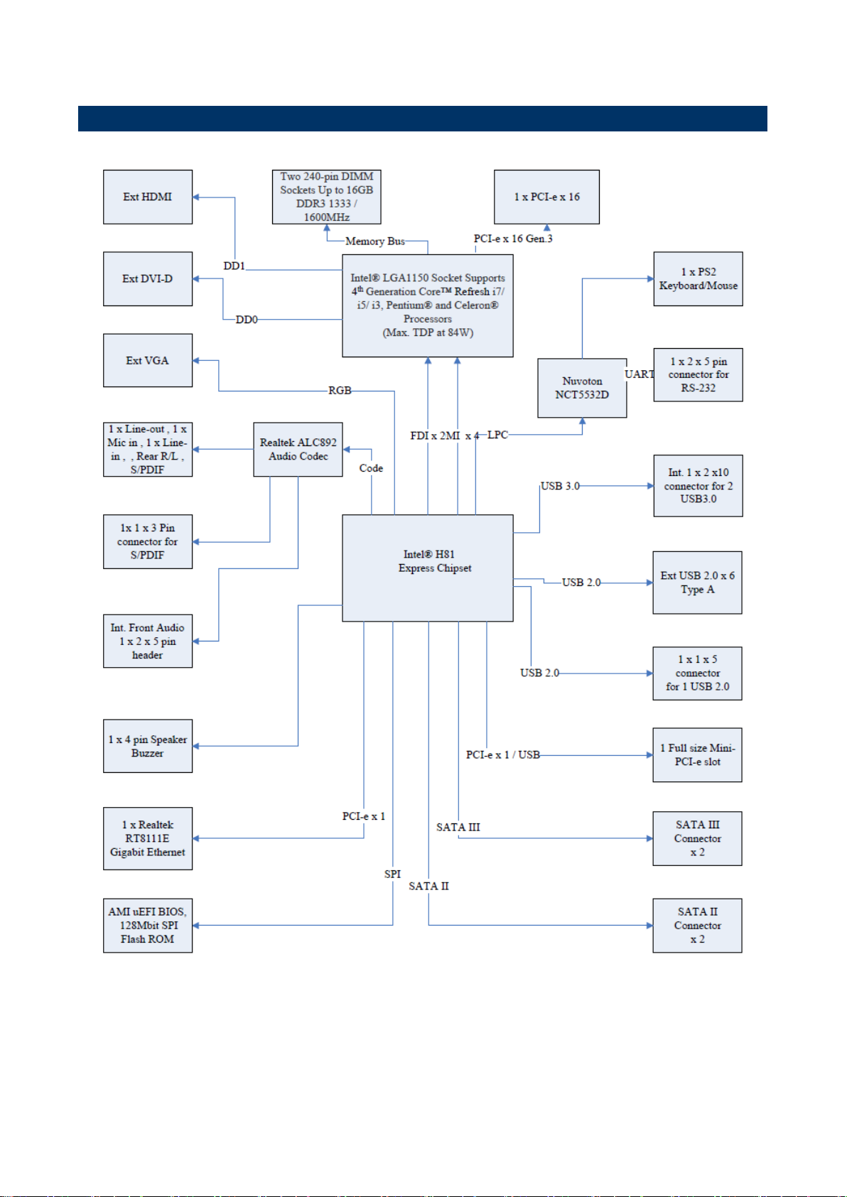
1.6 Architecture Overview—Block Diagram
The following block diagram shows the architecture and main components of SEMX-H81.
SEMX-H81 User’s Manual 11

SEMX-H81 User’s Manual
2. Hardware
Configuration
12 SEMX-H81 User’s Manual
SEMX-H81 User’s Manual
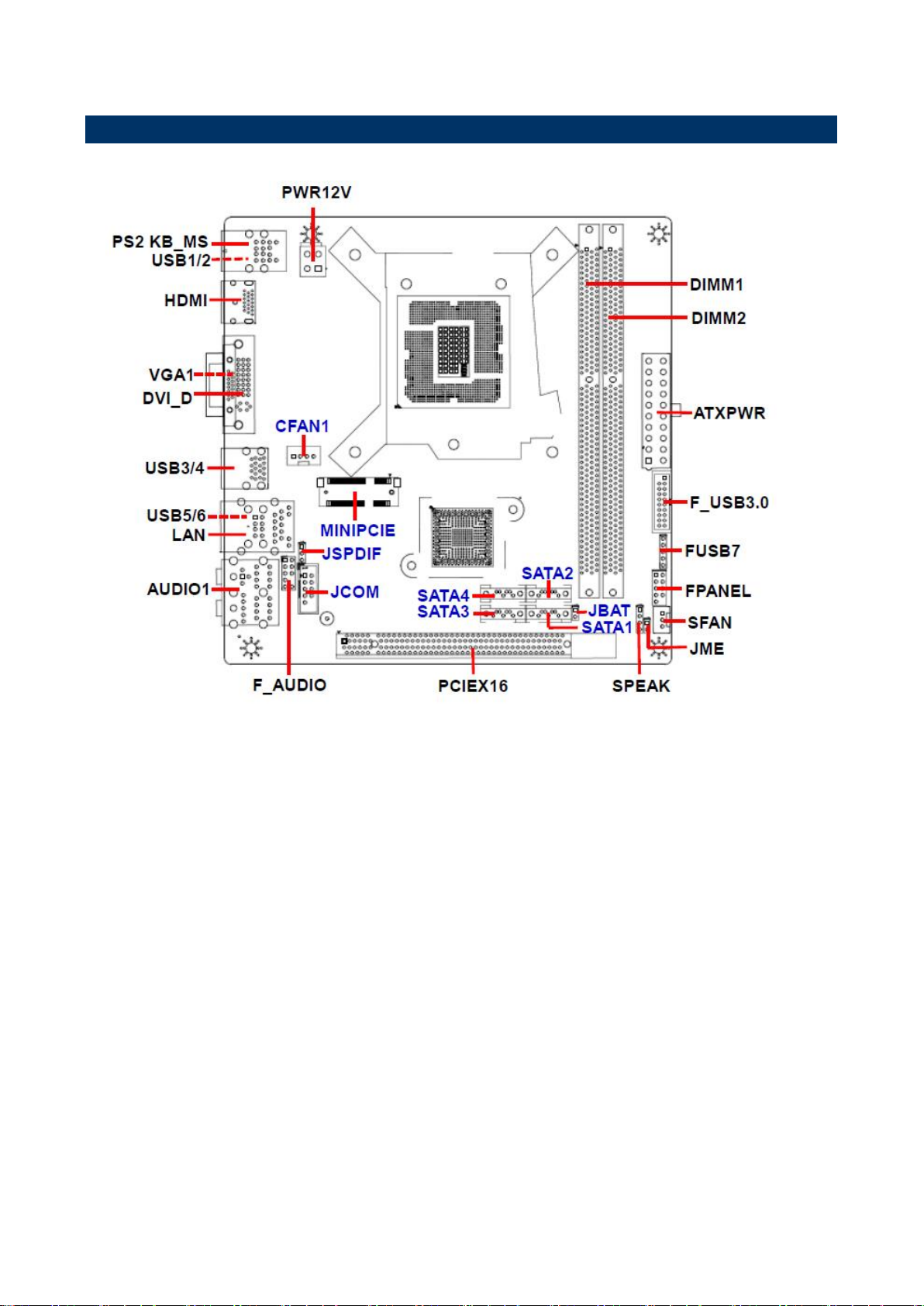
2.1 Product Overview
SEMX-H81 User’s Manual 13

SEMX-H81 User’s Manual
2.2 Installation Procedure
This chapter explains you the instructions of how to setup your system.
1. Turn off the power supply.
2. Insert the DIMM module (be careful with the orientation).
3. Insert all external cables for hard disk, floppy, keyboard, mouse, USB etc. except for flat
panel. A CRT monitor must be connected in order to change BIOS settings to support flat
panel.
4. Connect power supply to the board via the ATX Power.
5. Turn on the power.
6. Enter the BIOS setup by pressing the delete key during boot up. Use the "Save & Exit \
Restore Defaults" feature.
14 SEMX-H81 User’s Manual
SEMX-H81 User’s Manual
Jumpers
Label
Function
Note
JBAT
Clear CMOS
1 x 2 header, pitch 2.54 mm
JME
ME update (For Flash BIOS use)
1 x 2 header, pitch 2.54 mm
Connectors
Label
Function
Note
FPANEL
Front Panel Switches
2 x 5 header, pitch 2.54 mm
PCIEX16
PCI-e x 16
MINIPCIE
Mini-PCI connector
HDMI
HDMI connector
PWR12V
ATX +12V Power connector
2 x 2 wafer, pitch 4.20 mm
ATXPWR
ATX Power connector
2 x 10 wafer, pitch 4.20 mm
2.3 Jumper and Connector List
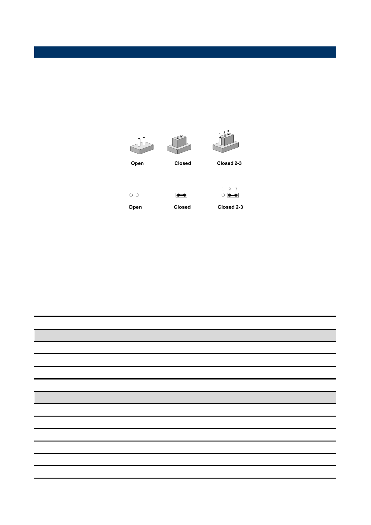
You can configure your board to match the needs of your application by setting jumpers. A
jumper is the simplest kind of electric switch.
It consists of two metal pins and a small metal clip (often protected by a plastic cover) that
slides over the pins to connect them. To “close” a jumper you connect the pins with the clip.
To “open” a jumper you remove the clip. Sometimes a jumper will have three pins, labeled 1,
2, and 3. In this case, you would connect either two pins.
The jumper settings are schematically depicted in this manual as follows:
A pair of needle-nose pliers may be helpful when working with jumpers.
Connectors on the board are linked to external devices such as hard disk drives, a
keyboard, or floppy drives. In addition, the board has a number of jumpers that allow you to
configure your system to suit your application.
If you have any doubts about the best hardware configuration for your application, contact
your local distributor or sales representative before you make any changes.
The following tables list the function of each of the board’s jumpers and connectors.
SEMX-H81 User’s Manual 15

SEMX-H81 User’s Manual
SPEAK
Speaker Headers
1 x 4 header, pitch 2.54 mm
JCOM
Serial port connector
2 x 5 header, pitch 2.54 mm
DVI_D
DVI connector
SATA1~4
Serial ATA connector 1~4
LAN
Gigabit LAN (RJ-45) connector
USB1/2
USB connector 1/2
USB3/4
USB connector 3/4
USB5/6
USB connector 5/6
FUSB7
USB Port Headers (USB 2.0)
1 x 5 header, pitch 2.54 mm
F_USB3.0
USB Port Headers (USB 3.0)
2 x 10 wafer, pitch 2.00 mm
SFAN
System Fan connector
1 x 3 header, pitch 2.54 mm
CFAN1
CPU Fan connector
1 x 4 header, pitch 2.54 mm
DIMM1~2
DDR3 SDRAM DIMM socket
VGA1
VGA connector
F_AUDIO
Front Panel Audio Connection Header
2 x 5 header, pitch 2.54 mm
AUDIO1
Audio connector
JSPDIF
Sony/Philips Digital Interface
1 x 3 header, pitch 2.54 mm
PS2 KB_MS
Keyboard & Mouse
16 SEMX-H81 User’s Manual
SEMX-H81 User’s Manual
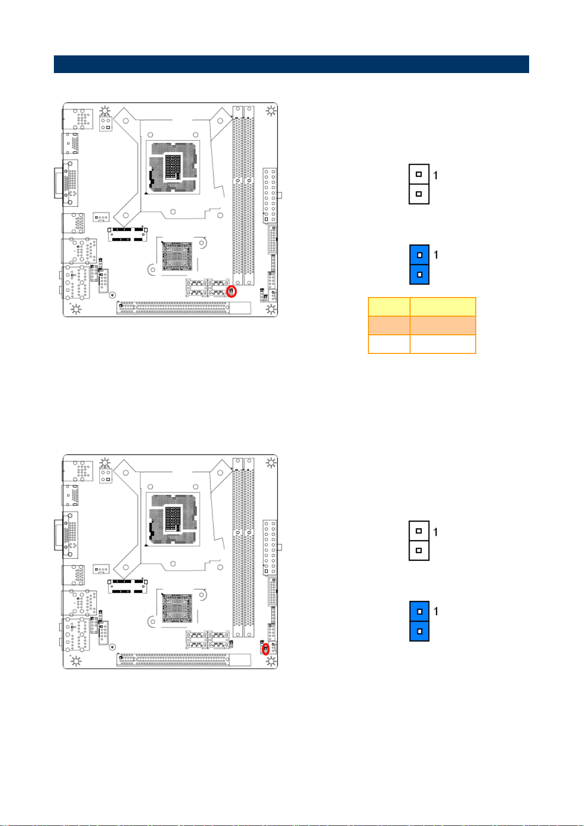
* Default
Normal*
Clear CMOS
Pin
Define
Open
Normal
Short
Clear CMOS
* Default
Open*
Short
2.4 Setting Jumpers & Connectors
2.4.1 Clear CMOS (JBAT1)
2.4.2 ME update (For Flash BIOS use) (JME)
SEMX-H81 User’s Manual 17
 Loading...