


SEAX-H81
Intel® H81 Express Chipset
ATX Motherboard
User’s Manual
1st Ed – 11 August 2014
Part No. E2047SA8100R

SEAX-H81 User’s Manual
FCC Statement
Notice
Copyright Notice
Trademark Acknowledgement
Disclaimer
THIS DEVICE COMPLIES WITH PART 15 FCC RULES. OPERATION IS
SUBJECT TO THE FOLLOWING TWO CONDITIONS:
(1) THIS DEVICE MAY NOT CAUSE HARMFUL INTERFERENCE.
(2) THIS DEVICE MUST ACCEPT ANY INTERFERENCE RECEIVED INCLUDING
INTERFERENCE THAT MAY CAUSE UNDESIRED OPERATION.
THIS EQUIPMENT HAS BEEN TESTED AND FOUND TO COMPLY WITH THE LIMITS
FOR A CLASS "A" DIGITAL DEVICE, PURSUANT TO PART 15 OF THE FCC RULES.
THESE LIMITS ARE DESIGNED TO PROVIDE REASONABLE PROTECTION AGAINST
HARMFUL INTERFERENCE WHEN THE EQUIPMENT IS OPERATED IN A
COMMERCIAL ENVIRONMENT. THIS EQUIPMENT GENERATES, USES, AND CAN
RADIATE RADIO FREQUENCY ENERGY AND, IF NOT INSTALLED AND USED IN
ACCORDANCE WITH THE INSTRUCTION MANUAL, MAY CAUSE HARMFUL
INTERFERENCE TO RADIO COMMUNICATIONS.
OPERATION OF THIS EQUIPMENT IN A RESIDENTIAL AREA IS LIKELY TO CAUSE
HARMFUL INTERFERENCE IN WHICH CASE THE USER WILL BE REQUIRED TO
CORRECT THE INTERFERENCE AT HIS OWN EXPENSE.
This guide is designed for experienced users to setup the system within the shortest time.
For detailed information, please always refer to the electronic user's manual.
Copyright 2014 Avalue Technology Inc., ALL RIGHTS RESERVED.
No part of this document may be reproduced, copied, translated, or transmitted in any form
or by any means, electronic or mechanical, for any purpose, without the prior written
permission of the original manufacturer.
Brand and product names are trademarks or registered trademarks of their respective
owners.
Avalue Technology Inc. reserves the right to make changes, without notice, to any product,
including circuits and/or software described or contained in this manual in order to improve
design and/or performance. Avalue Technology assumes no responsibility or liability for the
use of the described product(s), conveys no license or title under any patent, copyright, or
masks work rights to these products, and makes no representations or warranties that
these products are free from patent, copyright, or mask work right infringement, unless
2 SEAX-H81 User’s Manual

SEAX-H81 User’s Manual
Life Support Policy
A Message to the Customer
otherwise specified. Applications that are described in this manual are for illustration
purposes only. Avalue Technology Inc. makes no representation or warranty that such
application will be suitable for the specified use without further testing or modification.
Avalue Technology’s PRODUCTS ARE NOT FOR USE AS CRITICAL COMPONENTS IN
LIFE SUPPORT DEVICES OR SYSTEMS WITHOUT THE PRIOR WRITTEN APPROVAL
OF Avalue Technology Inc.
As used herein:
1. Life support devices or systems are devices or systems which, (a) are
intended for surgical implant into body, or (b) support or sustain life and
whose failure to perform, when properly used in accordance with instructions
for use provided in the labeling, can be reasonably expected to result in
significant injury to the user.
2. A critical component is any component of a life support device or system
whose failure to perform can be reasonably expected to cause the failure
of the life support device or system, or to affect its safety or effectiveness.
Avalue Customer Services
Each and every Avalue’s product is built to the most exacting specifications to ensure
reliable performance in the harsh and demanding conditions typical of industrial
environments. Whether your new Avalue device is destined for the laboratory or the factory
floor, you can be assured that your product will provide the reliability and ease of operation
for which the name Avalue has come to be known.
Your satisfaction is our primary concern. Here is a guide to Avalue’s customer services. To
ensure you get the full benefit of our services, please follow the instructions below carefully.
Technical Support
We want you to get the maximum performance from your products. So if you run into
technical difficulties, we are here to help. For the most frequently asked questions, you can
easily find answers in your product documentation. These answers are normally a lot more
detailed than the ones we can give over the phone. So please consult the user’s manual
first.
To receive the latest version of the user’s manual; please visit our Web site at:
http://www.avalue.com.tw/
SEAX-H81 User’s Manual 3

SEAX-H81 User’s Manual
Content
1. Getting Started ............................................................................................................ 6
1.1 Safety Precautions .......................................................................................... 6
1.2 Packing List .................................................................................................... 6
1.3 Document Amendment History ....................................................................... 7
1.4 Manual Objectives .......................................................................................... 8
1.5 Specifications ................................................................................................. 9
1.6 Architecture Overview—Block Diagram........................................................ 11
2. Hardware Configuration ........................................................................................... 12
2.1 Product Overview ......................................................................................... 13
2.2 Installation Procedure ................................................................................... 14
2.3 Jumper and Connector List .......................................................................... 15
2.4 Setting Jumpers & Connectors ..................................................................... 17
2.4.1 Clear CMOS (JBAT1) ............................................................................ 17
2.4.2 ME update (For Flash BIOS use) (JME) ................................................ 17
2.4.3 Keyboard power select jumper (JKB) .................................................... 18
2.4.4 Front Panel Switches (FPANEL) ........................................................... 18
2.4.5 Sony/Philips Digital Interface (JSPD_OUT) ........................................... 19
2.4.6 Front Panel Audio Connection Header (F_AUDIO) ............................... 19
2.4.7 USB Port Headers - USB2.0 (FUSB1/2) ............................................... 20
2.4.8 USB Port Headers – USB3.0 (FUSB3.0) ............................................... 20
2.4.9 ATX +12V Power connector (PWR12V) ................................ ................ 21
2.4.10 ATX Power connector (ATXPWR) ......................................................... 21
2.4.11 Serial port connector (JCOM) ................................................................ 22
2.4.12 Speaker connector (SPEAK) ................................................................. 22
2.4.13 System Fan connector (SFAN1) ........................................................... 23
2.4.14 CPU Fan connector (CFAN1) ................................................................ 23
2.4.15 General purpose I/O connector (GPIO) ................................................. 24
2.4.16 LPC connector (JLPC) .......................................................................... 24
2.4.17 Gigabit LAN (RJ-45) connector (LAN) ................................................... 25
3.BIOS Setup .................................................................................................................... 26
3.1 Introduction ................................................................................................... 27
3.2 Starting Setup ............................................................................................... 27
3.3 Using Setup .................................................................................................. 28
3.4 Getting Help ................................................................................................. 29
3.5 In Case of Problems ..................................................................................... 29
3.6 BIOS setup ................................................................................................... 30
4 SEAX-H81 User’s Manual

SEAX-H81 User’s Manual
3.6.1 Main Menu ............................................................................................ 30
3.6.1.1 System Language .......................................................................... 30
3.6.1.2 System Date .................................................................................. 30
3.6.1.3 System Time .................................................................................. 30
3.6.2 Advanced BIOS settings ....................................................................... 31
3.6.2.1 ACPI Settings ................................................................................ 31
3.6.2.2 Onboard Device Configuration ....................................................... 32
3.6.2.3 CPU Configuration ......................................................................... 34
3.6.2.4 Intel® Rapid Start Technology ....................................................... 35
3.6.2.5 PCH-FW Configuration .................................................................. 36
3.6.2.6 Advanced Power Management ...................................................... 37
3.6.2.7 NCT6779D Super IO Configuration ............................................... 38
3.6.2.8 HW Monitor ................................ .................................................... 41
3.6.2.9 WatchDog Configuration ................................................................ 41
3.6.2.10 AMI Graphic Output Protocol Policy ............................................. 42
3.6.3 Chipset .................................................................................................. 43
3.6.3.1 South Bridge Configuration ............................................................ 43
3.6.3.2 North Bridge Configuration ............................................................ 44
3.6.4 Boot settings ......................................................................................... 45
3.6.4.1 CSM parameters ............................................................................ 46
3.6.5 Security ................................................................................................. 47
3.6.5.1 Administrator Password ................................................................. 47
3.6.6 Performance .......................................................................................... 48
3.6.6.1 CPU Configuration ......................................................................... 48
3.6.6.2 North Bridge Configuration ............................................................ 49
3.6.6.3 OverVoltage Configuration ............................................................. 50
4. Drivers Installation....................................................................................................... 51
4.1 Install Chipset Driver .................................................................................... 52
4.2 Install VGA Driver ......................................................................................... 53
4.3 Install LAN Driver (For Realtek 8111E Gigabit Ethernet) ............................. 54
4.4 Install Audio Driver (For Realtek ALC662 HD Audio) ................................... 55
4.5 Install USB3.0 Driver .................................................................................... 56
4.6 Install ME Driver ........................................................................................... 57
5. Mechanical Drawing .................................................................................................... 58
SEAX-H81 User’s Manual 5
SEAX-H81 User’s Manual
1. Getting Started
1.1 Safety Precautions
Warning!
Always completely disconnect the power cord from your
chassis whenever you work with the hardware. Do not
make connections while the power is on. Sensitive
electronic components can be damaged by sudden power
surges. Only experienced electronics personnel should
open the PC chassis.
Caution!
Always ground yourself to remove any static charge before
touching the CPU card. Modern electronic devices are very
sensitive to static electric charges. As a safety precaution,
use a grounding wrist strap at all times. Place all electronic
components in a static-dissipative surface or static-shielded
bag when they are not in the chassis.
Always note that improper disassembling action could cause damage to the
motherboard. We suggest not removing the heatsink without correct
instructions in any circumstance. If you really have to do this, please contact
us for further support.
1.2 Packing List
Before you begin installing your single board, please make sure that the
following materials have been shipped:
Driver/Utility CD X 1
Serial ATA Signal Cable X 2
Motherboard X 1
IO Shield X 1
6 SEAX-H81 User’s Manual

SEAX-H81 User’s Manual
Revision
Date
By
Comment
1st
August 2014
Avalue
Initial Release
1.3 Document Amendment History
SEAX-H81 User’s Manual 7

SEAX-H81 User’s Manual
1.4 Manual Objectives
This manual describes in details Avalue Technology SEAX-H81 Single Board.
We have tried to include as much information as possible but we have not duplicated
information that is provided in the standard IBM Technical References, unless it proved to
be necessary to aid in the understanding of this board.
We strongly recommend that you study this manual carefully before attempting to set up
SEAX-H81 series or change the standard configurations. Whilst all the necessary
information is available in this manual we would recommend that unless you are confident,
you contact your supplier for guidance.
If you have any suggestions or find any errors regarding this manual and want to inform us
of these, please contact our Customer Service department with the relevant details.
8 SEAX-H81 User’s Manual
SEAX-H81 User’s Manual
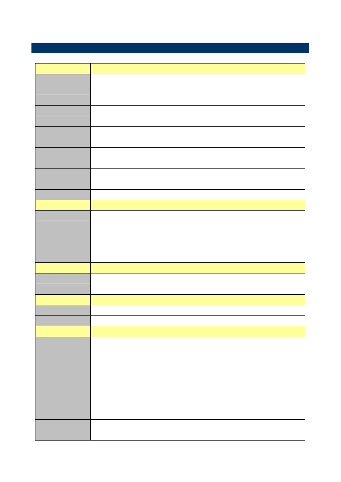
System
CPU
Intel® LGA1150 Socket Supports 4
th
Generation Core™ Refresh i7/ i5/ i3,
Pentium® and Celeron® Processors (Max. TDP at 84W)
BIOS
AMI uEFI BIOS, 64Mbit SPI Flash ROM
System Chipset
Intel® H81 Express Chipset
I/O Chip
Nuvoton NCT6779
System Memory
Two 240-pin DIMM Sockets Up to 16GB Dual Channel,DDR3 1066/ 1333
/1600MHz SDRAM
Watchdog Timer
H/W Reset, 1sec. – 65535sec./min.
1sec. or 1min. step
H/W Status
Monitor
CPU & system temperature monitoring
Voltages monitoring
Expansion
1 x PCI-e x 16 Gen.3, 3 x PCI Express x 1, 3 x PCI
Display
Chipset
Intel® H81 integrated
Resolution
Dual display supported
Supports HDMI with max. resolution 4096 x 2160 @ 24 Hz / 1920 x 1080 @
60 Hz
Supports VGA with max. resolution 1920 x 1200 @ 60 Hz
Ethernet
Chipset
1 x Realtek RTL8111E PCI-Express Gigabit Ethernet
Ethernet Interface
10/100/1000 Gigabit Ethernet
Audio
Chipset
Realtek ALC662 HD Audio Decoding Controller
Audio Interface
Line-out, Mic-In, Line-in
I/O
Rear Side External
I/O Connector
1 x RS-232 DP9 connector, Pin 9 without power
1 x RJ-45 with dual deck USB2.0 connector
1 x Dual deck USB 2.0 connector
1 x VGA
1 x HDMI
1 x Keyboard PS2 and 1 x Mouse PS2
1 x Line-out, 1 x Mic in, 1 x Line-in
1 x Parallel port
Internal I/O
Connector
2 x SATA III connector, 2 x SATA II connector
1 x 2 x 5 pin, pitch 2.54mm connector for RS-232, Pin 9 without power
1.5 Specifications
SEAX-H81 User’s Manual 9
SEAX-H81 User’s Manual
1 x 2 x 5 pin, pitch 2.54mm connector for 8 bit GPIO
2 x 2 x 5 pin, pitch 2.54mm connector for USB 2.0
1 x 2 x 10 pin, pitch 2.0mm connector for USB 3.0 x 2
1 x 1 x 4 pin, pitch 2.54mm CPU fan connector with smart fan function
supported
1 x 1 x 3 pin, pitch 2.54mm System fan connector
1 x horizontal type battery connector
1 x 2 x 5 pin, pitch 2.54mm connector for front panel
1 x 2 x 5 pin, pitch 2.54mm connector for front Audio
1 x 2 x 5 pin, pitch 2.54mm connector for LPC
1 x 1 x 3 pin, pitch 2.54mm connector for SPDIF
1 x 1 x 2 pin, pitch 2.54mm connector for BIOS ME flash
1 x 1 x 2 pin, pitch 2.54mm connector for COMS Clear
1 x 1 x 4 pin, pitch 2.54mm connector for Speaker Buzzer
1 x 1 x 3 pin, pitch 2.54mm connector for Keyboard/Mouse Disable/Enable
1 x 2 x 12 pin ATX power connector
1 x 2 x 4 pin ATX 12V power connector
Mechanical &
Environmental
Power
Requirement
+12V / +5V / 5VSB /+3.3V
Power Type
ATX mode
ACPI
ATX Power Support S0, S3, S4, S5
Operating Temp.
0°C ~60°C
Storage Temp.
-40°C ~75°C
Operating
Humidity
0%~90% relative humidity, non-condensing
Size (L x W)
11.61" x 7.87" (295 mmx 200 mm)
Weight
0.50 kg
Note:
The Launch PXE OpROM policy can’t work at UEFI mode. But it can work normally under Legacy mode.
Random Vibration Test (Operation) Test PSD: 0.00202G²/Hz, 1.0 Grms
Random Vibration Test (Non-Operation) Test PSD: 0.01818G²/Hz 3 Grms
Note: Specifications are subject to change without notice.
10 SEAX-H81 User’s Manual
SEAX-H81 User’s Manual
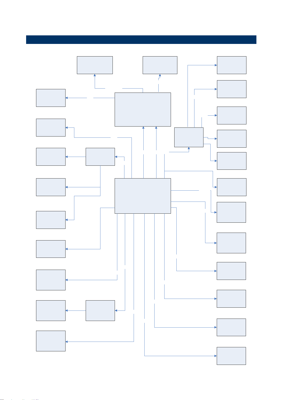
Intel® H81
Express Chipset
Ext USB 2.0 x 4
Type A
Memory Bus
Two 240-pin DIMM
Sockets Up to 16GB
DDR3 1333 /1600MHz
SATA II Connector
x 2
Nuvoton NCT6779
SATA III
Ext VGA
DMI x 4
SPI
UART
AMI uEFI BIOS,
64Mbit SPI Flash
ROM
1 x Line-out , 1 x
Mic in , 1 x Line-in
1 x Realtek
RT8111E
Gigabit Ethernet
PCI-e x 1
SATA II
Ext HDMI
Int. Front Audio
1 x 2 x 5 pin header
Realtek ALC662
Audio Codec
2 x 2 x 5 connector
for 4 USB 2.0
1 x 4 pin Speaker
Buzzer
LPC
1 x PS2 Keyboard
1 x PS2 Mouse
1 DB9 connector
for
RS-232
Int 1 x 2 x 10
conncetor for
2 USB 3.0
USB 3.0
1x 1 x 3 Pin
connector for
S/PDIF
SATA III Connector
x 2
USB 2.0
Intel® LGA1150 Socket Supports 4th
Generation Core™ Refresh i7/ i5/ i3,
Pentium® and Celeron® Processors
(Max. TDP at 84W)
Code
1 x PCI-e x 16
PCI-e x 16 Gen.3
FDI x 2
RGB
DD1
1 x Parallel port
connector
USB 2.0
1 x 2 x 5 connector
for LPC
3 x PCI
3 x PCI-e x 1
asmedia
ASM1083
PCI-e x 1
PCI-e x 1
1 x 2 x 5 connector
for RS-232
UART
1 x 2 x 5 connector
for 8 bit GPIO
1.6 Architecture Overview—Block Diagram
The following block diagram shows the architecture and main components of SEAX-H81.
SEAX-H81 User’s Manual 11

SEAX-H81 User’s Manual
2. Hardware
Configuration
12 SEAX-H81 User’s Manual
SEAX-H81 User’s Manual
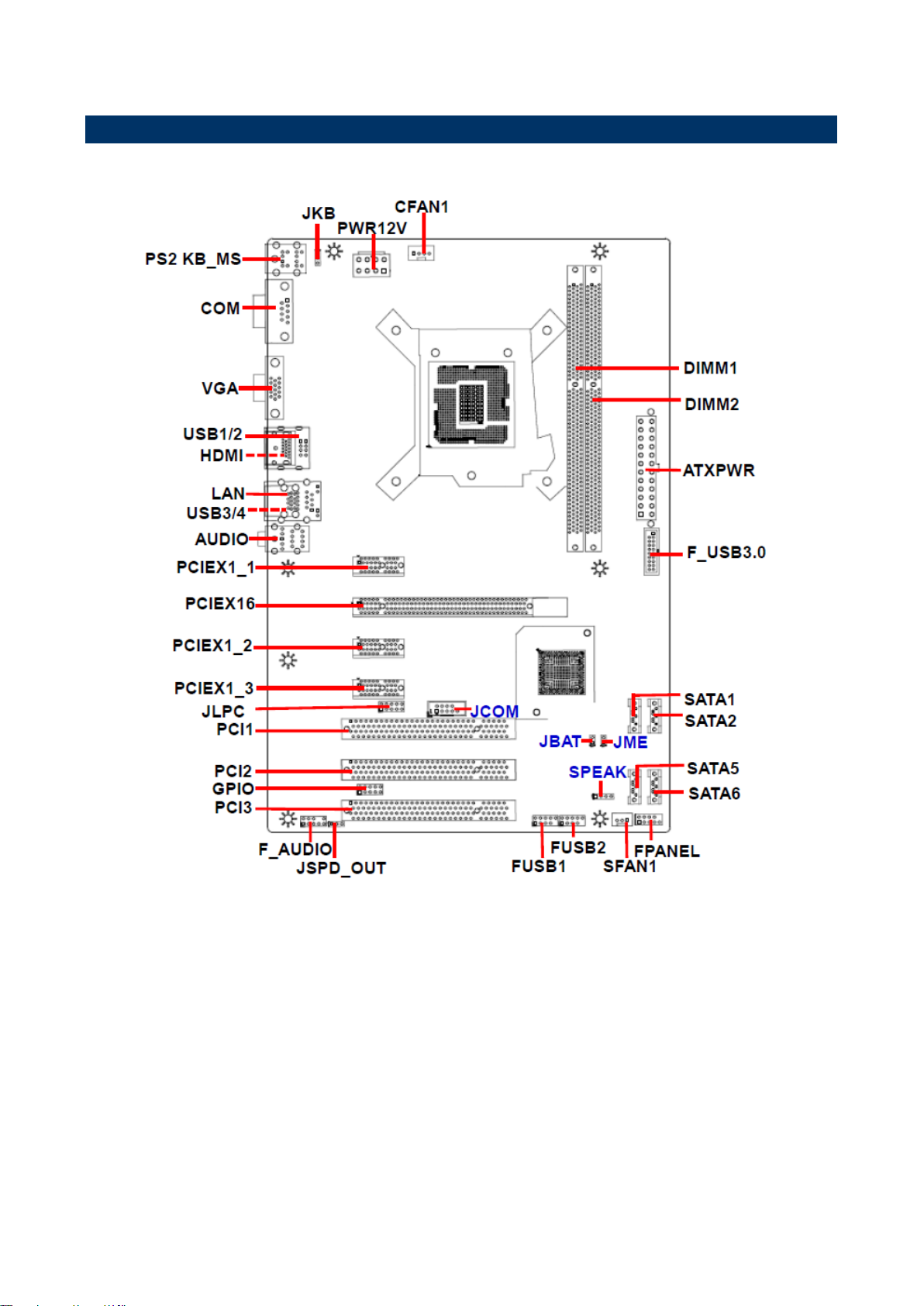
2.1 Product Overview
SEAX-H81 User’s Manual 13

SEAX-H81 User’s Manual
2.2 Installation Procedure
This chapter explains you the instructions of how to setup your system.
1. Turn off the power supply.
2. Insert the DIMM module (be careful with the orientation).
3. Insert all external cables for hard disk, floppy, keyboard, mouse, USB etc. except for flat
panel. A CRT monitor must be connected in order to change BIOS settings to support flat
panel.
4. Connect power supply to the board via the ATX Power.
5. Turn on the power.
6. Enter the BIOS setup by pressing the delete key during boot up. Use the "Save & Exit \
Restore Defaults" feature.
14 SEAX-H81 User’s Manual
SEAX-H81 User’s Manual
Jumpers
Label
Function
Note
JKB
Keyboard power select jumper
1 x 3 header, pitch 2.54 mm
JBAT
Clear CMOS
1 x 2 header, pitch 2.54 mm
JME
ME update (For Flash BIOS use)
1 x 2 header, pitch 2.54 mm
Connectors
Label
Function
Note
FPANEL
Front Panel Switches
2 x 5 header, pitch 2.54 mm
PCIEX16
PCI-e x 16
PCIE1_1
PCI Express x 1 connector 1
PCIE1_2
PCI Express x 1 connector 2
PCIE1_3
PCI Express x 1 connector 3
2.3 Jumper and Connector List
You can configure your board to match the needs of your application by setting jumpers. A
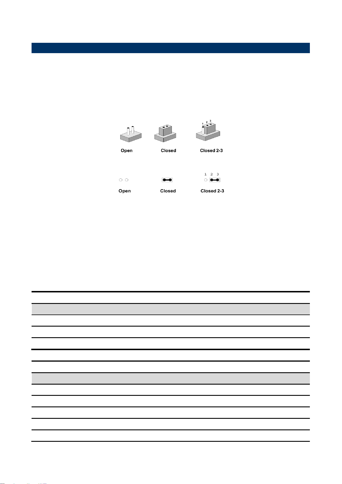
jumper is the simplest kind of electric switch.
It consists of two metal pins and a small metal clip (often protected by a plastic cover) that
slides over the pins to connect them. To “close” a jumper you connect the pins with the clip.
To “open” a jumper you remove the clip. Sometimes a jumper will have three pins, labeled 1,
2, and 3. In this case, you would connect either two pins.
The jumper settings are schematically depicted in this manual as follows:
A pair of needle-nose pliers may be helpful when working with jumpers.
Connectors on the board are linked to external devices such as hard disk drives, a
keyboard, or floppy drives. In addition, the board has a number of jumpers that allow you to
configure your system to suit your application.
If you have any doubts about the best hardware configuration for your application, contact
your local distributor or sales representative before you make any changes.
The following tables list the function of each of the board’s jumpers and connectors.
SEAX-H81 User’s Manual 15

SEAX-H81 User’s Manual
PCI1/2/3
PCI slot 1/2/3
GPIO
General purpose I/O connector
2 x 5 header, pitch 2.54 mm
HDMI
HDMI connector
PWR12V
ATX +12V Power connector
2 x 4 wafer, pitch 4.20 mm
ATXPWR
ATX Power connector
2 x 10 wafer, pitch 4.20 mm
SPEAK
Speaker Headers
1 x 4 header, pitch 2.54 mm
COM
DE-9 male Serial port connector
JCOM
Serial port connector
2 x 5 header, pitch 2.54 mm
SATA1/2/5/6
Serial ATA connector 1/2/5/6
LAN
RJ-45 Ethernet
USB1/2
USB connector 1/2
USB3/4
USB connector 3/4
FUSB1/2
USB Port Headers (USB 2.0)
2 x 2 x 5 header, pitch 2.54
mm
F_USB3.0
USB Port Headers (USB 3.0)
2 x 10 wafer, pitch 2.00 mm
SFAN1
System Fan connector
1 x 3 header, pitch 2.54 mm
CFAN1
CPU Fan connector
1 x 4 header, pitch 2.54 mm
DIMM1~2
DDR3 SDRAM DIMM socket
VGA
VGA connector
F_AUDIO
Front Panel Audio Connection Header
2 x 5 header, pitch 2.54 mm
AUDIO
Audio connector
JSPD_OUT
Sony/Philips Digital Interface
1 x 3 header, pitch 2.54 mm
PS2 KB_MS
Keyboard & Mouse
JLPC
LPC connector
2 x 5 header, pitch 2.54 mm
16 SEAX-H81 User’s Manual
SEAX-H81 User’s Manual
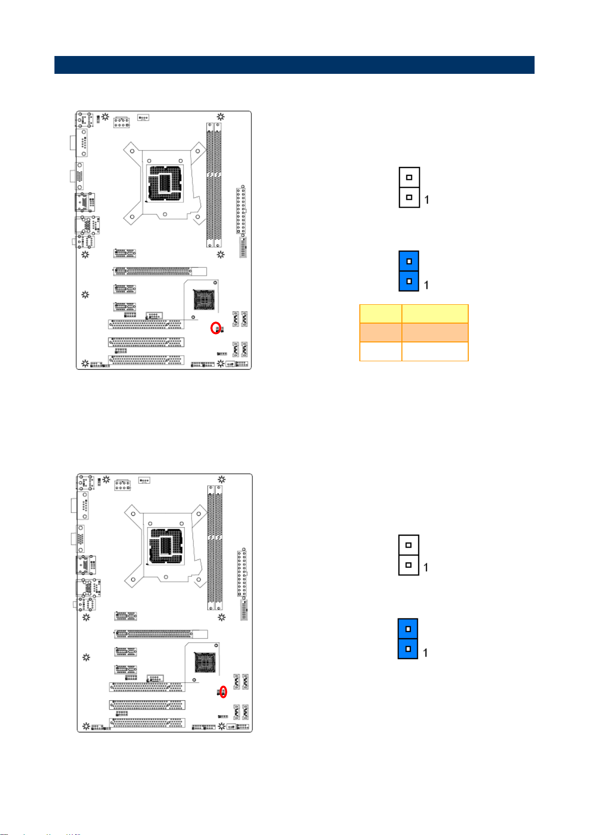
* Default
Normal*
Clear CMOS
Pin
Define
Open
Normal
Short
Clear CMOS
* Default
Open*
Short
2.4 Setting Jumpers & Connectors
2.4.1 Clear CMOS (JBAT1)
2.4.2 ME update (For Flash BIOS use) (JME)
SEAX-H81 User’s Manual 17
SEAX-H81 User’s Manual
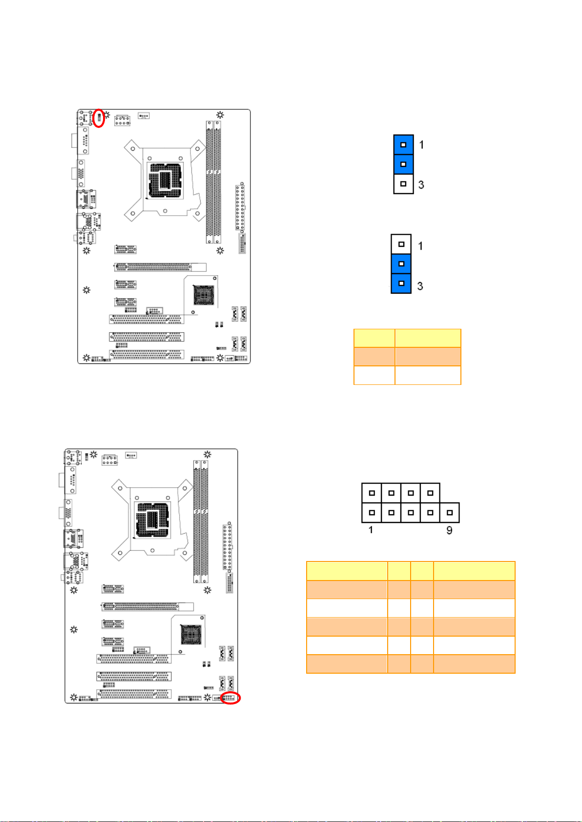
* Default
Disabled*
Enabled
Pin
Define
1-2
Disabled
2-3
Enabled
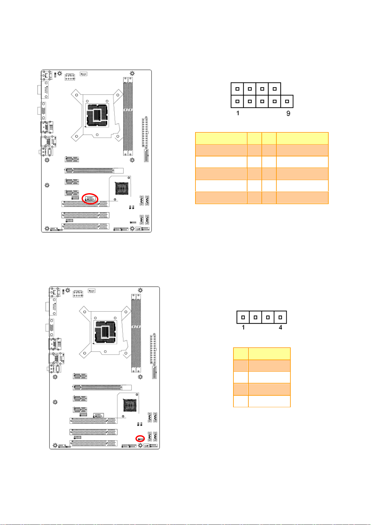
Signal
PIN
PIN
Signal
+HD_LED
1
2
+P_LED
-HD_LED
3
4
-P_LED
RST
5
6
PWR_ON
RST
7
8
-PWR_ON
NC
9
2.4.3 Keyboard power select jumper (JKB)
2.4.4 Front Panel Switches (FPANEL)
18 SEAX-H81 User’s Manual

SEAX-H81 User’s Manual
PIN
Signal
1
VCC
2
OUT
3
GND
Signal
PIN
PIN
Signal
PORT1L
1 2 GND
PORT1R
3 4 PRESENCE#
PORT2R
5 6 SENSE1_RETURN
SENSE_SEND
7
PORT2L
9
10
SENSE2_RETURN
2.4.5 Sony/Philips Digital Interface (JSPD_OUT)
2.4.6 Front Panel Audio Connection Header (F_AUDIO)
SEAX-H81 User’s Manual 19

SEAX-H81 User’s Manual
Signal
PIN
PIN
Signal
VCC
1 2 VCC
DATA -
3 4 DATA -
DATA +
5 6 DATA +
GND
7 8 GND
10
NC
Signal
PIN
PIN
Signal
1 VCC
VCC
19 2 SSRX-
SSRX-
18 3 SSRX+
SSRX+
17 4 GND
GND
16 5 SSTX-
SSTX-
15 6 SSTX+
SSTX+
14 7 GND
GND
13 8 D-
D-
12 9 D+
D+
11
10
ID
FUSB1
FUSB2
2.4.7 USB Port Headers - USB2.0 (FUSB1/2)
2.4.8 USB Port Headers – USB3.0 (FUSB3.0)
20 SEAX-H81 User’s Manual

SEAX-H81 User’s Manual
Signal
PIN
PIN
Signal
GND
1 5 +12V
GND
2 6 +12V
GND
3 7 +12V
GND
4 8 +12V
Signal
PIN
PIN
Signal
+3.3V
12
24
GND
+12V
11
23
+5V
+12V
10
22
+5V
5VSB
9
21
+5V
PWRGD
8
20
NC
GND
7
19
GND
+5V
6
18
GND
GND
5
17
GND
+5V
4
16
PS-ON
GND
3
15
GND
+3.3V
2
14
-12V
+3.3V
1
13
+3.3V
2.4.9 ATX +12V Power connector (PWR12V)
2.4.10 ATX Power connector (ATXPWR)
SEAX-H81 User’s Manual 21
SEAX-H81 User’s Manual
Signal
PIN
PIN
Signal
NDCDB
1 2 NSINB
NSOUTB
3 4 NDTRB
GND
5 6 NDSRB
NRTSB
7 8 NCTSB
NRIB
9
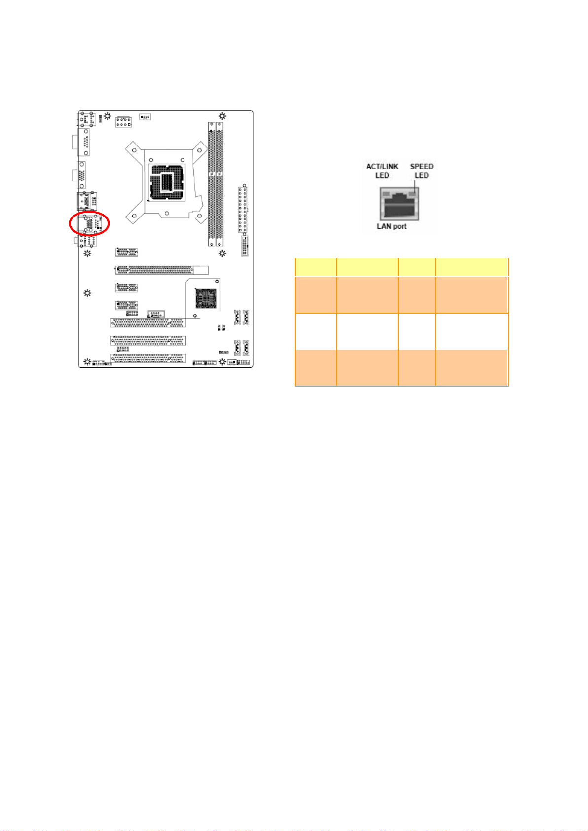
PIN
Signal
1
INTSPL+
2
NC 3 NC
4
INTSPR-
2.4.11 Serial port connector (JCOM)
2.4.12 Speaker connector (SPEAK)
22 SEAX-H81 User’s Manual

SEAX-H81 User’s Manual
PIN
Signal
1
RPM
2
+12V
3
Ground
PIN
Signal
1
Ground
2
+12V
3
RPM
4
Control
2.4.13 System Fan connector (SFAN1)
2.4.14 CPU Fan connector (CFAN1)
SEAX-H81 User’s Manual 23

SEAX-H81 User’s Manual
Signal
PIN
PIN
Signal
VCC3
1 2 GND
6779_GPI0
3 4 6779_GPO4
6779_GPI1
5 6 6779_GPO5
6779_GPI2
7 8 6779_GPO6
6779_GPI3
9
10
6779_GPO7
Signal
PIN
PIN
Signal
L_AD3
1 2 VCC3
L_AD2
3 4 PLTRST_BUF
L_AD1
5 6 L_FRAME_N
L_AD0
7 8 CLK_PCI_DUG
NC
9
2.4.15 General purpose I/O connector (GPIO)
2.4.16 LPC connector (JLPC)
24 SEAX-H81 User’s Manual
SEAX-H81 User’s Manual
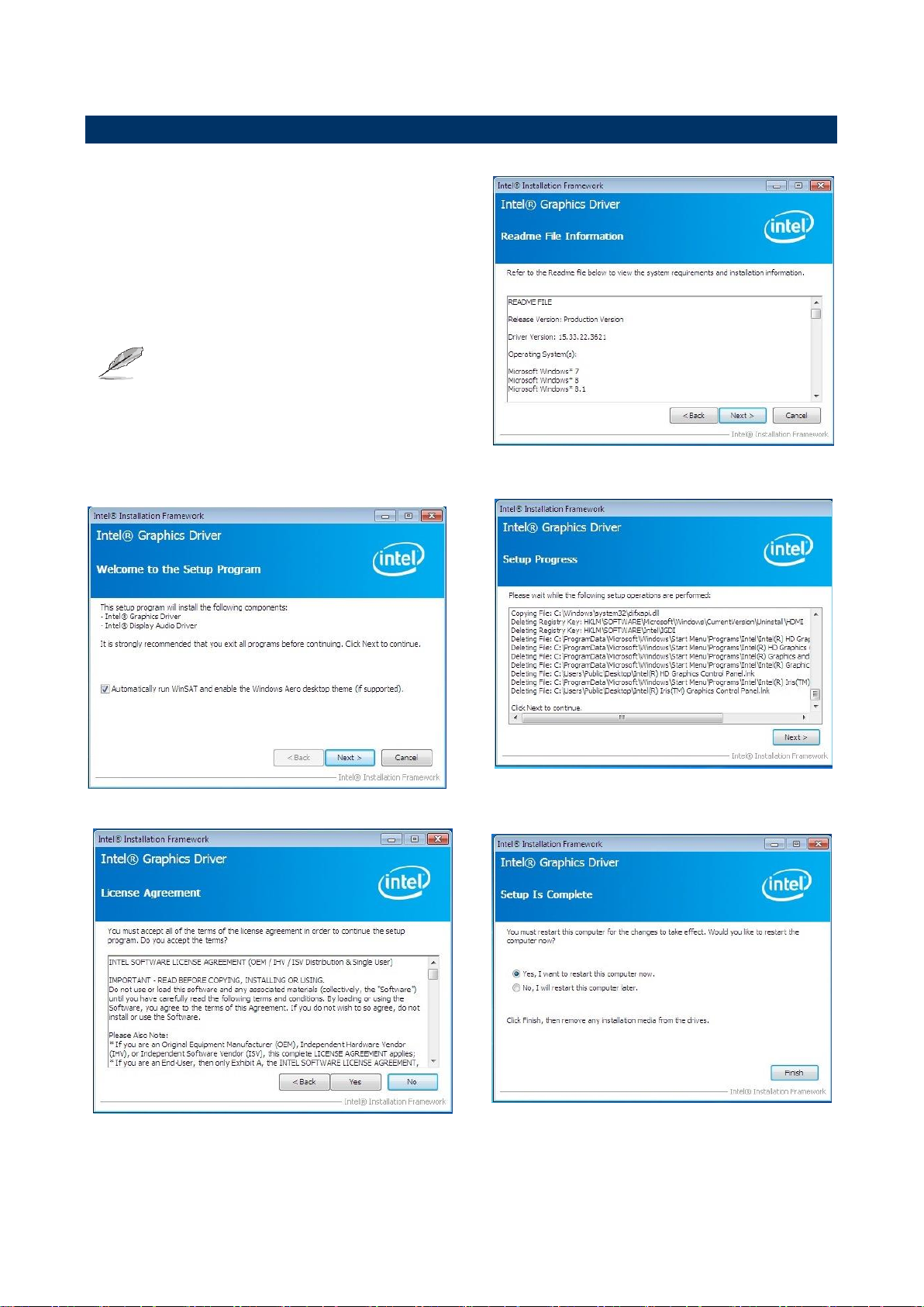
Note:
This port allows Gigabit connection to a Local
Area Network (LAN) through a network hub.
Refer to the table below for the LAN port LED
indications.
Status
Description
Status
Description
OFF
No Light
OFF
10Mbps
connection
Orange
Linked
Green
100Mbps
connection
Blinking
Data activity
Green
1Gbps
connection
2.4.17 Gigabit LAN (RJ-45) connector (LAN)
SEAX-H81 User’s Manual 25

SEAX-H81 User’s Manual
3.BIOS Setup
26 SEAX-H81 User’s Manual

SEAX-H81 User’s Manual
3.1 Introduction
The BIOS setup program allows users to modify the basic system configuration. In this
following chapter will describe how to access the BIOS setup program and the
configuration options that may be changed.
3.2 Starting Setup
The BIOS is immediately activated when you first power on the computer. The BIOS reads
the system information contained in the NVRAM and begins the process of checking out
the system and configuring it. When it finishes, the BIOS will seek an operating system on
one of the disks and then launch and turn control over to the operating system.
While the BIOS is in control, the Setup program can be activated in one of two ways:
By pressing <Del> immediately after switching the system on, or
By pressing the <Del> key when the following message appears briefly at the bottom of the
screen during the POST (Power On Self Test).
Press DEL to enter setup, F11 to popup menu
If the message disappears before you respond and you still wish to enter Setup, restart the
system to try again by turning it OFF then ON or pressing the "RESET" button on the
system case. You may also restart by simultaneously pressing <Ctrl>, <Alt>, and <Delete>
keys. If you do not press the keys at the correct time and the system does not boot, an error
message will be displayed and you will again be asked to.
Press DEL to enter setup, F11 to popup menu
SEAX-H81 User’s Manual 27

SEAX-H81 User’s Manual
Button
Description
↑
Move to previous item
↓
Move to next item
←
Move to the item in the left hand
→
Move to the item in the right hand
Esc key
Main Menu -- Quit and not save changes into NVRAM
Status Page Setup Menu and Option Page Setup Menu -- Exit current page and
return to the pervious page or Main Menu
+ key
Increase the numeric value or make changes
- key
Decrease the numeric value or make changes
F1 key
General help, only for Status Page Setup Menu and Option Page Setup Menu
F7 key
Previous Values
F8 key
Fail-Safe Values
F9 key
Optimized Defaults
F10 key
Save and Exit
3.3 Using Setup
In general, you use the arrow keys to highlight items, press <Enter> to select, use the
PageUp and PageDown keys to change entries, press <F1> for help and press <Esc> to
quit. The following table provides more detail about how to navigate in the Setup program
using the keyboard.
Navigating Through The Menu Bar
Use the left and right arrow keys to choose the menu you want to be in.
Note: Some of the navigation keys differ from one screen to another.
To Display a Sub Menu
Use the arrow keys to move the cursor to the sub menu you want. Then press
<Enter>. A “” pointer marks all sub menus.
28 SEAX-H81 User’s Manual

SEAX-H81 User’s Manual
3.4 Getting Help
Press F1 to pop up a small help window that describes the appropriate keys to use and the
possible selections for the highlighted item. To exit the Help Window press <Esc> or the F1
key again.
3.5 In Case of Problems
If, after making and saving system changes with Setup, you discover that your computer no
longer is able to boot, the BIOS supports an override to the NVRAM settings which resets
your system to its defaults.
The best advice is to only alter settings which you thoroughly understand. To this end, we
strongly recommend that you avoid making any changes to the chipset defaults. These
defaults have been carefully chosen by both AMI and your systems manufacturer to
provide the absolute maximum performance and reliability. Even a seemingly small change
to the chipset setup has the potential for causing you to use the override.
SEAX-H81 User’s Manual 29

SEAX-H81 User’s Manual
3.6 BIOS setup
Once you enter the BIOS Setup Utility, the Main Menu will appear on the screen. The Main
Menu allows you to select from several setup functions and exit choices. Use the arrow
keys to select among the items and press <Enter> to accept and enter the sub-menu.
3.6.1 Main Menu
This section allows you to record some basic hardware configurations in your computer and
set the system clock.
3.6.1.1 System Language
Use this option to select system language
3.6.1.2 System Date
Use the system date option to set the system date. Manually enter the day, month and
year.
3.6.1.3 System Time
Use the system time option to set the system time. Manually enter the hours, minutes and
seconds.
Note: BIOS setup screens shown in this chapter are for reference only, and may
not exactly match what you see on your screen. Visit the Avalue website
(www.avalue.com.tw) to download the latest product and BIOS information.
30 SEAX-H81 User’s Manual

SEAX-H81 User’s Manual
Item
Options
Description
Enable ACPI Auto
Configuration
Disabled[Default]
Enabled
Enable or Disable BIOS ACPI Auto
Configuration.
Enable Hibernation
Disabled
Enables or Disables System ability to
3.6.2 Advanced BIOS settings
This section allows you to configure your CPU and other system devices for basic operation
through the following sub-menus.
3.6.2.1 ACPI Settings
SEAX-H81 User’s Manual 31

SEAX-H81 User’s Manual
Enabled[Default]
Hibernate (OS/S4 Sleep State). This
option may be not effective with some
OS.
S3 Video Repost
Disabled[Default]
Enabled
Enable or Disable S3 Video Repost.
ACPI Sleep State
Suspend Disabled
S1 only(CPU Stop Clock)
S3 only(Suspend to RAM) [Default]
Select ACPI sleep state the system will
enter when the SUSPEND button is
pressed.
Item
Options
Description
Onboard Lan Control
Disabled
Enabled[Default]
Onboard Lan Control.
Launch PXE OpROM policy
Disabled[Default]
Enabled
Control the execution of UEFI and Legacy
PXE OpROM.
Launch Storage OpROM policy
Disabled
Enabled[Default]
Controls the execution of UEFI and Legacy
Storage OpROM.
HD Audio Controller
Disabled
Enabled[Default]
Control of the Azalia audio.
Azalia Internal HDMI Codec
Disabled
Enabled[Default]
Azalia Internal HDMI Codec.
USB Controller
Disabled
Enabled[Default]
Control of USB ports.
PCI Devices List
Disabled[Default]
Enabled
PCI Device List.
3.6.2.2 Onboard Device Configuration
32 SEAX-H81 User’s Manual

SEAX-H81 User’s Manual
Item
Options
Description
Legacy USB Support
Enabled[Default]
Disabled
Auto
Enables Legacy USB support. AUTO option
disables legacy support if no USB devices are
connected. DISABLE option will keep USB devices
available only for EFI applications.
XHCI Hand-off
Disabled
Enabled[Default]
This is a workaround for OSes without XHCI
hand-off support. The XHCI ownership change
should be claimed by CHCI driver.
EHCI Hand-off
Disabled[Default]
Enabled
This is a workaround for OSes without EHCI
hand-off support. The EHCI ownership change
should be claimed by EHCI driver.
USB Mass Storage Driver
Support
Disabled
Enabled[Default]
Enable/Disable USB Mass Storage Driver Support.
USB transfer time-out
1 sec
5 sec
10 sec
20 sec[Default]
The time-out value for Control, Bulk, and Interrupt
transfers.
Device reset time-out
10 sec
20 sec[Default]
30 sec
40 sec
USB mass storage device Start Unit command
time-out.
Device power-up delay
Auto[Default]
Manual
Maximum time the device will take before it
properly reports itself to the Host Controller. ‘Auto’
uses default value: for a Root port it is 100 ms, for a
Hub port the delay is taken from Hub descriptor.
3.6.2.2.1 USB Configuration
SEAX-H81 User’s Manual 33

SEAX-H81 User’s Manual
Item
Options
Description
Hyper-threading
Disabled
Enabled[Default]
Enabled for Windows XP and Linux. When
Disabled only one thread per enabled core is
enabled.
Active Processor Cores
All[Default]
1
2
3
Number of cores to enable in each processor
package.
Limit CPUID Maximum
Disabled[Default]
Enabled
Disabled for Windows XP.
3.6.2.3 CPU Configuration
Use the CPU configuration menu to view detailed CPU specification and configure the
CPU.
34 SEAX-H81 User’s Manual

SEAX-H81 User’s Manual
Execute Disable Bit
Disabled
Enabled[Default]
XD can prevent certain classes of malicious buffer
overflow attacks when combined with a supporting
OS (Windows Server 2003 SP1, Windows XP SP2,
SuSE Linux 9.2, RedHat Enterprise 3 Update 3.)
Intel Virtualization
Technology
Disabled
Enabled[Default]
When enabled, a VMM can utilize the additional
hardware capabilities provided by Vanderpool
Technology.
Enhanced C1 state
Disabled
Enabled[Default]
Enhanced C1 state.
CPU C3/6 Report
Disabled
Enabled[Default]
Enable/Disable CPU C3/6 report to OS.
CPU C7 Report
Disabled
CPU C7
CPU C7s[Default]
Enable/Disable CPU C7 report to OS.
Item
Options
Description
Intel® Rapid Start
Technology
Disabled[Default]
Enabled
Enable or disable Intel® Rapid Start Technology.
3.6.2.4 Intel® Rapid Start Technology
SEAX-H81 User’s Manual 35

SEAX-H81 User’s Manual
Item
Options
Description
MEBx Type
None[Default]
MiniMEBx
MEBx Type.
MDES BIOS Status Code
Disabled[Default]
Enabled
Enable/Disable MDES BIOS Status Code.
Firmware Update Configuration
Configure Management Engine Technology Parameters.
3.6.2.5 PCH-FW Configuration
3.6.2.5.1 Firmware Update Configuration
36 SEAX-H81 User’s Manual

SEAX-H81 User’s Manual
Item
Options
Description
Me FW Image Re-Flash
Disabled[Default]
Enabled
Enable/Disable Me FW Image Re-Flash function.
Item
Options
Description
Wake Up By PS/2 Keyboard
Disabled [Default]
Any key
Password
Wake Up system by PS/2 Keyboard, for S3S4S5.
Wake Up By PS/2 Mouse
Disabled[Default]
Enabled
Wake Up system by PS/2 Mouse, for S3S4S5.
AC Power Loss
Power Off[Default]
Power On
Last State
AC Power Loss.
USB KB/MS Wake Up
Disabled
Enabled[Default]
USB KB/MS WakeUp, for S3S4.
LAN Wakeup
Disabled
Enabled[Default]
LAN Wakeup by PME.
Wakeup By RTC
Disabled[Default]
Enabled
Enable or disable System wake on alarm event.
When enabled, System will wake on the
hr::min::sec specified.
3.6.2.6 Advanced Power Management
SEAX-H81 User’s Manual 37

SEAX-H81 User’s Manual
Item
Options
Description
Serial Port
Enabled[Default],
Disabled
Enable or Disable Serial Port (COM).
Change Settings
Auto[Default]
IO=3F8h; IRQ=4;
IO=3F8h; IRQ=3,4,5,6,7,10,11,12;
IO=2F8h; IRQ=3,4,5,6,7,10,11,12;
IO=3E8h; IRQ=3,4,5,6,7,10,11,12;
IO=2E8h; IRQ=3,4,5,6,7,10,11,12;
Select an optimal setting for Super IO
device.
3.6.2.7 NCT6779D Super IO Configuration
3.6.2.7.1 Serial Port 0 Configuration
38 SEAX-H81 User’s Manual

SEAX-H81 User’s Manual
Item
Options
Description
Serial Port
Enabled[Default],
Disabled
Enable or Disable Serial Port (COM).
Change Settings
Auto[Default]
IO=2F8h; IRQ=3;
IO=3F8h; IRQ=3,4,5,6,7,10,11,12;
IO=2F8h; IRQ=3,4,5,6,7,10,11,12;
IO=3E8h; IRQ=3,4,5,6,7,10,11,12;
IO=2E8h; IRQ=3,4,5,6,7,10,11,12;
Select an optimal setting for Super IO
device.
Device Mode
Standard Serial Port Mode[Default]
Full Duplex, ASKIR Mode
Half Duplex, ASKIR Mode
Change the Serial Port mode. Select
<High Speed> or <Normal mode>
mode.
3.6.2.7.2 Serial Port 1 Configuration
SEAX-H81 User’s Manual 39

SEAX-H81 User’s Manual
Item
Options
Description
Parallel Port
Enabled[Default],
Disabled
Enable or Disable Parallel Port
(LPT/LPTE).
Change Settings
Auto[Default]
IO=378h; IRQ=5;
IO=378h; IRQ=5,6,7,10,11,12;
IO=278h; IRQ=5,6,7,10,11,12;
IO=3BCh; IRQ=5,6,7,10,11,12;
Select an optimal setting for Super IO
device.
Device Mode
STD Printer Mode[Default]
SPP Mode
EPP-1.9 and SPP Mode
Change the Printer Port mode.
3.6.2.7.3 Parallel Port Configuration
40 SEAX-H81 User’s Manual

SEAX-H81 User’s Manual
EPP-1.7 and SPP Mode
ECP Mode
ECP and EPP 1.9 Mode
ECP and EPP 1.7 Mode
Item
Option
Description
CPU Smart Fan
Enable or Disable CPU Smart Fan. T1:30°C Duty:55T2:40°C Duty:70T3:50°C
Duty:80T4:60°C Duty:90risis:70°C Duty:100
PWM Output
0-100
Set CPU Fan Speed.
3.6.2.8 HW Monitor
The H/W Monitor shows the operating temperature, fan speeds and system voltages.
3.6.2.9 WatchDog Configuration
SEAX-H81 User’s Manual 41

SEAX-H81 User’s Manual
Item
Option
Description
Watchdog Count Mode
Second[Default]
Minute
Watchdog Count Mode Selection.
Watchdog Timeout Value
0
Fill Watchdog Timeout Value, 0 means
disabled.
Item
Option
Description
Output Select
Unknown Device
Output Interface.
BIST Enable
Disabled[Default]
Enabled
Starts or stops the BIST on the integrated
display panel.
3.6.2.10 AMI Graphic Output Protocol Policy
42 SEAX-H81 User’s Manual

SEAX-H81 User’s Manual
Item
Description
South Bridge Configuration
PCH Parameters.
North Bridge Configuration
System Agent (SA) Parameters.
3.6.3 Chipset
3.6.3.1 South Bridge Configuration
SEAX-H81 User’s Manual 43

SEAX-H81 User’s Manual
Item
Options
Description
SATA Controller(s)
Disabled
Enabled[Default]
Enable or disable SATA Device.
SATA Mode Selection
IDE[Default]
AHCI
RAID
Determines how SATA controller(s) operate.
Port 80h Redirection
LPC Bus[Default]
PCIE Bus
Control where the Port 80h cycles are sent.
Item
Options
Description
Primary Display
Auto[Default]
IGFX
PEG
PCIE
Select which of IGFX/PEG/PCI
Graphics device should be Primary
Display Or select SG for Switchable
Gfx.
Internal Graphics
Auto[Default]
Disabled
Enabled
Keep IGD enabled based on the setup
options.
GTT Size
1MB
2MB[Default]
Select the GTT Size.
Aperture Size
128MB
256MB[Default]
512MB
Select the Aperture Size.
DVMT Pre-Allocated
[32M] [64M][96M] [128M] [160M]
[192M] [224M] [256M] [Default]
[288M] [320M] [352M] [384M] [416M]
Select DVMT 5.0 Pre-Allocated
(Fixed) Graphics Memory size used by
the Internal Graphics Device.
3.6.3.2 North Bridge Configuration
44 SEAX-H81 User’s Manual

SEAX-H81 User’s Manual
[448M] [480M] [512M] [1024M]
DVMT Total Gfx Mem
[128M]
[256M][Default]
[MAX]
Select DVMT 5.0 Total Graphics
Memory size used by the Internal
Graphics Device.
Item
Option
Description
Setup Prompt Timeout
1~65535
Number of seconds to wait for setup
activation key. 65535(0xFFFF) means
indefinite waiting.
Bootup NumLock State
On[Default]
Off
Select the keyboard NumLock state.
Full Screen Logo
Disabled
Enabled[Default]
Enables or disables Quiet Boot option.
UEFI Boot
Auto[Default]
Enabled
Disabled
Auto: If the 1st boot HDD is GPT then
enable UEFI boot options, otherwise
disable. Enabled: Enable all UEFI boot
options. Disabled: Disabled all UEFI
boot options.
3.6.4 Boot settings
SEAX-H81 User’s Manual 45

SEAX-H81 User’s Manual
Item
Options
Description
Launch CSM
Enabled[Default]
Disabled
This option controls if CSM will be
launched.
Boot option filter
UEFI and Legacy[Default]
Legacy only
UEFI only
This option control what devices
system can boot to.
Launch PXE OpROM policy
Do not launch[Default]
UEFI only
Legacy only
The Launch PXE OpROM policy can’t
work at UEFI mode. But it can work
normally under Legacy mode.
Launch Storage OpROM policy
Do not launch
UEFI only
Legacy only[Default]
Controls the execution of UEFI and
Legacy Storage OpROM.
Launch Video OpROM policy
Do not launch
UEFI only
Legacy only[Default]
Controls the execution of UEFI and
Legacy Video OpROM.
Other PCI device ROM priority
UEFI OpROM[Default]
Legacy OpROM
For PCI devices other than Network,
Mass storage or Video defines which
OpROM to launch.
3.6.4.1 CSM parameters
46 SEAX-H81 User’s Manual

SEAX-H81 User’s Manual
3.6.5 Security
Use the Security menu to set system and user password.
3.6.5.1 Administrator Password
This setting specifies a password that must be entered to access the BIOS Setup Utility. If
only the Administrator's password is set, then this only limits access to the BIOS setup
program and is only asked for when entering the BIOS setup program. By default, no
password is specified.
SEAX-H81 User’s Manual 47

SEAX-H81 User’s Manual
Item
Options
Description
Non Turbo Ratio Override
0-21[Default]
Non Turbo Ratio Override.
IA Core Current Max (1/8 Amp)
0
IA Core Current Max (1/8 Amp).
3.6.6 Performance
3.6.6.1 CPU Configuration
48 SEAX-H81 User’s Manual

SEAX-H81 User’s Manual
Enhanced Intel SpeedStep Technology
Disabled
Enabled[Default]
Enhanced Intel SpeedStep Technology.
Graphics Core Ratio Limit
0-10[Default]
Graphics Core Ratio Limit.
Item
Options
Description
Performance Memory Profiles
Automatic[Default]
Manual
XMP Profile 1
XMP Profile 2
The selection of Performance Memory
Profiles which impacts memory sizing
behavior.
3.6.6.2 North Bridge Configuration
SEAX-H81 User’s Manual 49

SEAX-H81 User’s Manual
Item
Options
Description
Memory Voltage (I/O)
1.50V[Default]
1.55V
1.60V
1.65V
Set memory voltage.
SVID Override Voltage Target(mV)
0
SVID Override Voltage Target, up to
2500mV.
CPU Voltage Offset(mV)
0
CPU Voltage Offset, 0mV-998mV.
GT Voltage Offset (mV)
0
GT Voltage Offset, 0mV-998mV.
3.6.6.3 OverVoltage Configuration
50 SEAX-H81 User’s Manual

SEAX-H81 User’s Manual
4. Drivers Installation
Note: Installation procedures and screen shots in this section are
for your reference and may not be exactly the same as
shown on your screen.
SEAX-H81 User’s Manual 51

SEAX-H81 User’s Manual
Insert the Supporting DVD-ROM to
DVD-ROM drive, and it should show the index
page of Avalue’s products automatically. If
not, locate Index.htm and choose the product
from the menu left, or link to
\Driver_Chipset\Intel\SEAX-H81.
Note: The installation procedures and screen
shots in this section are based on
Windows 7 operating system.
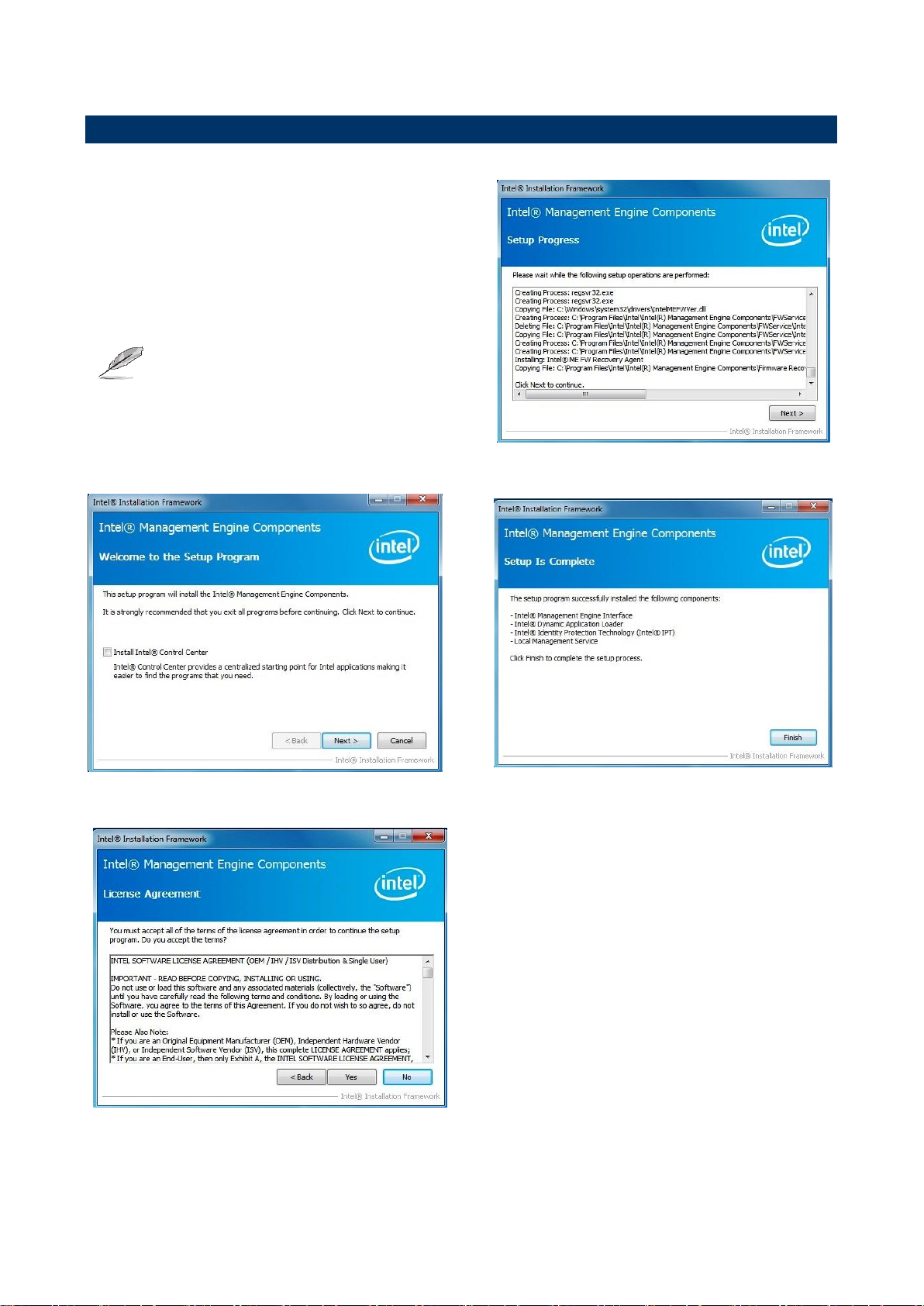
Step 3. Select Install.
Step 1. Select Next to continue installation.
Step 4. Select Finish to complete
Installation.
Step 2. Select Accept to the next step.
4.1 Install Chipset Driver
52 SEAX-H81 User’s Manual
SEAX-H81 User’s Manual
Insert the Supporting DVD-ROM to
DVD-ROM drive, and it should show the index
page of Avalue’s products automatically. If
not, locate Index.htm and choose the product
from the menu left, or link to
\VGA\SEAX-H81_VGA.
Note: The installation procedures and screen
shots in this section are based on
Windows 7 operating system.
Step 3. Select Next to continue
installation.
Step 1. Select Next to start setup.
Step 4. Select Next.
Step 2. Select Yes to the next step.
Step 5. Select Finish to complete
Installation.
4.2 Install VGA Driver
SEAX-H81 User’s Manual 53

SEAX-H81 User’s Manual
Insert the Supporting DVD-ROM to
DVD-ROM drive, and it should show the
index page of Avalue’s products
automatically. If not, locate Index.htm and
choose the product from the menu left, or
link to
\Driver_Gigabit\Realtek\RTL8111E\SEAXH81_LAN.
Note: The installation procedures and
screen shots in this section are
based on Windows 7 operation
system.
Step 3. Click Finish to complete setup.
Step 1. Click Next to Install.
Step 2. Click Install to begin the installation.
4.3 Install LAN Driver (For Realtek 8111E Gigabit Ethernet)
54 SEAX-H81 User’s Manual

SEAX-H81 User’s Manual
Insert the Supporting DVD-ROM to DVD-ROM drive,
and it should show the index page of Avalue’s
products automatically. If not, locate Index.htm and
choose the product from the menu left, or link to
\Driver_Audio\Realtek\ALC662\SEAX-H81_Audio.
Note: The installation procedures and screen shots in
this section are based on Windows 7 operation
system. If the warning message appears while
the installation process, click Continue to go
on.
Step1. Click Next to Install.
Step 2. Select Finish to complete
Installation.
4.4 Install Audio Driver (For Realtek ALC662 HD Audio)
SEAX-H81 User’s Manual 55

SEAX-H81 User’s Manual
Insert the Supporting DVD-ROM to
DVD-ROM drive, and it should show the index
page of Avalue’s products automatically. If
not, locate Index.htm and choose the product
from the menu left, or link to
\Utility\SEAX-H81_USB3.0.
Note: The installation procedures and screen
shots in this section are based on
Windows 7 operating system.
Step 3. Select Next to continue
installation.
Step 1. Select Next to start setup.
Step 4. Select Next to continue
installation.
Step 2. Select Yes to the next step.
Step 5. Select Finish to complete
Installation.
4.5 Install USB3.0 Driver
56 SEAX-H81 User’s Manual
SEAX-H81 User’s Manual
Insert the Supporting DVD-ROM to
DVD-ROM drive, and it should show the index
page of Avalue’s products automatically. If
not, locate Index.htm and choose the product
from the menu left, or link to
\Utility\SEAX-H81_ME.
Note: The installation procedures and screen
shots in this section are based on
Windows 7 operating system.
Step 3. Select Next to continue
installation.
Step 1. Select Next to start setup.
Step 4. Select Finish to complete
Installation.
Step 2. Select Yes to the next step.
4.6 Install ME Driver
SEAX-H81 User’s Manual 57

SEAX-H81 User’s Manual
5. Mechanical Drawing
58 SEAX-H81 User’s Manual

SEAX-H81 User’s Manual
Unit: mm
SEAX-H81 User’s Manual 59

SEAX-H81 User’s Manual
Unit: mm
60 SEAX-H81 User’s Manual
 Loading...