


REV-SA01
SMARC Evaluation Carrier Board
User’s Manual
2nd Ed – 16 October 2014
Part No. E2047VS0101R

REV-SA01 User’s Manual
Content
1. Getting Started ............................................................................................................ 4
1.1 Safety Precautions .................................................................................................... 4
1.2 Packing List ............................................................................................................... 4
1.3 Document Amendment History ................................................................................. 5
1.4 Manual Objectives ..................................................................................................... 6
1.5 System Specifications ............................................................................................... 7
1.6 Architecture Overview—Block Diagram .................................................................... 8
2. Hardware Configuration ............................................................................................. 9
2.1 Product Overview .................................................................................................... 10
2.2 Jumper and Connector List ..................................................................................... 12
2.3 Setting Jumpers & Connectors ............................................................................... 14
2.3.1 Boot Mode selector (SW1) ............................................................................................................. 14
2.3.2 General purpose I/O Power selector (JDIOP1) .............................................................................. 15
2.3.3 Battery connector 1 (JBAT1) .......................................................................................................... 15
2.3.4 Battery connector 2 (JBAT2) .......................................................................................................... 16
2.3.5 General purpose I/O connector (JDIO1) ........................................................................................ 16
2.3.6 SATA Power connector (JSPWR1) ................................................................................................ 17
2.3.7 AMPLIFIER connector (JAMP1) .................................................................................................... 17
2.3.8 LVDS Interface connector (JLVDS1) ............................................................................................. 18
2.3.9 Can Bus connector 1 (JCAN1) ....................................................................................................... 19
2.3.10 Can Bus connector 2 (JCAN2)................................................................................................... 19
2.3.11 LCD inverter connector (JBKL1) ................................................................................................ 20
2.3.12 Line In, MIC connector (JMIC1) ................................................................................................. 20
2.3.13 USB connector (JUSB1) ............................................................................................................ 21
2.3.14 Power connector (PWR1) .......................................................................................................... 21
2.3.15 Serial Port 2 connector (JCOM2) ............................................................................................... 22
3. Linux User Guide ......................................................................................................... 23
3.1 Download Source code for building Ubuntu image file ............................................ 24
3.2 Set up a Linux host for building U-boot & Kernel Image .......................................... 24
3.3 Building up U-boot & Kernel image ................................ ......................................... 24
3.4 Use MfgTool to flash Ubuntu into onboard eMMC .................................................. 26
3.5 Create a bootable SD card with Ubuntu 12.04 file system ...................................... 29
3.6 Bootloader settings for booting from SD card ......................................................... 31
3.7 Bootloader settings for booting from onboard eMMC .............................................. 33
3.8 Display output application of IMX6 .......................................................................... 35
3.9 Download Android Source Code for building image file .......................................... 38
2 REV-SA01 User’s Manual

REV-SA01 User’s Manual
3
3.10 Set up for building Android image file ...................................................................... 38
3.11 Building up Andrioid image file ................................ ................................................ 39
3.12 Use MfgTool to flash Android into onboard eMMC.................................................. 41
REV-SA01 User’s Manual
REV-SA01 User’s Manual
1. Getting Started
1.1 Safety Precautions
Warning!
Always completely disconnect the power cord from your
chassis whenever you work with the hardware. Do not
make connections while the power is on. Sensitive
electronic components can be damaged by sudden power
surges. Only experienced electronics personnel should
open the PC chassis.
Caution!
Always ground yourself to remove any static charge before
touching the CPU card. Modern electronic devices are very
sensitive to static electric charges. As a safety precaution,
use a grounding wrist strap at all times. Place all electronic
components in a static-dissipative surface or static-shielded
bag when they are not in the chassis.
Always note that improper disassembling action could cause damage to the
motherboard. We suggest not removing the heatsink without correct
instructions in any circumstance. If you really have to do this, please contact
us for further support.
1.2 Packing List
Before you begin installing your single board, please make sure that the
following materials have been shipped:
1 x REV-SA01 Micro Module
1 x Quick Installation Guide for REV-SA01
4 REV-SA01 User’s Manual

REV-SA01 User’s Manual
5
Revision
Date
By
Comment
1st
December 2013
Avalue
Initial Release
2nd
October 2014
Avalue
Update Linux User Guide
1.3 Document Amendment History
REV-SA01 User’s Manual

REV-SA01 User’s Manual
1.4 Manual Objectives
This manual describes in details Avalue Technology REV-SA01 Single Board.
We have tried to include as much information as possible but we have not duplicated
information that is provided in the standard IBM Technical References, unless it proved to
be necessary to aid in the understanding of this board.
We strongly recommend that you study this manual carefully before attempting to set up
REV-SA01 series or change the standard configurations. Whilst all the necessary
information is available in this manual we would recommend that unless you are confident,
you contact your supplier for guidance.
Please be aware that it is possible to create configurations within the CMOS RAM that
make booting impossible. If this should happen, clear the CMOS settings, (see the
description of the Jumper Settings for details).
If you have any suggestions or find any errors regarding this manual and want to inform us
of these, please contact our Customer Service department with the relevant details.
6 REV-SA01 User’s Manual

REV-SA01 User’s Manual
7
System
SMARC CPU Module socket: Accepts 82mm x 50mm SMARC Modules
Edge conn
DB9 x 1
DB15 x 1
HDMI x 1
Mini-USB x 1
USB Type A x 2
RJ45 x 2
SD Socket x 1
Backlight conn
5V, GND, ENBKL, VR, PWM
LVDS connector
Hirose DF13-40DS-1.25, support 1 x 18/24bit LVDS
HDMI
HDMI connector
VGA
By Chrontel CH7055 (convert 24bit TTL signal to VGA)
CAN BUS
CAN BUS connector x 2 (JST PHR-4) (CAN PHY TJA1041)
GPIO
10bit GPIO(pin header)
Audio
connector
Speaker out (L & R)
USB
USB Type A double deck x 1
USB signal for mPCIe (x1)
USB 2.0 pin header (x1)
Mini USB connector for USB OTG
SATA
SATA connector x 1, 2pin wafer with 5V, 1A for SATA power
CAN Bus
CAN bus pin header x 2
PCIe
mPCIe socket x 1 (with PCIe x 1 & USB2.0 & USIM signal)
Ethernet
RJ45 connector for GBE (with LED)
2nd Ethernet
From RTL8111E
Camera
Connector
Camera connector with CSI-2 signals + I2C + GPIOx2 + 3.3V or 5V
Audio Codec
WM8962, Line out, MIC in, Speaker out
RTC battery
CR2032, RTC chip is ISL1208
Boot select
8 pin 2.0mm jumper
SD Socket
SD Socket, support SDHC
G-Sensor
MMA8451Q
LED
Power on LED
1.5 System Specifications
REV-SA01 User’s Manual
REV-SA01 User’s Manual
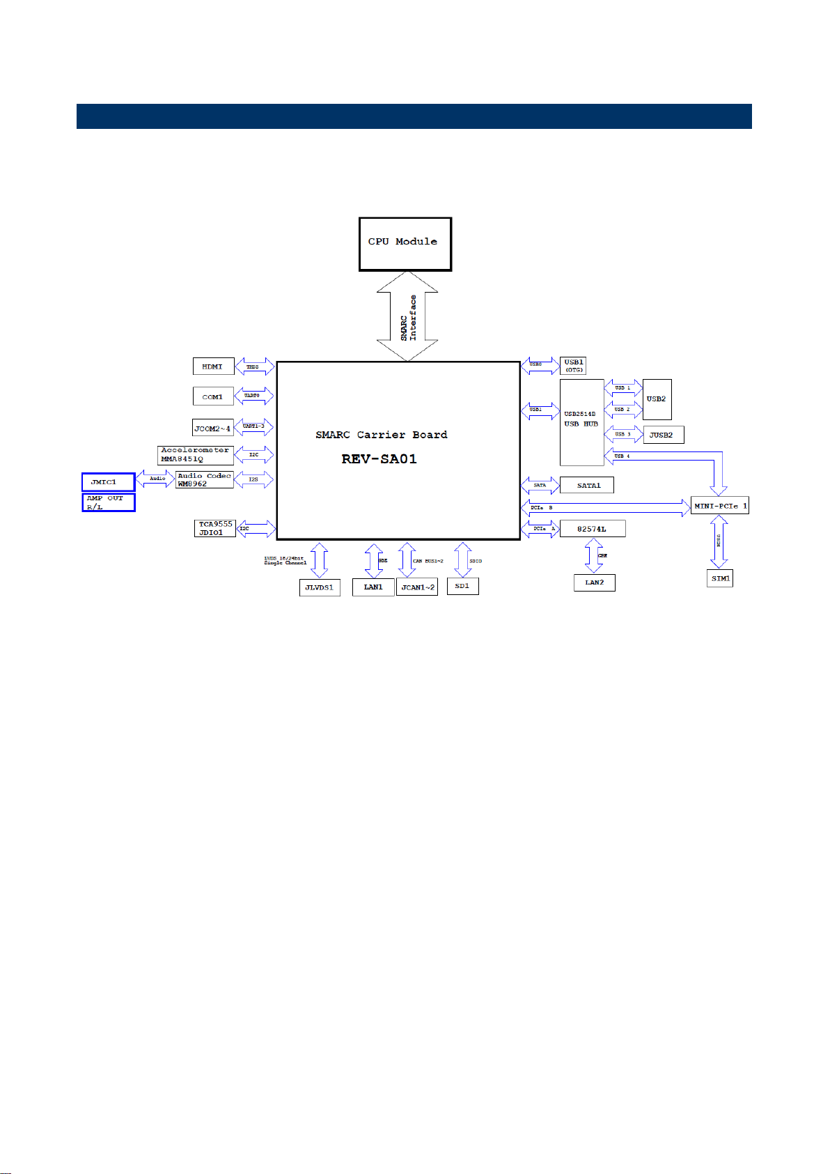
1.6 Architecture Overview—Block Diagram
The following block diagram shows the architecture and main components of REV-SA01.
8 REV-SA01 User’s Manual

REV-SA01 User’s Manual
9
2. Hardware
Configuration
REV-SA01 User’s Manual
REV-SA01 User’s Manual
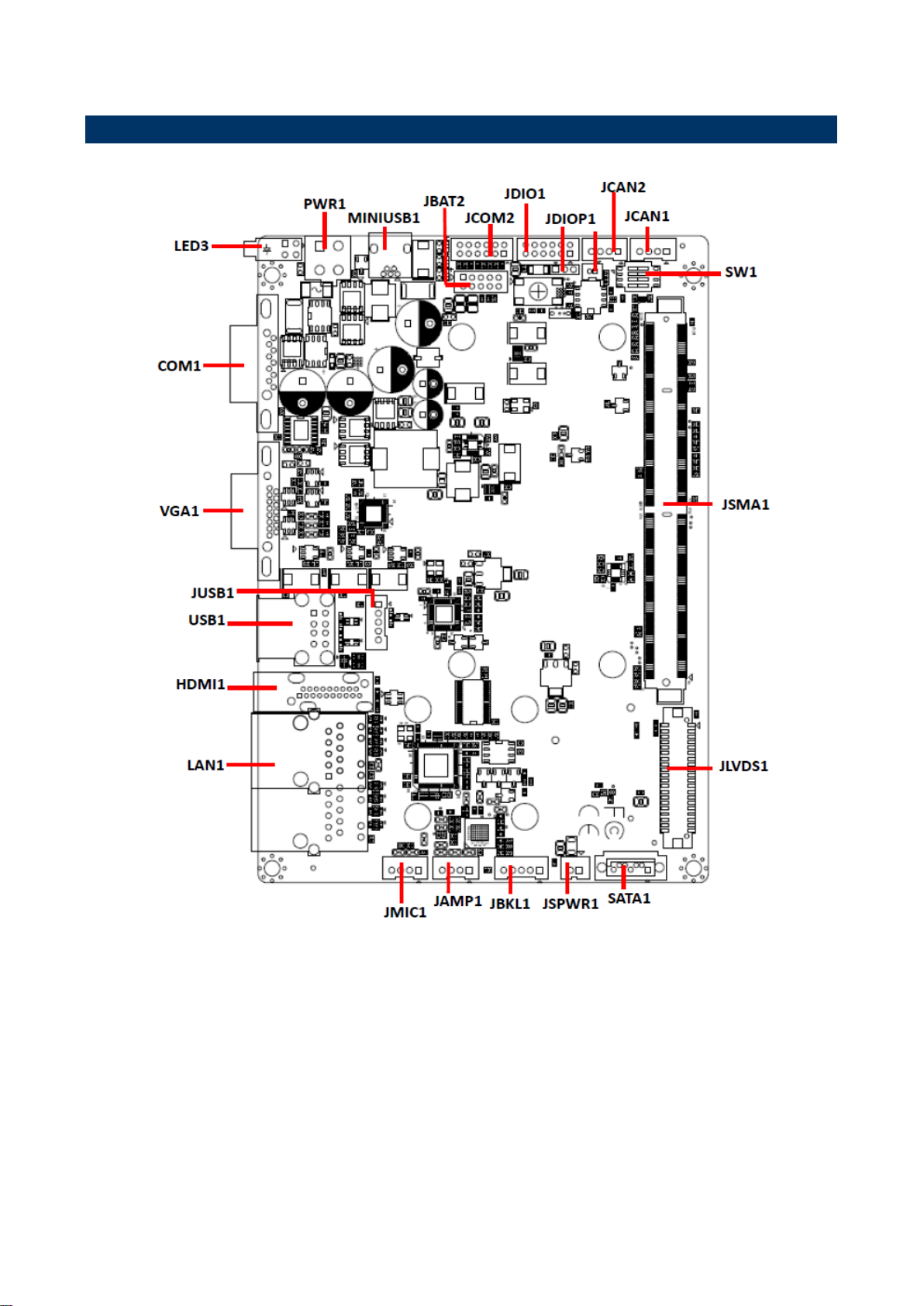
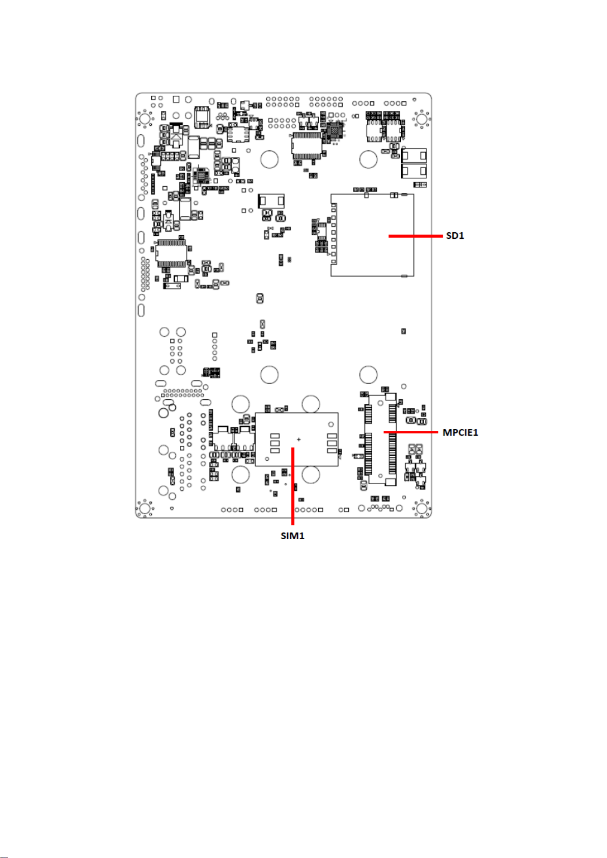
2.1 Product Overview
10 REV-SA01 User’s Manual
REV-SA01 User’s Manual
11
REV-SA01 User’s Manual
REV-SA01 User’s Manual
Jumpers
Label
Function
Note
SW1
Boot Mode selector
DIP Switch 4P
JDIOP1
General purpose I/O Power selector
3 x 1 header, pitch 2.00mm
Connectors
Label
Function
Note
JBAT1
Battery connector 1
2 x 1 wafer, pitch 1.25mm
JBAT2
Battery connector 2
2 x 5 wafer, pitch 2.00mm
JDIO1
General purpose I/O connector
2 x 6 wafer, pitch 2.00mm
JCAN1/2
Can Bus connector 1/2
4 x 1 wafer, pitch 2.00mm
JSMA1
Smart Mobility ARChitecture slot
SATA1
Serial ATA connector 1
JBKL1
LCD inverter connector
5 x 1 wafer, pitch 2.00mm
2.2 Jumper and Connector List
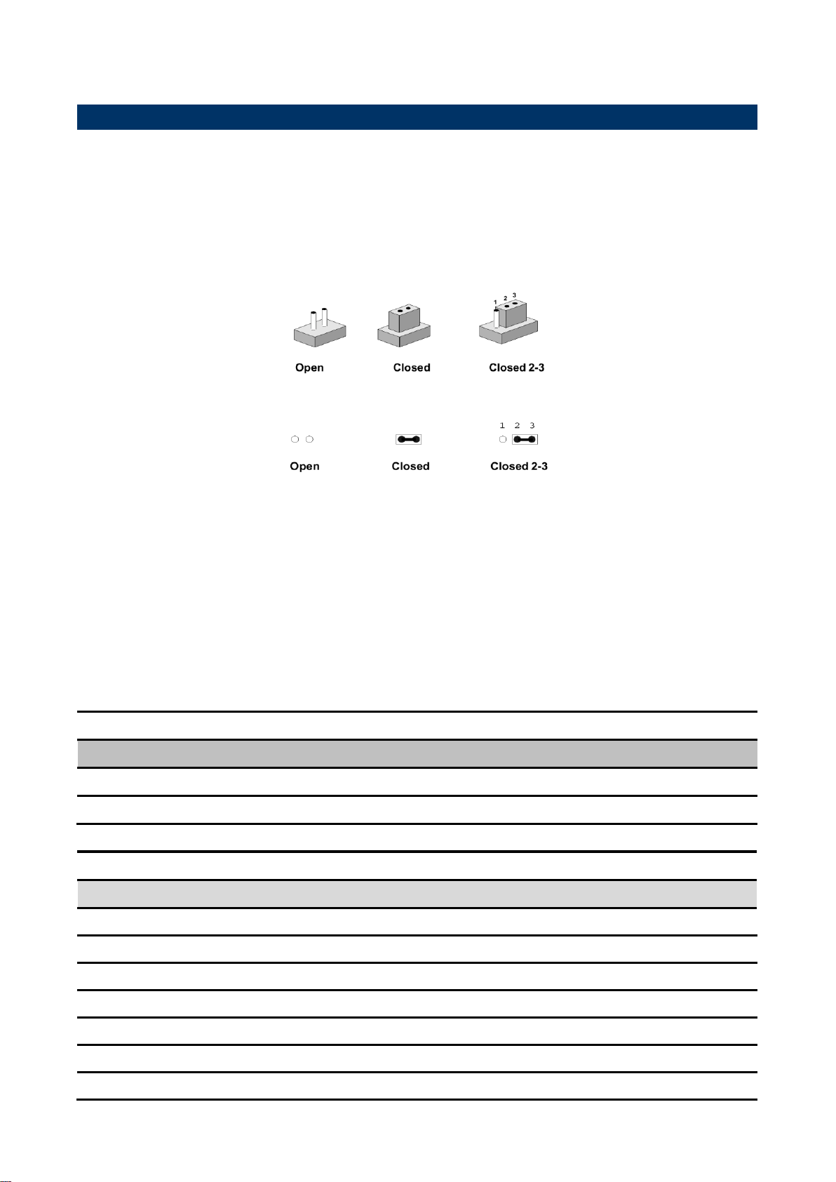
You can configure your board to match the needs of your application by setting jumpers. A
jumper is the simplest kind of electric switch.
It consists of two metal pins and a small metal clip (often protected by a plastic cover) that
slides over the pins to connect them. To “close” a jumper you connect the pins with the clip.
To “open” a jumper you remove the clip. Sometimes a jumper will have three pins, labeled 1,
2, and 3. In this case, you would connect either two pins.
The jumper settings are schematically depicted in this manual as follows:
A pair of needle-nose pliers may be helpful when working with jumpers.
Connectors on the board are linked to external devices such as hard disk drives, a
keyboard, or floppy drives. In addition, the board has a number of jumpers that allow you to
configure your system to suit your application.
If you have any doubts about the best hardware configuration for your application, contact
your local distributor or sales representative before you make any changes.
The following tables list the function of each of the board’s jumpers and connectors.
12 REV-SA01 User’s Manual

REV-SA01 User’s Manual
13
JAMP1
AMPLIFIER connector
4 x 1 wafer, pitch 2.00mm
JMIC1
Line In, MIC connector
4 x 1 wafer, pitch 2.00mm
LAN1
RJ-45 Ethernet connector
VGA1
VGA connector
LED3
LED connector
MINIUSB1
Mini USB connector for Boot/Debug
MINI USB-MAB_5P
COM1
Serial Port 1 connector
JCOM2
Serial Port 2 connector
2 x 6 wafer, pitch 2.00mm
HDMI1
HDMI connector
HDMI_19P
JLVDS1
LVDS Interface connector
20 x 2 wafer, pitch 1.25mm
PWR1
Power connector
2 x 2 wafer, pitch 4.20mm
USB1
USB connector
JUSB1
USB connector
5 x 1 wafer, pitch 2.00mm
JSPWR1
SATA Power connector
2 x 1 wafer, pitch 2.00mm
MPCIE1
Mini-PCI connector
SD1
SD Card Slot
SIM1
SIM Card Slot
SDCARD_9H, Push/Push Type
REV-SA01 User’s Manual

REV-SA01 User’s Manual
Signal
PIN
PIN
Signal
GND
1 8 BOOT_SEL0#
GND
2 7 BOOT_SEL1#
GND
3 6 BOOT_SEL2#
GND
4 5 FORCE_RECOV#
Booting from onboard eMMC
Boot from SD card
MFG tool mode mode(burning image file to
onboard eMMC)
2.3 Setting Jumpers & Connectors
2.3.1 Boot Mode selector (SW1)
14 REV-SA01 User’s Manual

REV-SA01 User’s Manual
15
+5V
+3.3V
Signal
PIN
+V_BAT
1
GND
2
2.3.2 General purpose I/O Power selector (JDIOP1)
2.3.3 Battery connector 1 (JBAT1)
REV-SA01 User’s Manual

REV-SA01 User’s Manual
Signal
PIN
PIN
Signal
+V_BATTERY
1 2 +V_BATTERY
+V_BATTERY
3 4 GND
GND
5 6 BAT_DATA
BAT_TS
7 8 BAT_CLK
GND
9
10
GND
Signal
PIN
PIN
Signal
DIO_GP10
1 2 DIO_GP20
DIO_GP11
3 4 DIO_GP21
DIO_GP12
5 6 DIO_GP22
DIO_GP13
7 8 DIO_GP23
SMB_DATA_9555
9
10
SMB_CLK_9555
+VDIO
11
12
GND
2.3.4 Battery connector 2 (JBAT2)
2.3.5 General purpose I/O connector (JDIO1)
16 REV-SA01 User’s Manual

REV-SA01 User’s Manual
17
Signal
PIN
GND
1
+5V
2
Signal
PIN
SPKL_P
1
SPKL_N
2
SPKR_P
3
SPKR_N
4
2.3.6 SATA Power connector (JSPWR1)
2.3.7 AMPLIFIER connector (JAMP1)
REV-SA01 User’s Manual

REV-SA01 User’s Manual
Signal
PIN
PIN
Signal
+5V
2 1 +3.3V
+5V
4 3 +3.3V
I2C_LCD_DAT
6 5 I2C_LCD_CK
GND
8 7 GND
LVDS0+
10 9 LVDS1+
LVDS0-
12
11
LVDS1-
GND
14
13
GND
LVDS2+
16
15
LVDS3+
LVDS2-
18
17
LVDS3-
GND
20
19
GND
NC
22
21
NC
NC
24
23
NC
GND
26
25
GND
NC
28
27
NC
NC
30
29
NC
GND
32
31
GND
LVDS_CK+
34
33
NC
LVDS_CK-
36
35
NC
GND
38
37
GND
NC
40
39
NC
2.3.8 LVDS Interface connector (JLVDS1)
18 REV-SA01 User’s Manual

REV-SA01 User’s Manual
19
Signal
PIN
CAN0_H
1
GND
2
CAN0_L
3
GND
4
Signal
PIN
CAN1_H
1
GND
2
CAN1_L
3
GND
4
2.3.9 Can Bus connector 1 (JCAN1)
2.3.10 Can Bus connector 2 (JCAN2)
REV-SA01 User’s Manual

REV-SA01 User’s Manual
Signal
PIN
NC
1
GND
2
LCD_BKLT_EN
3
LCD_BKLT_PWM
4
+5V
5
Signal
PIN
MICIN_DET
1
MIC_RAW
2
MICBIAS2_RAW
3
GND
4
2.3.11 LCD inverter connector (JBKL1)
2.3.12 Line In, MIC connector (JMIC1)
20 REV-SA01 User’s Manual

REV-SA01 User’s Manual
21
Signal
PIN
+4V
1
USB3_D-
2
USB3_D+
3
GND
4
GND
5
Signal
PIN
PIN
Signal
RVSP_G
1
2
RVSP_G
+VIN
3 4 +VIN
2.3.13 USB connector (JUSB1)
2.3.14 Power connector (PWR1)
REV-SA01 User’s Manual

REV-SA01 User’s Manual
Signal
PIN
PIN
Signal
RXDD3
1
2
RXDD2
TXDD3
3
4
TXDD2
GND
5
6
GND
CTS3
7
8
RXDD4
RTS3
9
10
TXDD4
GND
11
12
GND
2.3.15 Serial Port 2 connector (JCOM2)
22 REV-SA01 User’s Manual

REV-SA01 User’s Manual
23
3. Linux User Guide
REV-SA01 User’s Manual

REV-SA01 User’s Manual
sudo apt-get install ia32-libs
sudo apt-get install uboot-mkimage
3.1 Download Source code for building Ubuntu image file
Please make a folder for storing the source code first then typing the command below to get
started for the source code download.
$ Sudo apt-get install git
$ git clone guest@202.55.227.57:freescale/core.git -b SMARC
About password, please check with Avalue Sales or PM to get it.
3.2 Set up a Linux host for building U-boot & Kernel Image
We support to compile u-boot & Kernel on Ubuntu 12.04 (64bit version), other version of
Ubuntu is not currently supported and may have built issues.
Install host packages needed by building code. This document assumes you are using
Ubuntu. Not a requirement, but the packages may be named differently and the method of
installing them may be different.
3.3 Building up U-boot & Kernel image
You can follow up the steps below to compile the u-boot & Kernel after downloading the
source code.
1.Please move to folder ”core” then start to compile both the u-boot & Kernel.
..~/$ cd core/
2.Type the command to compile both u-boot & Kernel.
$ make rev-sa01 –j number
(-j number means multi jobs for more efficiant building, you can add it according to your
CPU performance of PC, e.g. mine is ”–j16” as below ).
24 REV-SA01 User’s Manual

REV-SA01 User’s Manual
25
3. You can find the u-boot(u-boot.bin) & Kernel(uImage) under folder ”core” as below after
the compiling is finish.
PS: If you would like to use Mfgtool for flashing image file, you must put the
file u-boot.bin and uImage under “~\Image\smarc” for right detected path.
REV-SA01 User’s Manual

REV-SA01 User’s Manual
3.4 Use MfgTool to flash Ubuntu into onboard eMMC
Manufacturing tool, a successor of ATK, provides a series of new features to power your
mass production work. The features like windows style GUI, multiple devices support,
explicit status monitoring, versatile functionalities and highly flexible architecture make it a
best choice to meet your critical timing, cost and customization requirements.
For using Mfgtool to flash image file into onboard eMMC, please follow up the steps below
1. Please turn on the Pin4 of the DIP switch as below into burning mode of Mfgtool.
2. Power on the mainboard then plug the cable from OTG socket to PC.
3. Click the folder “~\MFG-Tools”, e.g. mine is
D:\ MFG-REV-SA01_Image\MFG-Tools”
4. Click the “MfgLoader.exe”.
26 REV-SA01 User’s Manual

REV-SA01 User’s Manual
27
5. Select the MCU option by name, if the MCU of module board is “i.MX6 Solo”, please
click “MX6DL Linux Update”, and click “Linux-ubuntu” (Ubuntu GUI version) for the OS
of flashing, then click “Run MFG Tool”.
Or the if the MCU of module board is “i.MX6 Quad core”, please click “MX6Q Linux
Update”, and click “Linux-ubuntu” (Ubuntu GUI version) for the OS of flashing,
then click “Run MFG Tool”.
6. The second screen will show up after clicking “Run MFG Tool”, and please check
whether it shows “HID-compliant device” as below, if not, please re-check the cable
connection and DIP switch setting between mainboard and PC.
REV-SA01 User’s Manual

REV-SA01 User’s Manual
7. Click “Start” to flash image file.
8. It will show “Done” after flashing is finish, then click “Stop” and “Exit” to close the screen.
9. You can also get the information from Terminal (debug portCOM1) after flashing is
finish.
28 REV-SA01 User’s Manual

REV-SA01 User’s Manual
29
3.5 Create a bootable SD card with Ubuntu 12.04 file system
Please insert a SD card in the card reader on your Linux host PC
1) Check device node of your SD card by command below.
$cat /proc/partitions (for example, mine is /dev/sdd as below)
Create EXT3 partition for SD card
$ sudo fdisk /dev/sdd
Type the following parameters (each followed by <ENTER>):
d [delete the previous partition]
n [create a new partition]
p [create a primary partition]
1 [the first partition]
20480 [20480x512bytes=10MB, which leaves enough space for the kernel, the
boot loader and its configuration data]
<enter> [using the default value will create a partition that spans to the last
sector of the medium]
w [ this writes the partition table to the medium and fdisk exits]
2) Format new partition in EXT3 format
$sudo umount /dev/sdd1
$sudo mkfs.ext3 /dev/sdd1
3) Install bootloader on SD card by command below.
$ sudo dd if=u-boot-solo.bin(u-boot-quad.bin) of=/dev/sdd bs=1k seek=1 skip=1
conv=fsync
4) Install Linux kernel image on SD card by command below.
$ sudo dd if=uImage of=/dev/sdd bs=1M seek=1 conv=fsync
5) Please find the Ubuntu file system from the path ”CDROM\REV
Image\MFG-REV-SA01_Image\Image\smarc\ ubuntu.tar.bz2” on User`s CD-ROM and
copy it to the partition then follow up the command below.
REV-SA01 User’s Manual

REV-SA01 User’s Manual
$ sudo umount /dev/sdd1
$ sudo mount /dev/sdd1 /mnt
$ cd /mnt
$ sudo tar jxvpf ~/ubuntu.tar.bz2
$ cd
$ sudo umount /dev/sdd1
The Ubuntu file system content is now on the SD card. You can insert it to
mainboard then turn on the DIP switch pin2&3 as below for booting.
30 REV-SA01 User’s Manual

REV-SA01 User’s Manual
31
3.6 Bootloader settings for booting from SD card
1) Please turn on the Pin 2&3 of the DIP switch as below for booting from SD card .
2) Insert SD card on SD socket. Connect RS232 cross over cable from COM1 of
mianboard to COM port of Host PC.
3) Run hyper terminal program on Host PC (teraterm on Windows or minicom on Linux)
4) Power on mainboard and press ”space” key to get into bootloader menu.
5) Setup boot device
SMARC U-Boot > print
REV-SA01 User’s Manual

REV-SA01 User’s Manual
6) Set boot device as below
SMARC U-Boot >setenv linux_cmd ‘setenv bootargs ${linux_bootargs};mmc dev
1;mmc read ${loadaddr} 0x800 0x3000;bootm’
SMARC U-Boot > setenv linux_bootargs 'console=tty0 console=ttymxc0,115200
root=/dev/mmcblk1p1 rootwait rw'
SMARC U-Boot> saveenv
SMARC U-Boot> boot
32 REV-SA01 User’s Manual

REV-SA01 User’s Manual
33
3.7 Bootloader settings for booting from onboard eMMC
1) Please turn on the Pin 1 of the DIP switch as below for booting from onboard eMMC.
2) Insert SD card on SD socket. Connect RS232 cross over cable from COM1 of
mianboard to COM port of Host PC.
3) Run hyper terminal program on Host PC (teraterm on Windows or minicom on Linux)
4) Power on mainboard and press ”space” key to get into bootloader menu.
5) Setup boot device
SMARC U-Boot > print
6) Set boot device as below
SMARC U-Boot >setenv linux_cmd ‘setenv bootargs ${linux_bootargs};mmc dev
3;mmc read ${loadaddr} 0x800 0x3000;bootm’
REV-SA01 User’s Manual

REV-SA01 User’s Manual
SMARC U-Boot > setenv linux_bootargs 'console=tty0 console=ttymxc0,115200
root=/dev/mmcblk0p1 rootwait rw'
SMARC U-Boot> saveenv
SMARC U-Boot> boot
34 REV-SA01 User’s Manual

REV-SA01 User’s Manual
35
3.8 Display output application of IMX6
This section describes how to setup the display output for LVDS, HDMI, VGA of IMX6
module.
1. You can find the file of resolution setup of LVDS&VGA under the
directory ”..~/core/kernel/drivers/video/mxc”, for LVDS is ”ldb.c”, and for VGA is ”
mxc_lcdif.c”.
”ldb.c” ”mxc_lcdif.c”
2. You need to fill the resolution parameter(.mode_str) on the file ”rev_sa01.c”
under ”~/core/kernel/arch/arm/mach-mx6/smarc/”, and the code of First Display is
alway in the upper block.
REV-SA01 User’s Manual

REV-SA01 User’s Manual
3. Finally, you should fill the parameter for booting on the file ”mx6_smarc.h” under the
directory ”~/core/u-boot/include/configs/”.
Please add ”video=mxcfb0:dev=display name” on the column 132
"rootwait rw \0" to enable display output function when booting.
4. Please refer ch1.3 to re-build the u-boot &Kernel binary file for booting.
Note: If you need to use double display output in Ubuntu, you should setup the ”
rev_sa01.c” file first then add the content ”video=mxcfb0:dev=first display name
36 REV-SA01 User’s Manual

REV-SA01 User’s Manual
37
video=mxcfb1:dev=second display neme” to mx6_smarc.h, but for this application, you
also need to write a program for controling the second diplay first or the second display
will not enable after you follow up all the setting above.
REV-SA01 User’s Manual

REV-SA01 User’s Manual
3.9 Download Android Source Code for building image file
Please make a folder for storing the source code first then typing the command below
to get started for the source code download.
$ sudo apt-get install git
$ git clone guest@202.55.227.57:freescale/imx6/Android.git -b 4.4.2-SMARC
About password, please check with Avalue Sales or PM to get it.
3.10 Set up for building Android image file
We support to compile u-boot & Kernel on Ubuntu 12.04 (64bit version), other version of
Ubuntu is not currently supported and may have built issues.
Install host packages needed by building code. This document assumes you are using
Ubuntu. Not a requirement, but the packages may be named differently and the method of
installing them may be different.
1) Please follow up the commands below to install ”Oracle JDK6.0” first for building up
Android image file.
$ sudo apt-get install python-software-properties
$ sudo add-apt-repository ppa:webupd8team/java
$ sudo apt-get update
$ sudo apt-get install oracle-java6-installer
2) Please follow up the commands below to install the necessary package for build image
file.
$ sudo apt-get install git-core gnupg flex bison gperf build-essential \
zip curl libc6-dev libncurses5-dev x11proto-core-dev \
libx11-dev:i386 libreadline6-dev:i386 \
libgl1-mesa-dev g++-multilib mingw32 openjdk-6-jdk tofrodos \
python-markdown libxml2-utils xsltproc zlib1g-dev:i386 \
ia32-libs u-boot-tools minicom lib32ncurses5-dev \
38 REV-SA01 User’s Manual

REV-SA01 User’s Manual
39
3.11 Building up Andrioid image file
You can follow up the steps below to compile Android image file after download the source
code.
1. Please move to the folder ”Android” then start to compile image file.
2. Type the command to compile image file.
$ ./run.sh –j16
(-j number means multi jobs for more efficiant building, you can add it according to
your CPU performance of PC, e.g. mine is ”–j16” as below ).
3. You can find the finished image file(u-boot-6q.bin, u-boot-6solo.bin, system.img,
recover.img, boot.img) as below after compiling on the directory
~/Android/out/target/product/smarc.
REV-SA01 User’s Manual

REV-SA01 User’s Manual
PS: If you would like to use Mfgtool for flashing image file, you must put all the
files u-boot-6q.bin, u-boot-6solo.bin, system.img, recover.img, boot.img under
“~\Image\smarc\android” for right detected path.
40 REV-SA01 User’s Manual

REV-SA01 User’s Manual
41
3.12 Use MfgTool to flash Android into onboard eMMC
Manufacturing tool, a successor of ATK, provides a series of new features to power your
mass production work. The features like windows style GUI, multiple devices support,
explicit status monitoring, versatile functionalities and highly flexible architecture make it a
best choice to meet your critical timing, cost and customization requirements.
For using Mfgtool to flash image file into onboard eMMC, please follow up the steps below
1) Please turn on the Pin4 of the DIP switch as below into burning mode of Mfgtool.
2) Power on the mainboard then plug the cable from OTG socket to PC.
3) Select the right folder by MCU name, if the MCU of module board is “i.MX6 Solo”,
please click the folder “~\ MX6DL-IMX6” to flash image file, e.g. mine is D:\
MFG-REV-SA01_Image\MX6DL-IMX6”
On the other hand, if the MCU of module board is “i.MX6 Quad core”, please click the
folder “~\ MX6Q-IMX6” to flash image file, e.g. mine is
D:\ MFG-REV-SA01_Image\ MX6Q-IMX6”
REV-SA01 User’s Manual

REV-SA01 User’s Manual
4) Click “MfgTool2.exe” to flash image file into smarc module.
5) Click “Start” to flash image file.
6) It will show “Done” after flashing is finish, then click “Stop” and “Exit” to close the screen.
42 REV-SA01 User’s Manual

REV-SA01 User’s Manual
43
7) You can also get the information from Terminal (debug portCOM1) after flashing is
finish.
REV-SA01 User’s Manual
 Loading...