

Page 1
PPC 1725/1727 Series
Fanless 17” SXGA TFT Multifunctional Plastic Panel PC
Quick Reference Guide
1st Ed – 19 March 2013
Copyright Notice
Copyright © 2013 Avalue Technology Inc., ALL RIGHTS RESERVED.
Part No. E2017P172A0R
Page 2

PPC-1725/1727 Series
Contents
1. Getting Started ............................................................................................................ 3
1.1 Safety Precautions ................................................................................................ 3
1.2 Packing List ........................................................................................................... 3
1.3 System Specifications ........................................................................................... 4
1.4 System Overview ................................................................................................... 6
1.4.1 Front View .................................................................................................................................... 6
1.4.2 Rear View ..................................................................................................................................... 6
1.5 System Dimensions ............................................................................................... 8
1.5.1 PPC-1725..................................................................................................................................... 8
1.5.2 PPC-1727..................................................................................................................................... 9
2. Hardware Configuration ........................................................................................... 10
2.1 PPC-1725/1727 Series connector mapping ........................................................ 11
2.1.1 Serial Port 1 connector (COM1)................................................................................................. 11
2.2 Installing Hard Disk & Memory ............................................................................ 12
2 PPC-1725/1727 Series Quick Reference Guide
Page 3
Quick Reference Guide
3
1. Getting Started
1.1 Safety Precautions
Warning!
Always completely disconnect the power cord from your
chassis whenever you work with the hardware. Do not
make connections while the power is on. Sensitive
electronic components can be damaged by sudden power
surges. Only experienced electronics personnel should
open the PC chassis.
Caution!
Always ground yourself to remove any static charge before
touching the CPU card. Modern electronic devices are very
sensitive to static electric charges. As a safety precaution,
use a grounding wrist strap at all times. Place all electronic
components in a static-dissipative surface or static-shielded
bag when they are not in the chassis.
1.2 Packing List
1 x PPC-1725/1727 Series Panel PC
1 x CD/DVD-ROM contains the followings:
— Ethernet drivers and utilities
— VGA drivers and utilities
— Audio drivers and utilities
— Wi-Fi drivers and utilities
— Touch controller drivers and utilities
— Chipset drivers and utilities
1 x packing set includes the followings:
— 1 x power cord
— 1 x AC/DC adapter 12V/5A 60W
PPC-1725/1727 Series Quick Reference Guide
Page 4
PPC-1725/1727 Series
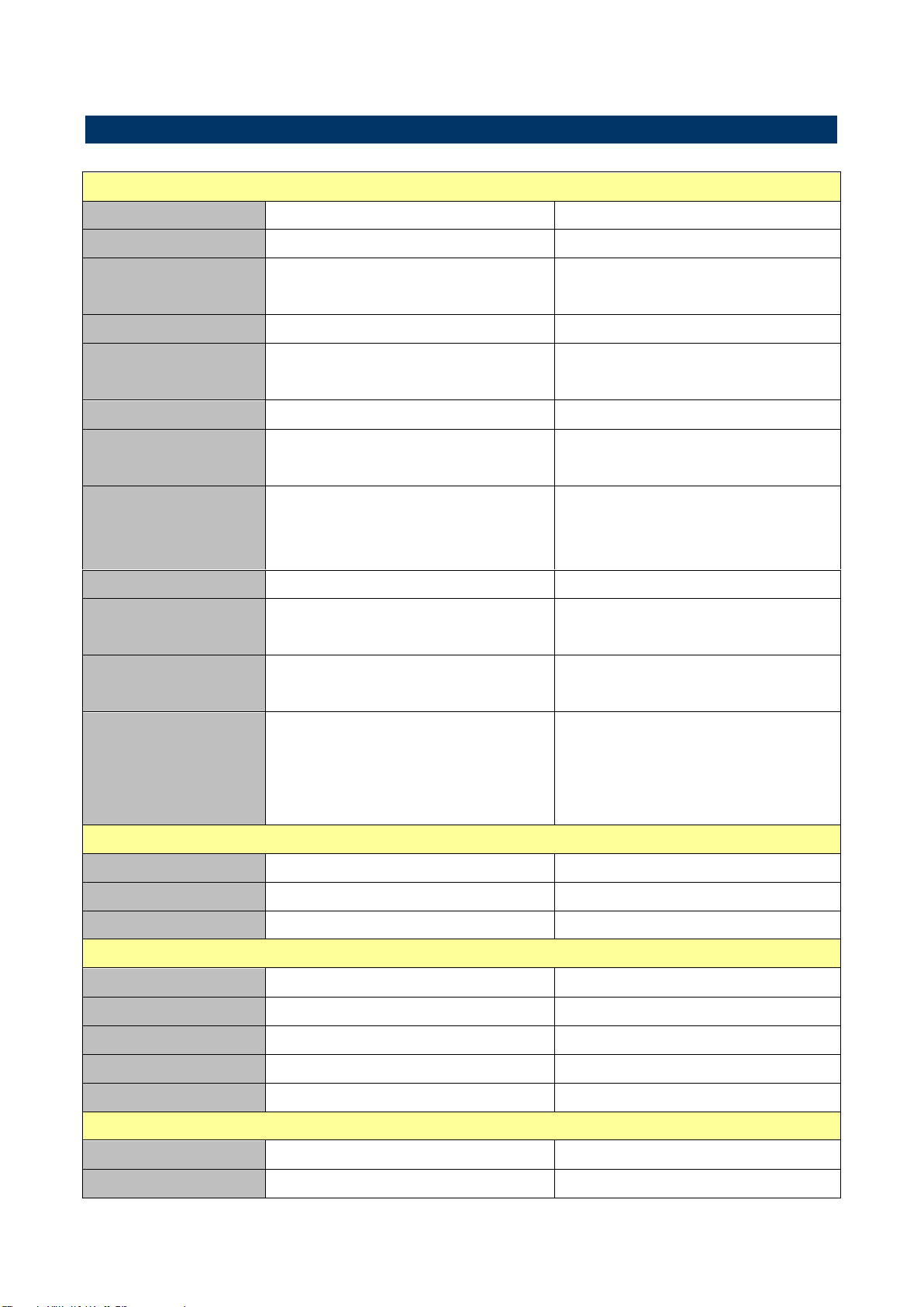
Component
Model
PPC-1725
PPC-1727
Mother Board
EBM-PNV
EBM-CDV
CPU
Onboard Intel® Atom™ D525 Dual
Core 1.8GHz CPU
Onboard Intel® Atom™ D2550
1.86GHz CPU
CPU Cooler (Type)
Fanless Heatsink
Fanless Heatsink
Memory
One 204-pin SODIMM Supports Up
to 4GB DDR3 800MHz SDRAM
One 204-pin SODIMM Supports Up
to 4GB DDR3 1066MHz SDRAM
Audio Chipset
RealTek ALC888-VC2-GR
RealTek ALC892-GR
System Power
Requirement
+12V ~ +28V DC Power Input
+12V ~ +28V DC Power Input
Adapter
Input: 100 ~ 250Vdc/ 47 ~ 63Hz
Output: 60W Adapter (12V @ 5A
Adapter)
Input: 100 ~ 250Vdc/ 47 ~ 63Hz
Output: 60W Adapter (12V @ 5A
Adapter)
Speaker
8Ω 2W*2
8Ω 2W*2
Camera
Optional 2.0M Pixel Camera with
Microphone
Optional 2.0M Pixel Camera with
Microphone
Wireless LAN
Optional USB or Mini PCIe WiFi Module
Optional USB or Mini PCIe WiFi
Module
Operating System
Windows 7
Windows Embedded Standard 7
Windows Embedded POSReady 7
Windows 7 For Embedded System
Windows 7
Windows Embedded Standard 7
Windows Embedded POSReady 7
Windows 7 For Embedded System
Storage
Hard Disk Drive
2.5” HDD
2.5” HDD
Solid State Drive
2.5” SSD
2.5” SSD
Other Storage Device
Type I/II CF
Type I/II CF
Panel
LCD Panel
17" SXGA TFT LCD 1280 x 1024
17" SXGA TFT LCD 1280 x 1024
LCD Control Board
Built-in
Built-in
B/L Inverter/Converter
Built-in
Built-in
Touch Screen
5-wire Resistive
5-wire Resistive
Touch Controller
Onboard Touch EETI
Onboard Touch EETI
External I/O
PS/2 KB & Mouse
1 x PS/2 KB & MS
1 x PS/2 KB & MS
Serial Port
2 x COM D-sub 9 pin RS-232 (1 FOR
2 x COM D-sub 9 pin RS-232 (1 FOR
1.3 System Specifications
4 PPC-1725/1727 Series Quick Reference Guide
Page 5

Quick Reference Guide
5
optional)
optional)
USB Port
3 x USB (1 for Optional)
3 x USB (1 for Optional)
Video Port
1 x VGA D-sub 15 pin
1 x HDMI
Audio Port
1 x Line out
1 x Line out
LAN Port
2 x RJ-45 (1 For Optional)
2 x RJ-45 (1 For Optional)
Mechanical
Power Type
AT/ATX
AT/ATX
Power Connector
Type
Power switch
Power switch
Dimension
391.5mm x 364.5mm x 59mm
391.5mm x 364.5mm x 59mm
Weight
5.9 Kgs
5.9 Kgs
Color
White + Gray
White + Gray
Fanless
Fanless
Fanless
Reliability
EMI Test
Class A
Class B
Safety
CE FCC
CE FCC
Operating
Temperature
0°C ~ 40°C
0°C ~ 40°C
Operating Humidity
0%~90% relative humidity,
non-condensing
0%~90% relative humidity,
non-condensing
Storage Temperature
-10~50°C
-10~50°C
PPC-1725/1727 Series Quick Reference Guide
Page 6

PPC-1725/1727 Series
1.4 System Overview
1.4.1 Front View
Note: The programmable function keys are available to be programmed by the
user, and they are unable to work unless programmed.
1.4.2 Rear View
PPC-1725
PPC-1727
6 PPC-1725/1727 Series Quick Reference Guide
Page 7

Quick Reference Guide
7
Connectors
Label
Function
Note
USB/COM
USB 2.0 connector
Serial port connector
DB-9 male connector
COM1
Serial port 1 connector
DB-9 male connector
Compact Flash/COM2
CF Type I/II Socket with Ejector
Optional for 2nd COM port
DC IN
DC Power-in connector
HDD
HDD LED
LAN1
RJ-45 Ethernet connector 1
KB/MS/LAN2
PS/2 connector
Optional 2nd LAN
LINE OUT
Line-out audio jack
PWR
Power LED
RESET
Reset button
USB
USB 2.0 connector
VGA
VGA connector
only PPC-1725
HDMI
HDMI connector
only PPC-1727
PPC-1725/1727 Series Quick Reference Guide
Page 8

PPC-1725/1727 Series
(Unit: mm)
1.5 System Dimensions
1.5.1 PPC-1725
8 PPC-1725/1727 Series Quick Reference Guide
Page 9

9
(Unit: mm)
1.5.2 PPC-1727
Quick Reference Guide
PPC-1725/1727 Series Quick Reference Guide
Page 10

PPC-1725/1727 Series
2. Hardware
Configuration
Please refer to EBM-PNV, EBM-CDV Quick Installation Guide or User’s
Manual.
Note: If you need more information, please visit our website:
http://www.avalue.com.tw
10 PPC-1725/1727 Series Quick Reference Guide
Page 11

11
In RS-232 Mode
Signal
PIN
PIN
Signal
DCD1
1 2 RxD1
TxD1
3 4 DTR1
GND
5 6 DSR1
RTS1
7 8 CTS1
RI1
9 NC
In RS-422 Mode
Signal
PIN
PIN
Signal
TxD1-
1 2 RxD1+
TxD1+
3 4 RxD1-
GND
5 6 NC
NC
7 8 NC
NC
9 NC
In RS-485 Mode
Signal
PIN
PIN
Signal
DATA1-
1 2 NC
DATA1+
3 4 NC
GND
5 6 NC
NC
7 8 NC
NC
9 NC
2.1 PPC-1725/1727 Series connector mapping
2.1.1 Serial Port 1 connector (COM1)
Quick Reference Guide
PPC-1725/1727 Series Quick Reference Guide
Page 12

PPC-1725/1727 Series
Step 1. Unfasten 4 screws from the rear middle side of your panel.
Step 2. Remove the HDD service window.
Step 3. Slide HDD into its bracket until properly seated .
Step 4. Secure HDD by means of 4 screws.
2.2 Installing Hard Disk & Memory
12 PPC-1725/1727 Series Quick Reference Guide
 Loading...