

Page 1

Part No. E201710W3A0R
MPC-10W3
Fanless Intel® Atom™ N270 10”W Multifunctional Touch
Panel PC with Intel® 945GSE + ICH7-M Chipset
Quick Reference Guide
1st Ed – March 2010
Copyright Notice
Copyright © 2010-2011 Avalue Technology Inc., ALL RIGHTS RESERVED.
Page 2

MPC-10W3
2 MPC-10W3 Quick Reference Guide
FCC Statement
THIS DEVICE COMPLIES WITH PART 15 FCC RULES. OPERATION IS
SUBJECT TO THE FOLLOWING TWO CONDITIONS:
(1) THIS DEVICE MAY NOT CAUSE HARMFUL INTERFERENCE.
(2) THIS DEVICE MUST ACCEPT ANY INTERFERENCE RECEIVED INCLUDING
INTERFERENCE THAT MAY CAUSE UNDESIRED OPERATION.
THIS EQUIPMENT HAS BEEN TESTED AND FOUND TO COMPLY WITH THE LIMITS
FOR A CLASS "A" DIGITAL DEVICE, PURSUANT TO PART 15 OF THE FCC RULES.
THESE LIMITS ARE DESIGNED TO PROVIDE REASONABLE PROTECTION AGAINST
HARMFUL INTERFERENCE WHEN THE EQUIPMENT IS OPERATED IN A
COMMERCIAL ENVIRONMENT. THIS EQUIPMENT GENERATES, USES, AND CAN
RADIATE RADIO FREQUENCY ENERGY AND, IF NOT INSTALLED AND USED IN
ACCORDANCE WITH THE INSTRUCTION MANUAL, MAY CAUSE HARMFUL
INTERFERENCE TO RADIO COMMUNICATIONS.
OPERATION OF THIS EQUIPMENT IN A RESIDENTIAL AREA IS LIKELY TO CAUSE
HARMFUL INTERFERENCE IN WHICH CASE THE USER WILL BE REQUIRED TO
CORRECT THE INTERFERENCE AT HIS OWN EXPENSE.
Copyright Notice
Copyright © 2010-2011 Avalue Technology Inc., ALL RIGHTS RESERVED.
No part of this document may be reproduced, copied, translated, or transmitted in any form
or by any means, electronic or mechanical, for any purpose, without the prior written
permission of the original manufacturer.
A Message to the Customer
Avalue Customer Services
Each and every Avalue’s product is built to the most exacting specifications to ensure
reliable performance in the harsh and demanding conditions typical of industrial
environments. Whether your new Avalue device is destined for the laboratory or the factory
floor, you can be assured that your product will provide the reliability and ease of operation
for which the name Avalue has come to be known.
Your satisfaction is our primary concern. Here is a guide to Avalue’s customer services. To
ensure you get the full benefit of our services, please follow the instructions below carefully.
Page 3

Quick Reference Guide
MPC-10W3 Quick Reference Guide
3
Technical Support
We want you to get the maximum performance from your products. So if you run into
technical difficulties, we are here to help. For the most frequently asked questions, you can
easily find answers in your product documentation. These answers are normally a lot more
detailed than the ones we can give over the phone. So please consult the user’s manual
first.
To receive the latest version of the user’s manual; please visit our Web site at:
http://www.avalue.com.tw/
Headquarters and Branch
Avalue Technology Inc.
7F, 228, Lian-cheng Road, Chung Ho City, Taipei, Taiwan
Tel: +886-2-8226-2345 Fax: +886-2-8226-2777
Information: [email protected]
Service: [email protected]
Avalue USA
Avalue Europe
Avalue Technology Inc.
200 Tornillo Way, Suite 210, Tinton Falls,
NJ 07712
Tel: +1-732-578-0200
Fax: +1-732-578-0250
Information: [email protected]
Service: [email protected]
Avalue Europe A/S
Moelledalen 22C, 3140
Aalsgaarde, Denmark
Tel: +45-7025-0310
Fax:+45-4975-5026
Information: [email protected]
Service: [email protected]
BCM Advanced Research
Avalue China
BCM Advanced Research
an Avalue Company
7 Marconi, Irvine, CA92618
Tel: +1-949-470-1888
Fax: +1-949-470-0971
Information: [email protected]
Web: www.bcmcom.com
Avalue Technology Inc.
Room 805, Building 9,No.99 Tianzhou Rd.,
Caohejing Development Area,
Xuhui District, Shanghai
Tel: +86-21-5169-3609
Fax:+86-21-5445-3266
Information: [email protected]
Service: [email protected]
Page 4

MPC-10W3
4 MPC-10W3 Quick Reference Guide
Contents
1. Getting Started ........................................................................................................5
1.1 Safety Precautions....................................................................................................5
1.2 Packing List...............................................................................................................5
1.3 System Specifications...............................................................................................6
1.4 System Overview......................................................................................................8
1.4.1 Top View.................................................................................................................................. 8
1.4.2 Bottom View............................................................................................................................. 8
1.5 System Dimensions ..................................................................................................9
2. Hardware Configuration .......................................................................................10
2.1 Installing CF card and Memory...............................................................................11
Page 5

Quick Reference Guide
MPC-10W3 Quick Reference Guide
5
1. Getting Started
1.1 Safety Precautions
Warning!
Always completely disconnect the power cord from your
chassis whenever you work with the hardware. Do not
make connections while the power is on. Sensitive
electronic components can be damaged by sudden power
surges. Only experienced electronics personnel should
open the PC chassis.
Caution!
Always ground yourself to remove any static charge before
touching the CPU card. Modern electronic devices are very
sensitive to static electric charges. As a safety precaution,
use a grounding wrist strap at all times. Place all electronic
components in a static-dissipative surface or static-shielded
bag when they are not in the chassis.
1.2 Packing List
z 1 x MPC-10W3 Panel PC
z 1 x Quick Reference Guide
z 1 x DVD-ROM contains the followings:
— User’s Manual (this manual in PDF file)
— Ethernet driver and utilities
— VGA drivers and utilities
— Audio drivers and utilities
— Touch Screen Driver
z 1 x Packing set includes the followings:
⎯ 4 x screws (M4 x 4mm) for VESA-mounting
Page 6

MPC-10W3
6 MPC-10W3 Quick Reference Guide
1.3 System Specifications
Panel
Model MPC-10W3
LCD Size
10”W, 17:10
Resolution
1024 x 600
Pixel Pitch
0.21525mm (H) x 0.21525mm (V)
Luminance
250cd/m²
Contrast Ratio
500
Viewing Angle
50(U), 60(D), 70(L), 70(R)
Response Time
25ms
Backlight
LED Backlight
Touch Type (Optional)
5-wires Resistive
Touch Interface
USB
Page 7

Quick Reference Guide
MPC-10W3 Quick Reference Guide
7
System
Board
EBM-945GSE
CPU
Onboard Intel® Atom™ N270 1.6GHz (2.5W)
BIOS Award 8Mbit Flash BIOS
System Chipset Intel® 945GSE + ICH7-M
I/O Chipset ITE 8712F
System Memory
Onboard 1GB DDR2 and one 200-pin DDR2 SODIMM
supports up to 2GB DDR2 400/533 SDRAM (1GB Per Bank)
SSD
One CF socket bi IDE Secondary Slave Channel
supports Type I / II Compact Flash Card.
Watchdog Timer Reset: 1 ~ 65535 sec./min. and 1 min./step
Display Intel® 945GSE GMCH integrated GMA950 graphics
Audio Realtek ALC 655 supports 5.1-CH Audio
Ethernet Dual Realtek RTL8111C Gigabit LAN, supports wake on LAN
External I/O Ports
COM Port
1 x RS-232/422/485
Ethernet Port
2 x RJ-45
VGA / LCD Port
1 x DB-15
Audio Port
Line-out
USB Port
2 x USB 2.0
Speaker
2 x 2W Speaker
Peripheral
Camera
Optional 1.3M Pixels CMOS Sensor PC Camera
Bluetooth
Optional USB Bluetooth Module
Power Supply Unit
Power Input
100 ~ 250Vdc/ 47 ~ 63Hz
Power Output
+12Vdc/ 5A (60W)
Environment & Mechanical
Operating Temperature
0~40°C (32~104°F)
Storage Temperature
-20 to +75°C (-4~167°F)
Relative Humidity
5 ~ 90% @ 40°C (104°F), relative humidity, non-condensing
Size (L x W)
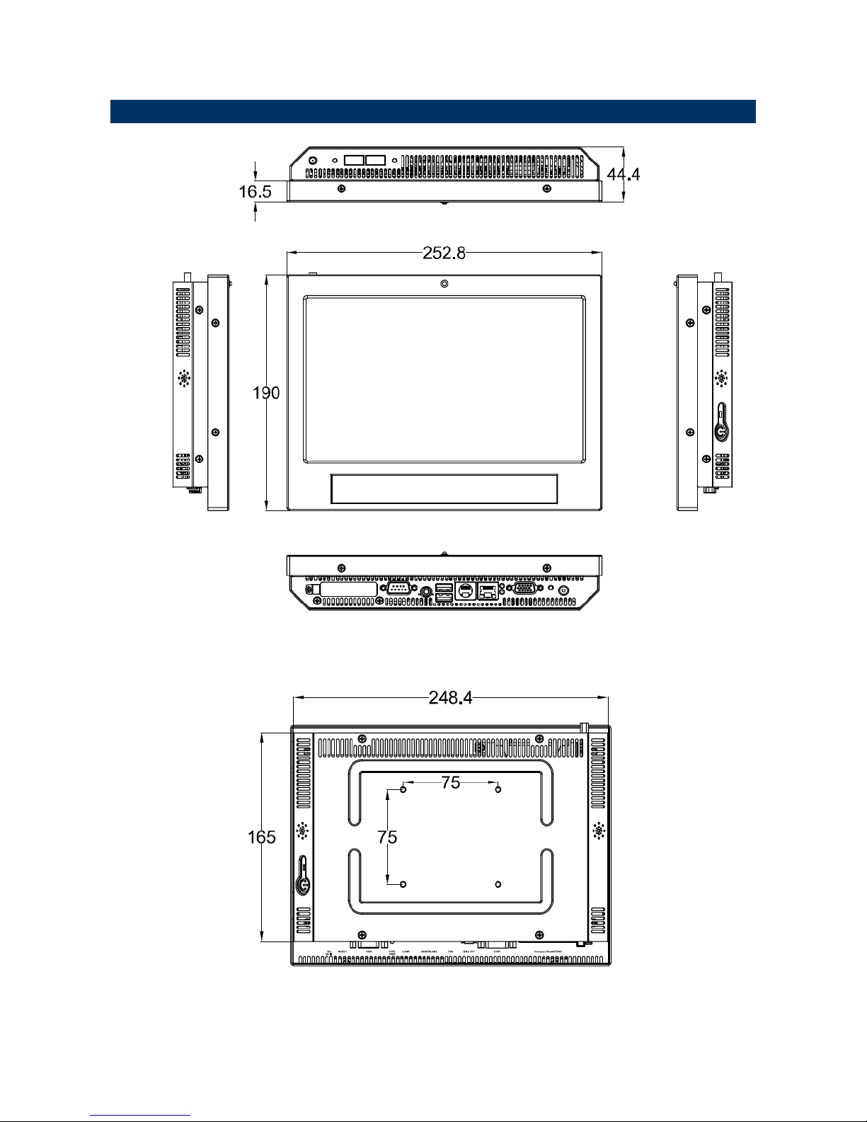
252.8 x 190 x 44.4mm
Weight
1.22Kgs
Mounting
VESA 75 x 75mm, Wall/ Stand
Page 8

MPC-10W3
8 MPC-10W3 Quick Reference Guide
1.4 System Overview
1.4.1 Top View
1.4.2 Bottom View
Connectors
Label Function Note
CF
CF Type I/II Socket with Ejector
COM
Serial port DB-9 male connector
LINE OUT
Line-out audio jack
USB
2 x USB 2.0 connector Dock USB
LAN1
RJ-45 Ethernet connector 1
LAN2
(KB/MS)
RJ-45 Ethernet connector 2
(LAN2 is default, KB/MS is optional)
VGA
CRT connector DB-15 female connector
DC IN
DC Power-in connector
12V DC IN
V
GA
LAN
KB/MS/LAN
USBCOM
LINE OUT
Com
p
act Flash
Page 9
Quick Reference Guide
MPC-10W3 Quick Reference Guide
9
1.5 System Dimensions
Page 10

MPC-10W3
10 MPC-10W3 Quick Reference Guide
2. Hardware
Configuration
Note: If you need more information, please visit our website:
http://www.avalue.com.tw
Page 11

Quick Reference Guide
MPC-10W3 Quick Reference Guide
11
2.1 Installing CF card and Memory
Step1. Unfasten 8 screws from the case then take off the top chassis.
Step2. Insert the SODIMM into the memory socket.
Step3. Place back the chassis with 8 screws locked.
Page 12
MPC-10W3
12 MPC-10W3 Quick Reference Guide
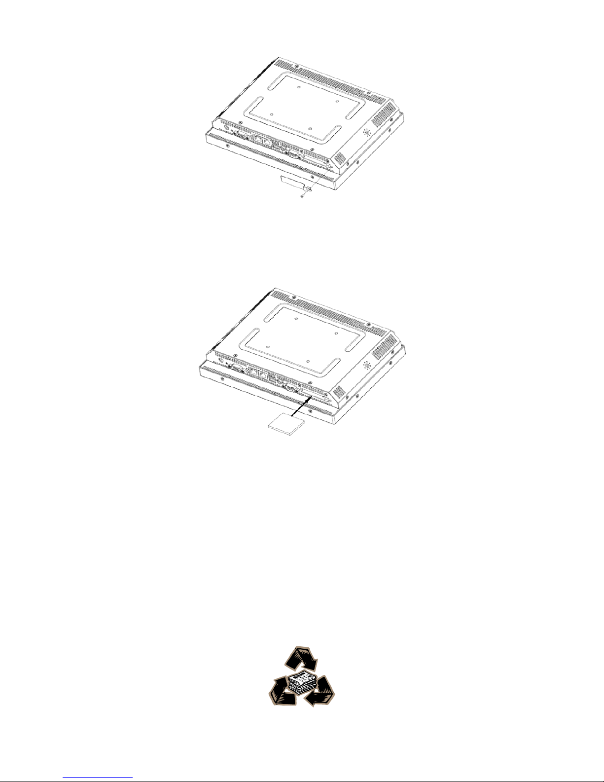
Step4. Unfasten the screws from the CF Socket cover.
Step5. Insert the Compact Flash Card into the CF Socket
 Loading...