


FPC-08R1
8" SVGA TFT RISC Panel PC with FreeScale IMX51
Quick Reference Guide
1st Ed –1 April 2013
Copyright Notice
Copyright 2013 Avalue Technology Inc., ALL RIGHTS RESERVED.
Part No. E201708R1A0R

FPC-08R1
CONTENT
1. Getting Started ............................................................................................................ 3
1.1 Safety Precautions ................................................................................................ 3
1.2 Packing List ........................................................................................................... 3
1.3 System Specifications ........................................................................................... 4
1.4 System Overview ................................................................................................... 5
1.4.1 Front & Top View ......................................................................................................................... 5
1.4.2 Right Side View ............................................................................................................................ 5
1.4.3 Left Side View .............................................................................................................................. 6
1.4.4 Rear View ..................................................................................................................................... 6
2. Hardware Configuration ............................................................................................. 7
2.1 Jumper & connector list ......................................................................................... 8
2.2 Jumper & connector settings ................................................................................. 9
2.2.1 Serial port connector (COM) ........................................................................................................ 9
2.2.2 Boot Mode selector .................................................................................................................... 10
2.2.3 DC power-in connector (DC-IN) ................................................................................................. 10
2.2.4 Debug port connector (Debug port) ........................................................................................... 11
2.3 Installing SD Card (FPC-08R1) ........................................................................... 12
2 FPC-08R1 Quick Reference Guide
Quick Reference Guide
3
1. Getting Started
1.1 Safety Precautions
Warning!
Always completely disconnect the power cord from your
chassis whenever you work with the hardware. Do not
make connections while the power is on. Sensitive
electronic components can be damaged by sudden power
surges. Only experienced electronics personnel should
open the PC chassis.
Caution!
Always ground yourself to remove any static charge before
touching the CPU card. Modern electronic devices are very
sensitive to static electric charges. As a safety precaution,
use a grounding wrist strap at all times. Place all electronic
components in a static-dissipative surface or static-shielded
bag when they are not in the chassis.
1.2 Packing List
1 x 8” SVGA TFT RISC Panel PC System.
1 x CD/DVD-ROM contains the followings:
— User’s Manual (this manual in PDF file)
— Win CE & Linux software (bootloader, Kernel, Image, BSP, SDK)
— iMX_AdvancedToolKit
— Mfgtools
1 x Quick Reference Guide
Other major components include the following:
— 1 x Power Adapter(12V/5A)
FPC-08R1 Quick Reference Guide

FPC-08R1
Panel
Model
FPC-08R1-M51
FPC-08R1-M51W
LCD size
8 inch
Display type
SVGA TFT
Resolution
800(R.G.B) x 600
Color
262K
Pixel pitch
0.0675mm(W) x 0.2025mm(H)
Luminance
250cd/m²
Contrast ratio
400
Viewing angle
50(U), 70(D), 70(L), 70(R)
Response time
10 ms
Backlight
LED
Touch Type
4-Wire Resistive
Touch Light Transmission
80%
Integrated Module
Reserved
w/ WiFi Module
System
Board
RSC-IMX51
CPU
Freescale i.MX515 ARM Cortex-A8 800MHz
PMIC
Freescale MC13892AJVL
eMMC
Onboard 4GB eMMC
Memory
Onboard 512MB DDR2 SDRAM
SSD
SD socket support SDHC (eSDHC-2)
Rear Panel I/O
Serial Port
2 x DB9 connectors for 1 x RS-232/ 422/ 485 and 1 x Debug port
USB Host
2 x USB 2.0 connectors (Type A)
USB Client
1 x Mini-USB connector
Fast Ethernet
1 x RJ-45 connector (10/100 Base-TX)
Mechanical & Environmental
Color
Front & Rear panel Black
Power Requirement
+12 VDC Input
Operating Temperature
0°C to 40°C (32°F to 140°F)
Relative Humidity
0%~90% relative humidity, non-condensing
Storage Temperature
-20°C to 60°C
Mounting
Wall/Stand/VESA 75 mm X 75 mm
Dimensions
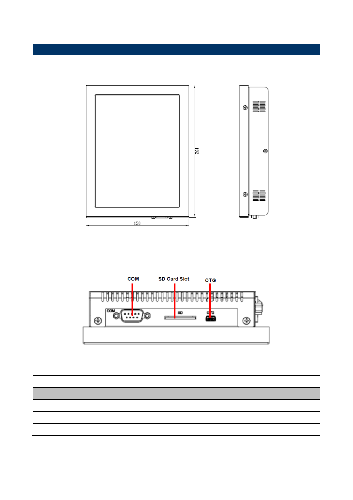
192mm x 150mm x 42.2mm
Weight
0.95Kgs
1.3 System Specifications
4 FPC-08R1 Quick Reference Guide
5
Connectors
Label
Function
Note
SD Card Slot
SD/SDHC card socket
Right side
OTG
USB on The Go connector
Mini USB connector
COM
Serial port connector
DB-9 male connector
1.4 System Overview
1.4.1 Front & Top View
Quick Reference Guide
1.4.2 Right Side View
FPC-08R1 Quick Reference Guide

FPC-08R1
Connectors
Label
Function
Note
DC-IN
+12V DC power-in connector
Debug port
Debug target application
DB-9 male connector
LAN
RJ-45 Fast Ethernet connector
MODE SWITCH
Boot Mode selector
Power S/W
System power switch
RESET
Reset button
USB1~2
USB 2.0 connector 1~2
1.4.3 Left Side View
1.4.4 Rear View
6 FPC-08R1 Quick Reference Guide

7
2. Hardware
Configuration
Jumper and Connector Setting
For advanced information, please refer to:
1- RSC-IMX51 Installation Guide or User’s Manual
2- AUX-MPCIE (Optional) Installation Guide.
Note: If you need more information, please visit our website:
http://www.avalue.com.tw
Quick Reference Guide
FPC-08R1 Quick Reference Guide

FPC-08R1
Connectors
Label
Function
Note
COM
Serial port connector
DB-9 male connector
DC-IN
+12V DC power-in connector
Debug port
Debug target application
DB-9 male connector
LAN
RJ-45 Fast Ethernet connector
MODE SWITCH
Boot Mode selector
OTG
USB on The Go connector
Right side
Power S/W
System power switch
RESET
Reset button
SD Card Slot
SD/SDHC card socket
Right side
USB
USB 2.0 connector 1&2
2.1 Jumper & connector list
8 FPC-08R1 Quick Reference Guide
9
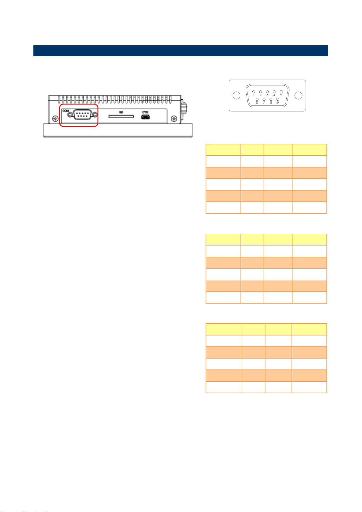
RS232 mode
Signal
Pin
Pin
Signal
NC 1 2
RX
TX 3 4
NC
GND
5 6 NC
RTS
7 8 CTS
NC
9
10
GND
RS422 mode
Signal
Pin
Pin
Signal
TX- 1 2
RX+
TX+ 3 4
RX-
GND
5 6 NC
NC 7 8
NC
NC
9
10
GND
RS485 mode
Signal
Pin
Pin
Signal
DATA-
1
2
NC
DATA+
3 4 NC
GND
5 6 NC
NC
7 8 NC
NC
9
10
GND
2.2 Jumper & connector settings
2.2.1 Serial port connector (COM)
Quick Reference Guide
FPC-08R1 Quick Reference Guide

FPC-08R1
Signal
PIN
PIN
Signal
BMOD1
1
5
+V2D775_BOOT
BMOD0
2 6 BT_SRC[1]
3
7
+V1D8_DIG1
BT_SRC[0]
4
8
Boot from onboard SD
Boot from SD socket
DIP ON ↓
USB OTG mode
DIP ON ↓
Please note:
DIP Switch setting:
0=Off, 1=On
When Position4 is switched On, the system is forced to power On as soon as power is applied. Switch to Off
mode for normal operation.
DC-IN 12V
2.2.2 Boot Mode selector
2.2.3 DC power-in connector (DC-IN)
10 FPC-08R1 Quick Reference Guide

11
Signal
Pin
Pin
Signal
NC
1 2 RX
TX
3 4 NC
GND
5 6 NC
RTS
7 8 CTS
NC
9
10
GND
2.2.4 Debug port connector (Debug port)
Quick Reference Guide
FPC-08R1 Quick Reference Guide

FPC-08R1
Step1. Put SD Card into the SD Card Slot.
2.3 Installing SD Card (FPC-08R1)
12 FPC-08R1 Quick Reference Guide
 Loading...