

Avalue ESM-QM77B User Manual

ESM-QM77B
Intel BGA Type CPU QM77 COM Express Type 6 Module
User’s Manual
1st Ed – 21 January 2013
Notice
This guide is designed for experienced users to perform quick setup of the
system. For detailed information, please always refer to the electronic user's
manual.
Copyright Notice
Copyright 2013 Avalue Technology Inc., ALL RIGHTS RESERVED.
Part No. E2047286600R

ESM-QM77B
FCC Statement
A Message to the Customer
THIS DEVICE COMPLIES WITH PART 15 FCC RULES. OPERATION IS
SUBJECT TO THE FOLLOWING TWO CONDITIONS:
(1) THIS DEVICE MAY NOT CAUSE HARMFUL INTERFERENCE.
(2) THIS DEVICE MUST ACCEPT ANY INTERFERENCE RECEIVED INCLUDING
INTERFERENCE THAT MAY CAUSE UNDESIRED OPERATION.
THIS EQUIPMENT HAS BEEN TESTED AND FOUND TO COMPLY WITH THE LIMITS
FOR A CLASS "A" DIGITAL DEVICE, PURSUANT TO PART 15 OF THE FCC RULES.
THESE LIMITS ARE DESIGNED TO PROVIDE REASONABLE PROTECTION AGAINST
HARMFUL INTERFERENCE WHEN THE EQUIPMENT IS OPERATED IN A
COMMERCIAL ENVIRONMENT. THIS EQUIPMENT GENERATES, USES, AND CAN
RADIATE RADIO FREQUENCY ENERGY AND, IF NOT INSTATLLED AND USED IN
ACCORDANCE WITH THE INSTRUCTION MANUAL, MAY CAUSE HARMFUL
INTERFERENCE TO RADIO COMMUNICATIONS.
OPERATION OF THIS EQUIPMENT IN A RESIDENTIAL AREA IS LIKELY TO CAUSE
HARMFUL INTERFERENCE IN WHICH CASE THE USER WILL BE REQUIRED TO
CORRECT THE INTERFERENCE AT HIS OWN EXPENSE.
Avalue Customer Services
Each and every Avalue’s product is built to the most exacting specifications to ensure
reliable performance in the harsh and demanding conditions typical of industrial
environments. Whether your new Avalue device is destined for the laboratory or the factory
floor, you can be assured that your product will provide the reliability and ease of operation
for which the name Avalue has come to be known.
Your satisfaction is our primary concern. Here is a guide to Avalue’s customer services. To
ensure you get the full benefit of our services, please follow the instructions below carefully.
Technical Support
We want you to get the maximum performance from your products. So if you run into
technical difficulties, we are here to help. For the most frequently asked questions, you can
easily find answers in your product documentation. These answers are normally a lot more
detailed than the ones we can give over the phone. So please consult the user’s manual
first.
To receive the latest version of the user’s manual; please visit our Web site at:
http://www.avalue.com.tw/
2 ESM-QM77B User’s Manual

User’s Manual
3
CONTENT
1. Getting Started ............................................................................................................ 6
1.1 Safety Precautions .................................................................................................... 6
1.2 Packing List ............................................................................................................... 6
1.3 Document Amendment History ................................................................................. 7
1.4 Manual Objectives ..................................................................................................... 8
1.5 System Specifications ............................................................................................... 9
1.6 Architecture Overview—Block Diagram .................................................................. 10
2. Hardware Configuration ........................................................................................... 11
2.1 Product Overview .................................................................................................... 12
2.2 Installation Procedure ............................................................................................. 14
2.2.1 Main Memory .................................................................................................................................. 15
2.3 Connector List ......................................................................................................... 17
2.4 Setting Jumpers & Connectors ............................................................................... 18
2.4.1 AT/ATX mode selector (SW1) ........................................................................................................ 18
2.4.1.1 Signal Description –AT/ATX mode selection ......................................................................... 18
2.4.2 COM Express Connector 1 (CN1A) ............................................................................................... 19
2.4.2.1 Signal Description – COM Express Connector 1 (CN1A) ........................................................... 23
2.4.2.1.1 Audio Signals .................................................................................................................... 23
2.4.2.1.2 Gigabit Ethernet Signals ................................................................................................... 23
2.4.2.1.3 GPIO Signals ..................................................................................................................... 23
2.4.2.1.4 Flat Panel LVDS Signals ................................................................................................... 23
2.4.2.1.5 LPC Signals ....................................................................................................................... 24
2.4.2.1.6 Miscellaneous Signals ....................................................................................................... 24
2.4.2.1.7 PCI Express Signals.......................................................................................................... 24
2.4.2.1.8 Power Signals ................................................................................................................... 25
2.4.2.1.9 Power & System Management Signals ............................................................................. 25
2.4.2.1.10 SATA Signals ................................................................................................................... 26
2.4.2.1.11 VGA Signals ..................................................................................................................... 26
2.4.2.1.12 USB Signals ..................................................................................................................... 26
2.4.3 COM Express Connector 2 (CN1B) ............................................................................................... 27
2.4.3.1 Signal Description – COM Express Connector 2 (CN1B) ........................................................ 31
2.4.3.1.1 USB Signals ...................................................................................................................... 31
2.4.3.1.2 PEG Signals ...................................................................................................................... 31
2.4.3.1.3 DDI Signals ....................................................................................................................... 31
2.5 Intel HD Graphics – 3 Active Displays Support ....................................................... 32
ESM-QM77B User’s Manual

ESM-QM77B
3.BIOS Setup .................................................................................................................... 34
3.1 Introduction ............................................................................................................. 35
3.2 Starting Setup ......................................................................................................... 35
3.3 Using Setup ............................................................................................................ 36
3.4 Getting Help ............................................................................................................ 37
3.5 In Case of Problems ................................................................................................ 37
3.6 BIOS setup ................................................................ ................................ .............. 38
3.6.1 Main Menu ...................................................................................................................................... 38
3.6.1.1 System Language .................................................................................................................. 38
3.6.1.2 System Date .......................................................................................................................... 38
3.6.1.3 System Time .......................................................................................................................... 38
3.6.2 Advanced Menu ............................................................................................................................. 39
3.6.2.1 APCI Settings ........................................................................................................................ 40
3.6.2.2 Trusted Computing ................................................................................................................ 40
3.6.2.3 CPU Configuration ................................................................................................................. 41
3.6.2.4 SATA Configuration ............................................................................................................... 42
3.6.2.5 PCH-FW Configuration .......................................................................................................... 42
3.6.2.6 AMT Configuration ................................................................................................................. 43
3.6.2.7 USB Configuration ................................................................................................................. 44
3.6.2.8 H/W Monitor2 ......................................................................................................................... 45
3.6.2.9 Super IO Configuration .......................................................................................................... 46
3.6.2.9.1 Serial Port 1 Configuration .................................................................................................... 46
3.6.2.9.2 Serial Port 2 Configuration .................................................................................................... 48
3.6.2.9.3 Parallel Port Configuration ..................................................................................................... 49
3.6.2.10 Intel® Smart Connect Technology ........................................................................................ 50
3.6.2.11 CPU PPM Configuration ........................................................................................................ 50
3.6.3 Chipset.......................................................................................................................................... 51
3.6.3.1 PCH-IO Configuration .......................................................................................................... 52
3.6.3.1.1 USB Configuration ............................................................................................................... 53
3.6.3.1.2 PCH Azalia Configuration .................................................................................................... 54
3.6.3.2 System Agent (SA) Configuration ......................................................................................... 55
3.6.3.2.1 Memory Configuration ....................................................................................................... 56
3.6.3.3 Graphics Configuration ........................................................................................................ 56
3.6.4 Boot .............................................................................................................................................. 59
3.6.4.1 CSM parameters ...................................................................................................................... 60
3.6.5 Security ......................................................................................................................................... 61
3.6.6 Save and exit ................................................................................................................................ 62
3.6.6.1 Save Changes and Exit ......................................................................................................... 62
3.6.6.2 Discard Changes and Exit ..................................................................................................... 62
4 ESM-QM77B User’s Manual

User’s Manual
5
3.6.6.3 Save Changes and Reset ...................................................................................................... 63
3.6.6.4 Discard Changes and Reset .................................................................................................. 63
3.6.6.5 Save Changes ........................................................................................................................ 63
3.6.6.6 Discard Changes .................................................................................................................... 63
3.6.6.7 Restore Defaults .................................................................................................................... 63
3.6.6.8 Save as User Defaults ........................................................................................................... 63
3.6.6.9 Restore User Defaults ........................................................................................................... 63
3.6.6.10 Boot Override ....................................................................................................................... 63
3.6.6.11 Launch EFI Shell from filesystem device ............................................................................. 63
4. Drivers Installation....................................................................................................... 64
4.1 Install Chipset Driver (For Intel QM77) .................................................................... 65
4.2 Install Display Driver (For Intel QM77) .................................................................... 66
4.3 Install LAN Driver (For Intel 82579) ......................................................................... 68
4.4 Install USB 3.0 Driver (For Intel QM77) ................................................................... 70
4.5 Install ME Driver (For Intel QM77) ............................................................................. 71
5. Mechanical Drawing .................................................................................................... 73
ESM-QM77B User’s Manual
ESM-QM77B
1. Getting Started
1.1 Safety Precautions
Warning!
Always completely disconnect the power cord from your
chassis whenever you work with the hardware. Do not
make connections while the power is on. Sensitive
electronic components can be damaged by sudden power
surges. Only experienced electronics personnel should
open the PC chassis.
Caution!
Always ground yourself to remove any static charge before
touching the CPU card. Modern electronic devices are very
sensitive to static electric charges. As a safety precaution,
use a grounding wrist strap at all times. Place all electronic
components in a static-dissipative surface or static-shielded
bag when they are not in the chassis.
1.2 Packing List
Before you begin installing your single board, please make sure that the
following materials have been shipped:
1 x ESM-QM77B Intel BGA Type CPU QM77 COM Express Type 6
Module
1 x Quick Installation Guide
1 x DVD-ROM contains the followings:
— User’s Manual (this manual in PDF file)
— Chipset and Ethernet driver
6 ESM-QM77B User’s Manual

7
1.3 Document Amendment History
Revision
Date
By
Comment
1st
January
2013
Avalue
Initial Release
User’s Manual
ESM-QM77B User’s Manual

ESM-QM77B
1.4 Manual Objectives
This manual describes in details Avalue Technology ESM-QM77B Single Board.
We have tried to include as much information as possible but we have not duplicated
information that is provided in the standard IBM Technical References, unless it proved to
be necessary to aid in the understanding of this board.
We strongly recommend that you study this manual carefully before attempting to set up
ESM-QM77B series or change the standard configurations. Whilst all the necessary
information is available in this manual we would recommend that unless you are confident,
you contact your supplier for guidance.
Please be aware that it is possible to create configurations within the CMOS RAM that
make booting impossible. If this should happen, clear the CMOS settings, (see the
description of the Jumper Settings for details).
If you have any suggestions or find any errors regarding this manual and want to inform us
of these, please contact our Customer Service department with the relevant details.
8 ESM-QM77B User’s Manual
9
1.5 System Specifications
System
CPU
On board Intel Core i7/i5/i3/Celeron (FCBGA1023) Processors
BIOS
AMI 64M-bit SPI BIOS
System Chipset
Intel QM77 Chipset
System Memory
Two 204-pin DDR3 SODIMM socket, supports up to 16GB DDR3 1333/1600 SDRAM
Expansion
7 PCIe x1, 1 PCIe x16
I/O
MIO
4 x Serial ATA ports, SMbus
USB
8 x USB 2.0 , 4xUSB 3.0ports
DIO
4-bit GPI, 4-bit GPO
Display
Chipset
Intel QM77 Chipset Integrated
Memory
DVMT 5.0 up to 512MB
Resolution
CRT Mode: 2048 x 1536
LCD/ Simultaneous Mode: 1920 x 1200
LVDS
Dual channel 18/24-bit LVDS
Display Supported
HDMI, DVI, Display Port
Audio
Chipset
Intel QM77 integrated
Interface
Intel High Definition Audio
Ethernet
LAN Chip
Intel 82579LM
Ethernet Interface
10/100/1000 Base-Tx Gigabit Ethernet Compatible
Mechanical &
Environmental
Power
Requirement
+9~ +19V
ACPI
Single power ATX Support S0, S3, S4, S5
ACPI 3.0 Compliant
Power Type
AT/ATX
Operating Temp.
0 to 60C
Storage Temp.
-40~-75°C
Operating
Humidity
0%~90% relative humidity, non-condensing
Size (L x W)
125 mm x 95 mm
Weight
0.44lbs(0.2kg)
User’s Manual
ESM-QM77B User’s Manual
ESM-QM77B
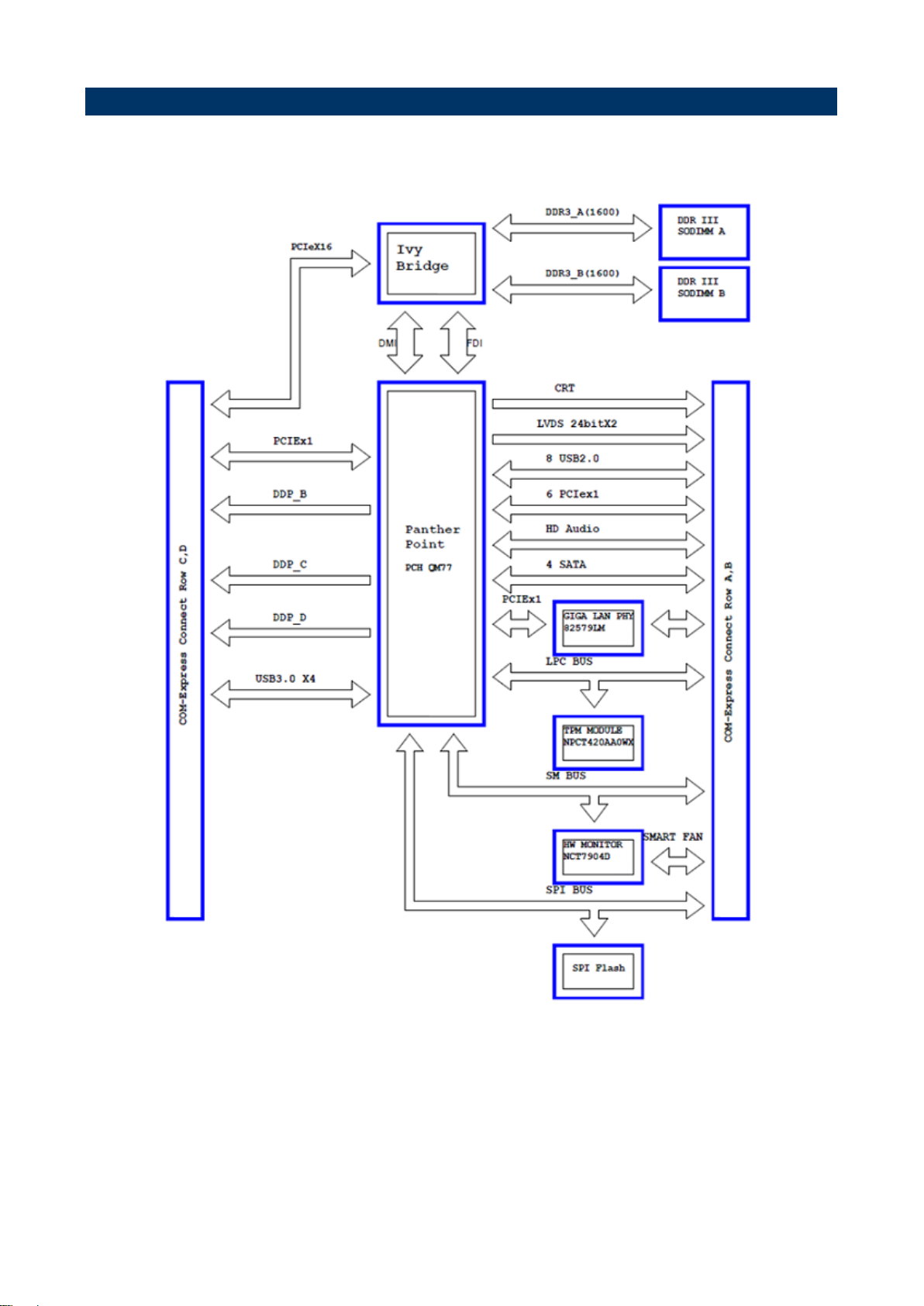
1.6 Architecture Overview—Block Diagram
The following block diagram shows the architecture and main components of ESM-QM77B.
10 ESM-QM77B User’s Manual

User’s Manual
11
2. Hardware
Configuration
ESM-QM77B User’s Manual
ESM-QM77B
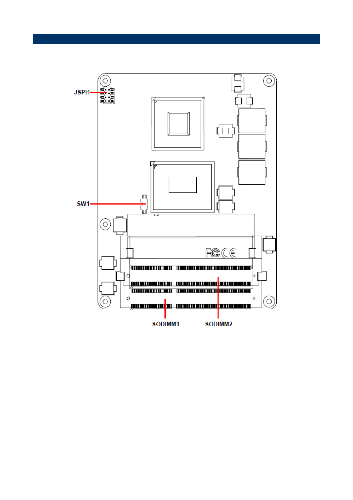
2.1 Product Overview
12 ESM-QM77B User’s Manual
User’s Manual
13
ESM-QM77B User’s Manual

ESM-QM77B
2.2 Installation Procedure
This chapter explains you the instructions of how to setup your system.
1. Turn off the power supply.
2. Insert the DIMM module (be careful with the orientation).
3. Insert all external cables for hard disk, floppy, keyboard, mouse, USB etc. except for flat
panel. A CRT monitor must be connected in order to change CMOS settings to support
flat panel.
4. Connect power supply to the board via the ATXPWR.
5. Turn on the power.
6. Enter the BIOS setup by pressing the delete key during boot up. Use the "Save & Exit \
Restore Defaults" feature.
7. If TFT panel display is to be utilized, make sure the panel voltage is correctly set before
connecting the display cable and turning on the power.
14 ESM-QM77B User’s Manual
User’s Manual
15
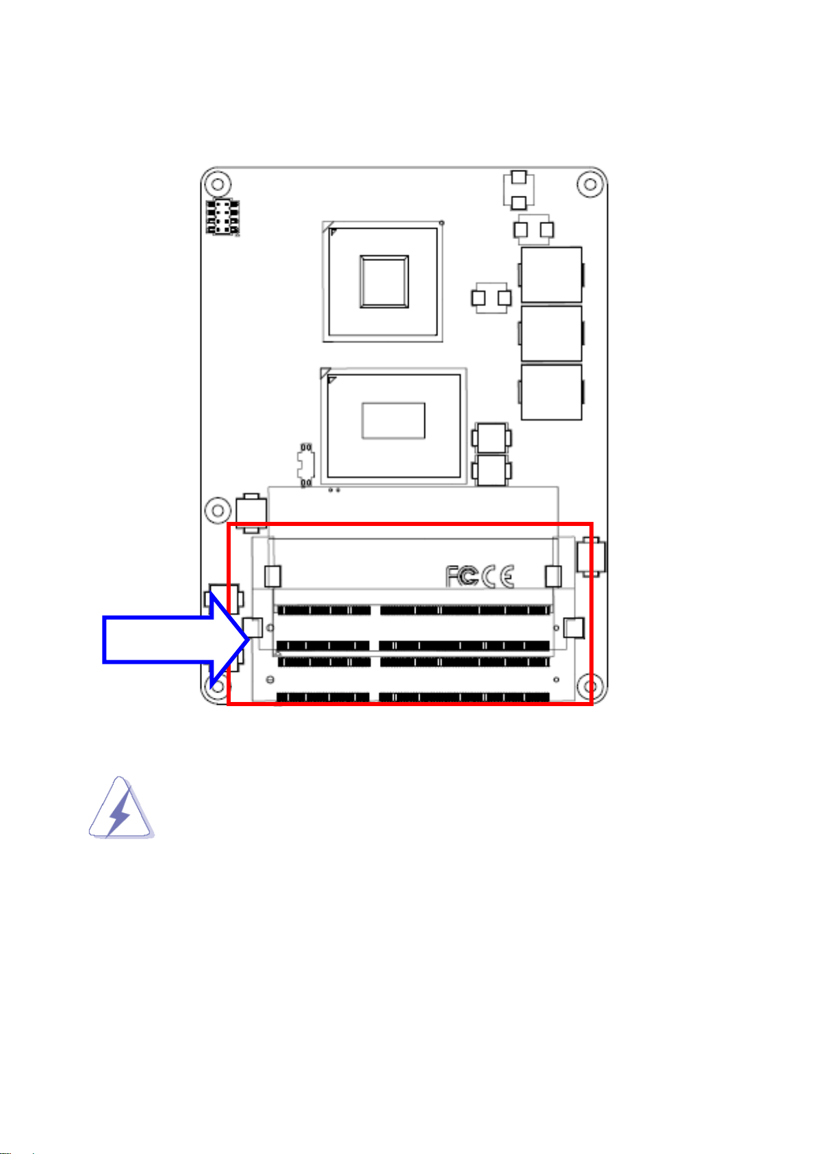
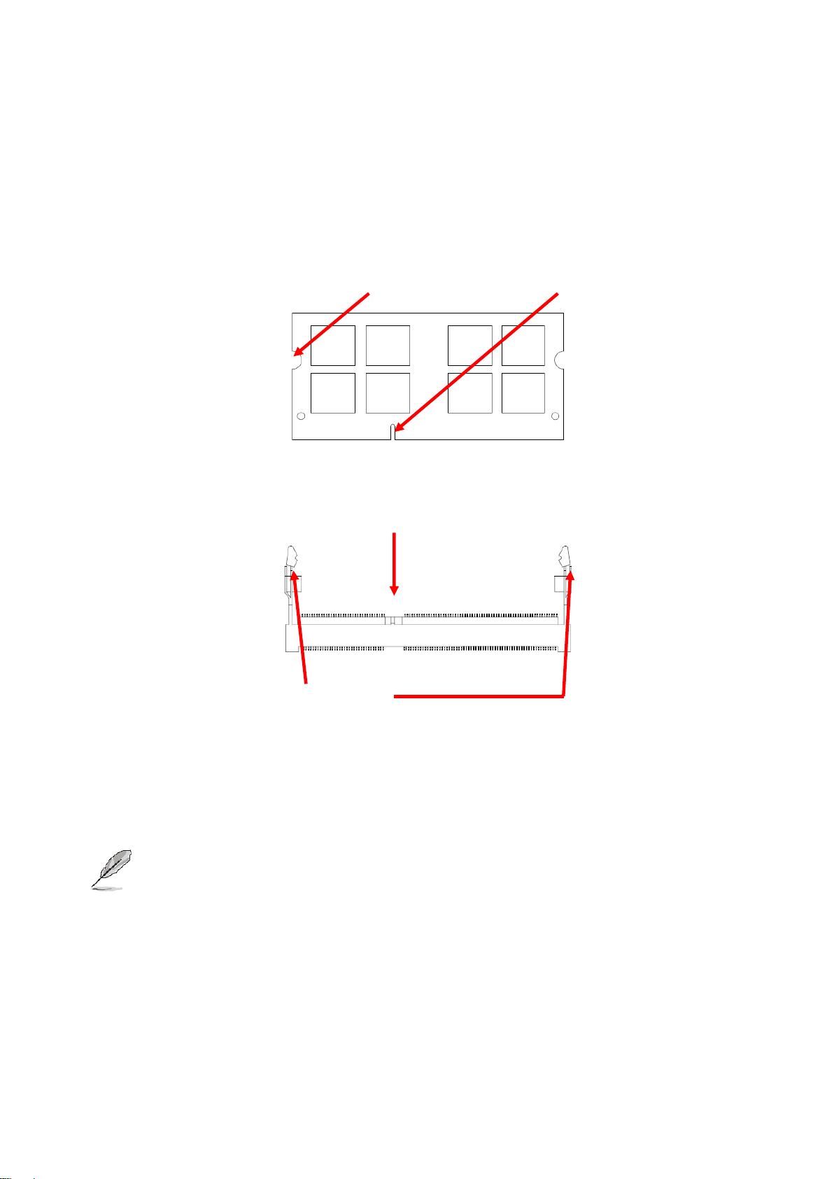
SODIMM
2.2.1 Main Memory
ESM-QM77B provides one 204-pin DDR3 SODIMM socket, supports up to 16GB DDR3
1333/1600 SDRAM
Make sure to unplug the power supply before adding or removing DIMMs or
other system components. Failure to do so may cause severe damage to
board and components.
ESM-QM77B User’s Manual
ESM-QM77B
Mounting Notch
Notch Key
Ejector
204-pin DDR3 SODIMM
Locate the SODIMM socket on the board.
Carefully hold two edges of the SODIMM module. avoid touching its connectors.
Align the notch key on the module with the rib on the slot.
Firmly press the modules into the socket which automatically snaps into the mounting
notch. Do not force the SODIMM module in with extra force as the SODIMM module
only fits in one direction.
To remove SODIMM modules, simultaneously push the two ejector tabs outward,
then pull out the SODIMM module.
Note:
(1) Please do not change any DDR3 SDRAM parameter in BIOS setup to increase
your system’s performance without acquiring technical information in advance.
(2) Static electricity can damage the electronic components of the computer or
optional boards. Before proceeding, ensure that you are discharged of static
electricity by briefly touching a grounded metal object.
16 ESM-QM77B User’s Manual
User’s Manual
17
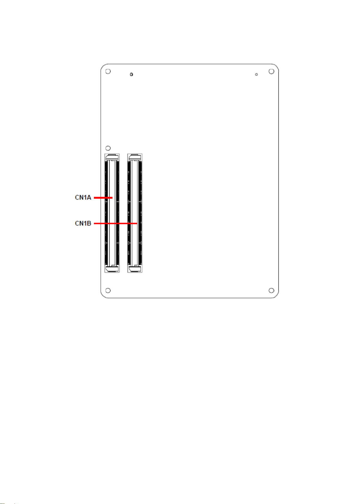
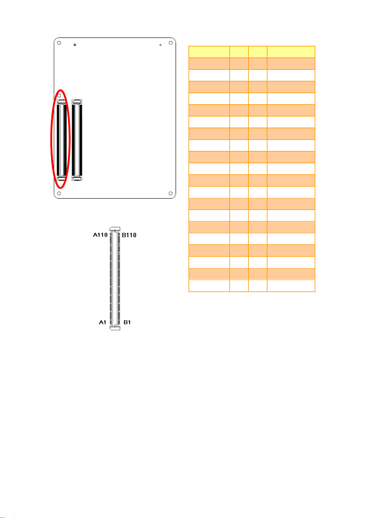
Connectors
Label
Function
Note
JSPI1
(Reserved for BIOS programming)
4 x 2 header, pitch 2.0mm
CN1A
COM Express connector 1
CN1B
COM Express connector 2
SODIMM1
204-pin DDR3 SDRAM DIMM socket
SODIMM2
204-pin DDR3 SDRAM DIMM socket
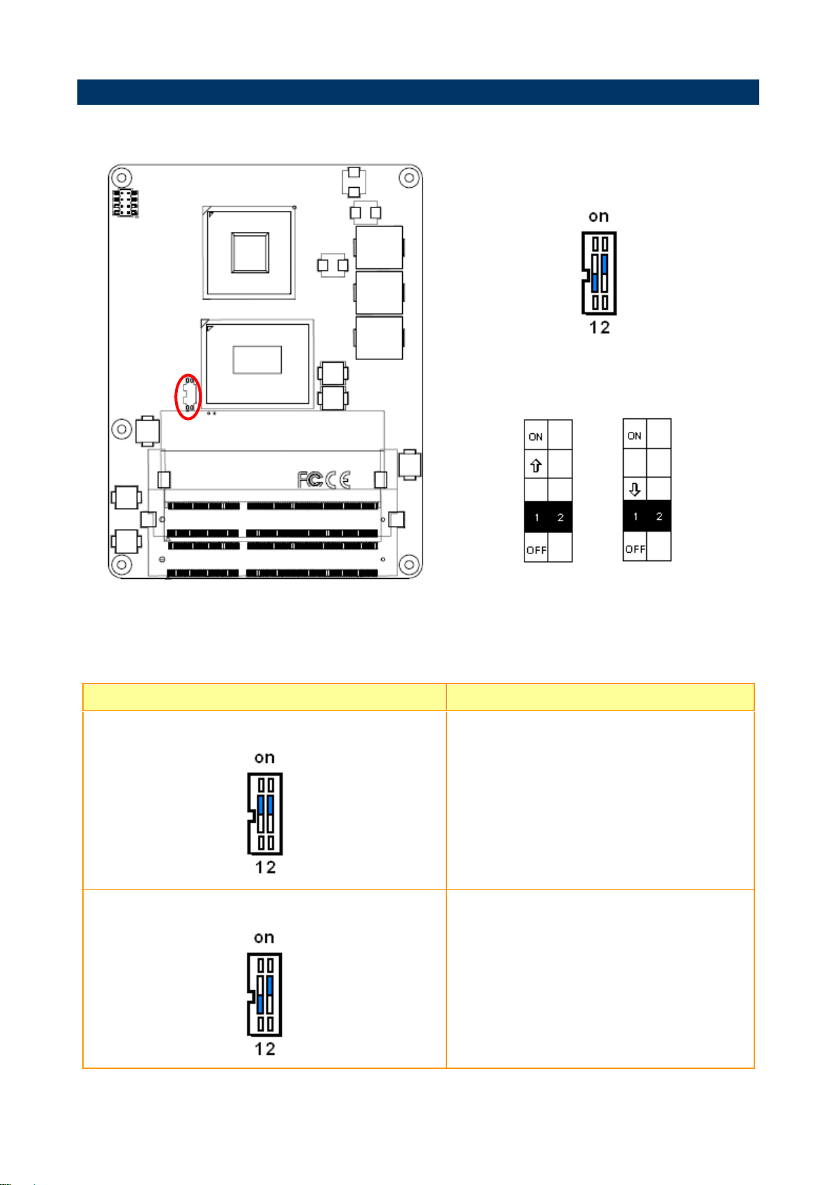
SW1
AT/ATX mode selector
2.3 Connector List
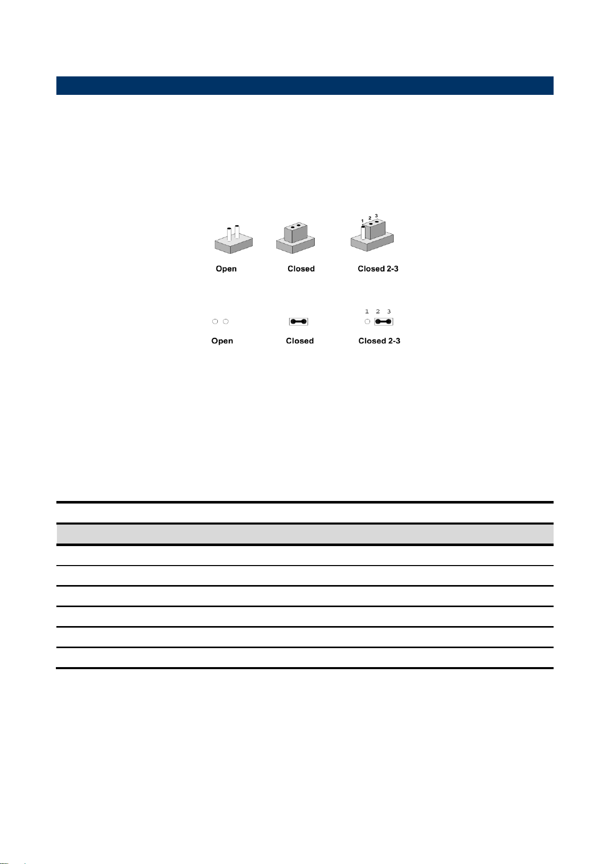
You can configure your board to match the needs of your application by setting jumpers. A
jumper is the simplest kind of electric switch.
It consists of two metal pins and a small metal clip (often protected by a plastic cover) that
slides over the pins to connect them. To “close” a jumper you connect the pins with the clip.
To “open” a jumper you remove the clip. Sometimes a jumper will have three pins, labeled 1,
2, and 3. In this case, you would connect either two pins.
The jumper settings are schematically depicted in this manual as follows:
A pair of needle-nose pliers may be helpful when working with jumpers.
Connectors on the board are linked to external devices such as hard disk drives, a
keyboard, or floppy drives. In addition, the board has a number of jumpers that allow you to
configure your system to suit your application.
If you have any doubts about the best hardware configuration for your application, contact
your local distributor or sales representative before you make any changes.
The following tables list the function of each of the board’s jumpers and connectors.
ESM-QM77B User’s Manual
ESM-QM77B
*Default
AT/ATX mode
AT mode ATX mode*
AT/ATX mode
Description
AT mode
This Mode supports AT power supply, no need
to press Power button to enable power on/off
ATX mode
This Mode supports ATX power supply. Press the
ATX power button to enable power on/off
2.4 Setting Jumpers & Connectors
2.4.1 AT/ATX mode selector (SW1)
2.4.1.1 Signal Description –AT/ATX mode selection
18 ESM-QM77B User’s Manual
19
Signal
PIN
PIN
Signal
GND
A1
B1
GND
GBE0_MDI3-
A2
B2
GBE0_ACT#
GBE0_MDI3+
A3
B3
LPC_FRAME#
GBE0_LINK100#
A4
B4
LPC_AD0
GBE0_LINK1000#
A5
B5
LPC_AD1
GBE0_MDI2-
A6
B6
LPC_AD2
GBE0_MDI2+
A7
B7
LPC_AD3
GBE0_LINK#
A8
B8
LPC_DRQ0#
GBE0_MDI1-
A9
B9
LPC_DRQ1#
GBE0_MDI1+
A10
B10
LPC_CLK
GND
A11
B11
GND
GBE0_MDI0-
A12
B12
PWRBTN#
GBE0_MDI0+
A13
B13
SMB_CK
GBE0_CTREF
A14
B14
SMB_DAT
SUS_S3#
A15
B15
SMB_ALERT#
SATA0_TX+
A16
B16
SATA1_TX+
SATA0_TX-
A17
B17
SATA1_TX-
SUS_S4#
A18
B18
SUS_STAT#
SATA0_RX+
A19
B19
SATA1_RX+
SATA0_RX-
A20
B20
SATA1_RX-
GND
A21
B21
GND
SATA2_TX+
A22
B22
SATA3_TX+
SATA2_TX-
A23
B23
SATA3_TX-
SUS_S5#
A24
B24
PWR_OK
SATA2_RX+
A25
B25
SATA3_RX+
SATA2_RX-
A26
B26
SATA3_RX-
BATLOW#
A27
B27
WDT
(S)ATA_ACT#
A28
B28
AC/HDA_SDIN2
AC/HDA_SYNC
A29
B29
AC/HDA_SDIN1
AC/HDA_RST#
A30
B30
AC/HDA_SDIN0
2.4.2 COM Express Connector 1 (CN1A)
User’s Manual
ESM-QM77B User’s Manual
ESM-QM77B
Signal
PIN
PIN
Signal
GND
A31
B31
GND
AC/HDA_BITCLK
A32
B32
SPKR
AC/HDA_SDOUT
A33
B33
I2C_CK
BIOS_DIS0#
A34
B34
I2C_DAT
THRMTRIP#
A35
B35
THRM#
USB6-
A36
B36
USB7-
USB6+
A37
B37
USB7+
USB_6_7_OC#
A38
B38
USB_4_5_OC#
USB4-
A39
B39
USB5-
USB4+
A40
B40
USB5+
GND
A41
B41
GND
USB2-
A42
B42
USB3-
USB2+
A43
B43
USB3+
USB_2_3_OC#
A44
B44
USB_0_1_OC#
USB0-
A45
B45
USB1-
USB0+
A46
B46
USB1+
VCC_RTC
A47
B47
EXCD1_PERST#
EXCD0_PERST#
A48
B48
EXCD1_CPPE#
EXCD0_CPPE#
A49
B49
SYS_RESET#
LPC_SERIRQ
A50
B50
CB_RESET#
GND
A51
B51
GND
PCIE_TX5+
A52
B52
PCIE_RX5+
PCIE_TX5-
A53
B53
PCIE_RX5-
GPI0
A54
B54
GPO1
PCIE_TX4+
A55
B55
PCIE_RX4+
PCIE_TX4-
A56
B56
PCIE_RX4-
GND
A57
B57
GPO2
PCIE_TX3+
A58
B58
PCIE_RX3+
PCIE_TX3-
A59
B59
PCIE_RX3-
GND
A60
B60
GND
20 ESM-QM77B User’s Manual
User’s Manual
21
Signal
PIN
PIN
Signal
PCIE_TX2+
A61
B61
PCIE_RX2+
PCIE_TX2-
A62
B62
PCIE_RX2-
GPI1
A63
B63
GPO3
PCIE_TX1+
A64
B64
PCIE_RX1+
PCIE_TX1-
A65
B65
PCIE_RX1-
GND
A66
B66
WAKE0#
GPI2
A67
B67
WAKE1#
PCIE_TX0+
A68
B68
PCIE_RX0+
PCIE_TX0-
A69
B69
PCIE_RX0-
GND
A70
B70
GND
LVDS_A0+
A71
B71
LVDS_B0+
LVDS_A0-
A72
B72
LVDS_B0-
LVDS_A1+
A73
B73
LVDS_B1+
LVDS_A1-
A74
B74
LVDS_B1-
LVDS_A2+
A75
B75
LVDS_B2+
LVDS_A2-
A76
B76
LVDS_B2-
LVDS_VDD_EN
A77
B77
LVDS_B3+
LVDS_A3+
A78
B78
LVDS_B3-
LVDS_A3-
A79
B79
LVDS_BKLT_EN
GND
A80
B80
GND
LVDS_A_CK+
A81
B81
LVDS_B_CK+
LVDS_A_CK-
A82
B82
LVDS_B_CK-
LVDS_I2C_CK
A83
B83
LVDS_BKLT_CTRL
LVDS_I2C_DAT
A84
B84
VCC_5V_SBY
GPI3
A85
B85
VCC_5V_SBY
RSVD1
A86
B86
VCC_5V_SBY
RSVD2
A87
B87
VCC_5V_SBY
PCIE_CLK_REF+
A88
B88
BIOS_DIS1#
PCIE_CLK_REF--
A89
B89
VGA_RED
GND
A90
B90
GND
ESM-QM77B User’s Manual
ESM-QM77B
Signal
PIN
PIN
Signal
SPI_POWER
A91
B91
VGA_GRN
SPI_MISO
A92
B92
VGA_BLU
GPO0
A93
B93
VGA_HSYNC
SPI_CLK
A94
B94
VGA_VSYNC
SPI_MOSI
A95
B95
VGA_I2C_CK
PP_TPM
A96
B96
VGA_I2C_DAT
TYPE10#
A97
B97
SPI_CS#
NC
A98
B98
NC
NC
A99
B99
NC
GND
A100
B100
GND
NC
A101
B101
FAN_PWMOUT
NC
A102
B102
FAN_TACHIN
LID#
A103
B103
SLEEP#
VIN
A104
B104
VIN
VIN
A105
B105
VIN
VIN
A106
B106
VIN
VIN
A107
B107
VIN
VIN
A108
B108
VIN
VIN
A109
B109
VIN
GND
A110
B110
GND
22 ESM-QM77B User’s Manual

23
Signal
Signal Description
AC/HDA_SYNC
HD Audio Sync
AC/HDA _RST#
HD Audio Reset
AC/HDA _SDIN[0:2]
Audio CODEC Serial Data
AC/HDA _BITCLK
HD Audio Clock
AC/HDA _SDOUT
HD Audio Data
Signal
Signal Description
GBE0_MD[0:3] +/-
Gigabit Ethernet Controller 0: Media Dependent Interface Differential Pairs 0,1,2,3.
The MDI can operate in 1000, 100 and 10 Mbit / sec modes. Some pairs are
unused in some modes, per the following:
1000B-T
100B-T
10B-T
MDI[0]+/-
B1_DA+/
TX+/-
TX+/-
MDI[1]+/
B1_DB+/
RX+/-
RX+/-
MDI[2]+/
B1_DC+/
X
X
MDI[3]+/
B1_DD+/
X
X
GBE0_ACT#
Gigabit Ethernet Controller 0 activity indicator, active low.
GBE0_Link#
Gigabit Ethernet Controller 0 link indicator, active low.
GBE0_Link100#
Gigabit Ethernet Controller 0 100 Mbit / sec link indicator, active low.
GBE0_Lin1000#
Gigabit Ethernet Controller 0 1000 Mbit / sec link indicator, active low.
Signal
Signal Description
GPI[0:4]
General purpose input pins.
GPO[0:4]
General purpose output pins.
Signal
Signal Description
LVDS_BKLT_CTRL
LVDS panel backlight brightness control.
LVDS_VDD_EN
LVDS panel power enable.
2.4.2.1 Signal Description – COM Express Connector 1 (CN1A)
2.4.2.1.1 Audio Signals
2.4.2.1.2 Gigabit Ethernet Signals
User’s Manual
2.4.2.1.3 GPIO Signals
2.4.2.1.4 Flat Panel LVDS Signals
ESM-QM77B User’s Manual
 Loading...