

Page 1

ESM-CDV
COM Express Type 2 CPU Module
User’s Manual
1st Ed – 18 December 2012
Part No. E2047286400R
Page 2

ESM-CDV User’s Manual
FCC Statement
Copyright Notice
Disclaimer
THIS DEVICE COMPLIES WITH PART 15 FCC RULES. OPERATION IS
SUBJECT TO THE FOLLOWING TWO CONDITIONS:
(1) THIS DEVICE MAY NOT CAUSE HARMFUL INTERFERENCE.
(2) THIS DEVICE MUST ACCEPT ANY INTERFERENCE RECEIVED INCLUDING
INTERFERENCE THAT MAY CAUSE UNDESIRED OPERATION.
THIS EQUIPMENT HAS BEEN TESTED AND FOUND TO COMPLY WITH THE LIMITS
FOR A CLASS "A" DIGITAL DEVICE, PURSUANT TO PART 15 OF THE FCC RULES.
THESE LIMITS ARE DESIGNED TO PROVIDE REASONABLE PROTECTION AGAINST
HARMFUL INTERFERENCE WHEN THE EQUIPMENT IS OPERATED IN A
COMMERCIAL ENVIRONMENT. THIS EQUIPMENT GENERATES, USES, AND CAN
RADIATE RADIO FREQUENCY ENERGY AND, IF NOT INSTALLED AND USED IN
ACCORDANCE WITH THE INSTRUCTION MANUAL, MAY CAUSE HARMFUL
INTERFERENCE TO RADIO COMMUNICATIONS.
OPERATION OF THIS EQUIPMENT IN A RESIDENTIAL AREA IS LIKELY TO CAUSE
HARMFUL INTERFERENCE IN WHICH CASE THE USER WILL BE REQUIRED TO
CORRECT THE INTERFERENCE AT HIS OWN EXPENSE.
Copyright 2013 Avalue Technology Inc., ALL RIGHTS RESERVED.
No part of this document may be reproduced, copied, translated, or transmitted in any form
or by any means, electronic or mechanical, for any purpose, without the prior written
permission of the original manufacturer.
Avalue Technology Inc. reserves the right to make changes, without notice, to any product,
including circuits and/or software described or contained in this manual in order to improve
design and/or performance. Avalue Technology assumes no responsibility or liability for the
use of the described product(s), conveys no license or title under any patent, copyright, or
masks work rights to these products, and makes no representations or warranties that
these products are free from patent, copyright, or mask work right infringement, unless
otherwise specified. Applications that are described in this manual are for illustration
purposes only. Avalue Technology Inc. makes no representation or warranty that such
application will be suitable for the specified use without further testing or modification.
2 ESM-CDV User’s Manual
Page 3

ESM-CDV User’s Manual
A Message to the Customer
Avalue Customer Services
Each and every Avalue’s product is built to the most exacting specifications to ensure
reliable performance in the harsh and demanding conditions typical of industrial
environments. Whether your new Avalue device is destined for the laboratory or the factory
floor, you can be assured that your product will provide the reliability and ease of operation
for which the name Avalue has come to be known.
Your satisfaction is our primary concern. Here is a guide to Avalue’s customer services. To
ensure you get the full benefit of our services, please follow the instructions below carefully.
Technical Support
We want you to get the maximum performance from your products. So if you run into
technical difficulties, we are here to help. For the most frequently asked questions, you can
easily find answers in your product documentation. These answers are normally a lot more
detailed than the ones we can give over the phone. So please consult the user’s manual
first.
To receive the latest version of the user’s manual; please visit our Web site at:
http://www.avalue.com.tw/
Product Warranty
Avalue warrants to you, the original purchaser, that each of its products will be free from
defects in materials and workmanship for two years from the date of purchase.
This warranty does not apply to any products that have been repaired or altered by people
other than repair personnel authorized by Avalue, or that have been subject of misuse,
abuse, accident or improper installation. Avalue assumes no liability under the terms of this
warranty as a consequence of such events. Because of Avalue’s high quality-control
standards and rigorous testing, most of our customers never need to use our repair service.
If any of Avalue’s products is defective, it will be repaired or replaced at no charge during
the warranty period. For out-of-warranty repairs, you will be billed according to the cost of
replacement materials, service time, and freight. Please consult your dealer for more
details. If you think you have a defective product, follow these steps:
1. Collect all the information about the problem encountered. (For example, CPU type and
speed, Avalue’s products model name, hardware & BIOS revision number, other
hardware and software used, etc.) Note anything abnormal and list any on-screen
messages you get when the problem occurs.
2. Call your dealer and describe the problem. Please have your manual, product, and any
helpful information available.
ESM-CDV User’s Manual 3
Page 4

ESM-CDV User’s Manual
Headquarters and Branch
Avalue USA
Avalue Technology Inc.
7F, 228, Lian-cheng Road, Chung Ho City, Taipei,
Taiwan
Tel:+886-2-8226-2345
Fax: +886-2-8226-2777
Information:sales@avalue.com.tw
Service: service@avalue.com.tw
Avalue Technology Inc.
9 Timber Lane, Marlboro, NJ 07746-1443
Tel: (732) 414-6500
Fax: (732) 414-6501
Information: sales@avalue-usa.com
Service: support@avalue-usa.com
BCM Advanced Research
Avalue Europe
BCM Advanced Research
an Avalue Company
7 Marconi, Irvine, CA92618
Tel: +1-949-470-1888
Fax: +1-949-470-0971
Information: BCMSales@bcmcom.com
Web: www.bcmcom.com
Avalue Europe A/S
Moelledalen 22C, 3140
Aalsgaarde, Denmark
Tel: +45-7025-0310
Fax:+45-4975-5026
Information: sales.europe@avalue.com.tw
Service: service.europe@avalue.com.tw
Avalue China
Avalue Japan
Avalue Technology Inc.
Room 805, Building 9,No.99 Tianzhou Rd.,
Caohejing Development Area,
Xuhui District, Shanghai
Tel: +86-21-5169-3609
Fax:+86-21-5445-3266
Information: sales.china@avalue.com.cn
Service: service@avalue.com.tw
Avalue Technology Inc.
3F Ishiyama-Bldg, 1-6-1 Taito,
Taito-ku, Tokyo 110-0016 Japan
Tel: +81-3-5807-2321
Fax: +81-3-5807-2322
Information: sales.japan@avalue.com.tw
Service: service@avalue.com.tw
3. If your product is diagnosed as defective, obtain an RMA (return material authorization)
number from your dealer. This allows us to process your good return more quickly.
4. Carefully pack the defective product, a complete Repair and Replacement Order Card
and a photocopy proof of purchase date (such as your sales receipt) in a shippable
container. A product returned without proof of the purchase date is not eligible for
warranty service.
5. Write the RMA number visibly on the outside of the package and ship it prepaid to your
dealer.
4 ESM-CDV User’s Manual
Page 5

ESM-CDV User’s Manual
Content
1. Getting Started ............................................................................................................ 7
1.1 Safety Precautions .......................................................................................... 7
1.2 Packing List .................................................................................................... 7
1.3 Document Amendment History ....................................................................... 8
1.4 Manual Objectives .......................................................................................... 9
1.5 System Specifications .................................................................................. 10
1.6 Architecture Overview—Block Diagram........................................................ 12
2. Hardware Configuration ........................................................................................... 13
2.1 Product Overview ......................................................................................... 14
2.2 Installation Procedure ................................................................................... 16
2.2.1 Main Memory ........................................................................................... 17
2.3 Jumper and Connector List .......................................................................... 19
2.4 Setting Jumpers & Connectors ..................................................................... 20
2.4.1 AT/ATX mode selector (SW1) .................................................................. 20
2.4.1.1 Signal Description –AT/ATX mode selection ................................. 20
2.4.2 COM Express Connector 1 (CN1A) ......................................................... 21
2.4.2.1 Signal Description – COM Express Connector 1 (CN1A) .............. 25
2.4.3 COM Express Connector 2 (CN1B) ......................................................... 29
2.4.3.1 Signal Description – COM Express Connector 2 (CN1B) .............. 33
3.BIOS Setup .................................................................................................................... 35
3.1 Introduction ................................................................................................... 36
3.2 Starting Setup ............................................................................................... 36
3.3 Using Setup .................................................................................................. 37
3.4 Getting Help ................................................................................................. 38
3.5 In Case of Problems ..................................................................................... 38
3.6 BIOS setup ................................................................................................... 39
3.6.1 Main Menu ............................................................................................... 39
3.6.1.1 System Language .......................................................................... 40
3.6.1.2 System Date .................................................................................. 40
3.6.1.3 System Time .................................................................................. 40
3.6.2 Advanced BIOS settings .......................................................................... 41
3.6.2.1 PCI Subsystem Settings ................................................................ 41
3.6.2.2 ACPI Settings ................................................................................ 42
3.6.2.3 S5 RTC Wake Settings .................................................................. 43
3.6.2.4 CPU Configuration ......................................................................... 43
3.6.2.5 Thermal Configuration ................................................................... 44
ESM-CDV User’s Manual 5
Page 6

ESM-CDV User’s Manual
3.6.2.6 IDE Configuration ........................................................................... 47
3.6.2.7 Intel Fast Flash Standby ................................................................ 48
3.6.2.8 USB Configuration ......................................................................... 48
3.6.2.9 H/W Monitor ................................................................................... 49
3.6.2.10 Smart Settings ............................................................................. 50
3.6.2.11 Super IO Configuration ................................................................ 50
3.6.2.12 PPM configuration ........................................................................ 55
3.6.3 Advanced Chipset Features ..................................................................... 55
3.6.3.1 Host bridge .................................................................................... 56
3.6.3.2 South bridge .................................................................................. 59
3.6.4 Boot settings ............................................................................................ 64
3.6.5 Security .................................................................................................... 65
3.6.5.1 Administrator Password ................................................................. 65
3.6.5.2 User Password............................................................................... 65
3.6.6 Save & Exit .............................................................................................. 66
3.6.6.1 Save Changes and Exit ................................................................. 66
3.6.6.2 Discard Changes and Exit ............................................................. 66
3.6.6.3 Save Changes and Reset .............................................................. 67
3.6.6.4 Discard Changes and Reset .......................................................... 67
3.6.6.5 Save Changes ............................................................................... 67
3.6.6.6 Discard Changes ........................................................................... 67
3.6.6.7 Restore Defaults ............................................................................ 67
3.6.6.8 Save as User Defaults ................................................................... 67
3.6.6.9 Restore User Defaults .................................................................... 67
3.6.6.10 Boot override................................................................................ 67
4. Drivers Installation....................................................................................................... 68
4.1 Install VGA Driver ......................................................................................... 69
4.2 Install Ethernet Driver (For Intel 82574L) ..................................................... 70
4.3 Install Chipset Driver .................................................................................... 72
5. Mechanical Drawing .................................................................................................... 74
6 ESM-CDV User’s Manual
Page 7
ESM-CDV User’s Manual
1. Getting Started
1.1 Safety Precautions
Warning!
Always completely disconnect the power cord from your
chassis whenever you work with the hardware. Do not
make connections while the power is on. Sensitive
electronic components can be damaged by sudden power
surges. Only experienced electronics personnel should
open the PC chassis.
Caution!
Always ground yourself to remove any static charge before
touching the CPU card. Modern electronic devices are very
sensitive to static electric charges. As a safety precaution,
use a grounding wrist strap at all times. Place all electronic
components in a static-dissipative surface or static-shielded
bag when they are not in the chassis.
Always note that improper disassembling action could cause damage to the
motherboard. We suggest not removing the heatsink without correct
instructions in any circumstance. If you really have to do this, please contact
us for further support.
1.2 Packing List
Before you begin installing your single board, please make sure that the
following materials have been shipped:
1 x ESM-CDV COM Express Module
1 x Quick Installation Guide
1 x DVD-ROM contains the followings:
— User’s Manual (this manual in PDF file)
— Chipset and Ethernet driver
ESM-CDV User’s Manual 7
Page 8

ESM-CDV User’s Manual
Revision
Date
By
Comment
1st
December
2012
Avalue
Initial Release
1.3 Document Amendment History
8 ESM-CDV User’s Manual
Page 9

ESM-CDV User’s Manual
1.4 Manual Objectives
This manual describes in details Avalue Technology ESM-CDV Single Board.
We have tried to include as much information as possible but we have not duplicated
information that is provided in the standard IBM Technical References, unless it proved to
be necessary to aid in the understanding of this board.
We strongly recommend that you study this manual carefully before attempting to set up
ESM-CDV series or change the standard configurations. Whilst all the necessary
information is available in this manual we would recommend that unless you are confident,
you contact your supplier for guidance.
Please be aware that it is possible to create configurations within the CMOS RAM that
make booting impossible. If this should happen, clear the CMOS settings, (see the
description of the Jumper Settings for details).
If you have any suggestions or find any errors regarding this manual and want to inform us
of these, please contact our Customer Service department with the relevant details.
ESM-CDV User’s Manual 9
Page 10

ESM-CDV User’s Manual
System
CPU
Intel Atom Processor D2550 (N2800 and N2600 for optional)
BIOS
AMI uEFI BIOS, 16Mbit SPI Flash ROM
System Chipset
Intel NM10
System Memory
One DDR3 SO-DIMM socket, data transfer rate supports 800MT/s and 1066MT/s,
up to 4GB
H/W monitor
Nuvoton NCT7904D H/W monitor IC onboard
Watchdog Timer
Nuvoton NCT7904D integrated
- H/W Reset asserted
- 1us – 10min.
Display
Chipset
D2550/N2800/N2600 integrated graphics
One CH-7511B onboard
Interface
2-ch 24-bit LVDS, resolution up to 1920x1080
VGA supported, resolution up to 1920x1200
Ethernet
Chipset
Intel 82574L GbE controller
Interface
10/100/1000base-Tx
Audio
Chipset
Intel NM10 integrated
Interface
HD audio codec interface
Storage
Interface
2 x SATA port
1 x PATA port
Digital
Input/output
Chipset
TI PCA9555PWR
Interface
4 bits for input and 4 bits for output
I/O
COM Express
Type-2 Connector
2 x PCI master
4 x PCIex1
1 x LPC interface
2 x SATA ports
1 x PATA port
1.5 System Specifications
10 ESM-CDV User’s Manual
Page 11

ESM-CDV User’s Manual
1 x GbE port
8 x USB2.0 ports
1 x HD audio codec interface
1 x 2-ch 24-bit LVDS port
1 x VGA port
1 x SMBus
8-bit GPIO
- 4-bits for input
- 4-bits for output
Mechanical &
Environmental
Power
Requirement
5VSB & VIN or VIN only.
- 5VSB +-5%
- VIN range from +9V(min) ~ +19V(max)
Power Type
AT / ATX
ACPI
Single power ATX Support S0, S3, S4, S5
ACPI 3.0 Compliant
Operating Temp.
0°C ~60°C
Storage Temp.
-40°C ~75°C
Operating
Humidity
0%~90% relative humidity, non-condensing
Size (L x W)
5" x 3.7" (125mm x 95mm)
Weight
0.44 lbs (0.2 Kg)
ESM-CDV User’s Manual 11
Page 12

ESM-CDV User’s Manual
1.6 Architecture Overview—Block Diagram
The following block diagram shows the architecture and main components of ESM-CDV.
12 ESM-CDV User’s Manual
Page 13

ESM-CDV User’s Manual
2. Hardware
Configuration
ESM-CDV User’s Manual 13
Page 14
ESM-CDV User’s Manual
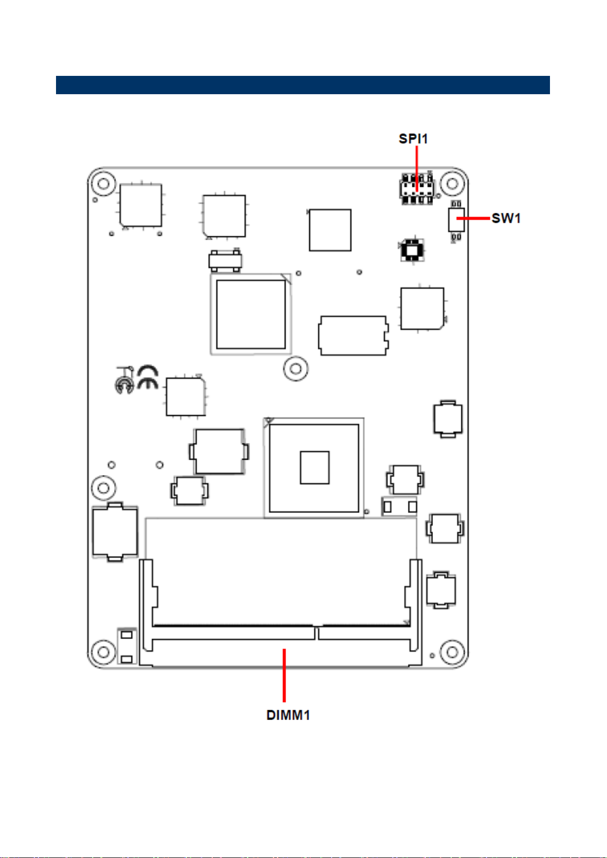
2.1 Product Overview
14 ESM-CDV User’s Manual
Page 15
ESM-CDV User’s Manual
ESM-CDV User’s Manual 15
Page 16

ESM-CDV User’s Manual
2.2 Installation Procedure
This chapter explains you the instructions of how to setup your system.
1. Turn off the power supply.
2. Insert the DIMM module (be careful with the orientation).
3. Insert all external cables for hard disk, floppy, keyboard, mouse, USB etc. except for flat
panel. A CRT monitor must be connected in order to change CMOS settings to support
flat panel.
4. Connect power supply to the board via the ATXPWR.
5. Turn on the power.
6. Enter the BIOS setup by pressing the delete key during boot up. Use the "Save & Exit \
Restore Defaults" feature.
7. If TFT panel display is to be utilized, make sure the panel voltage is correctly set before
connecting the display cable and turning on the power.
16 ESM-CDV User’s Manual
Page 17
ESM-CDV User’s Manual
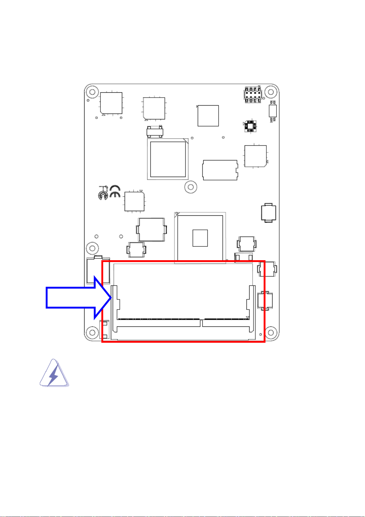
SODIMM
2.2.1 Main Memory
ESM-CDV provides one 204-pin DDR3 SODIMM socket, supports up to 4GB DDR3
800/1066 SDRAM
Make sure to unplug the power supply before adding or removing DIMMs or
other system components. Failure to do so may cause severe damage to
board and components.
ESM-CDV User’s Manual 17
Page 18
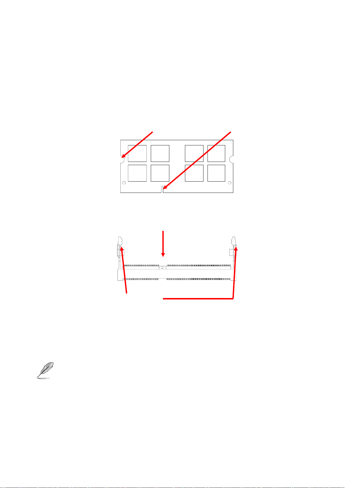
ESM-CDV User’s Manual
Mounting Notch
Notch Key
Ejector
204-pin DDR3 SODIMM
Locate the SODIMM socket on the board.
Carefully hold two edges of the SODIMM module. avoid touching its connectors.
Align the notch key on the module with the rib on the slot.
Firmly press the modules into the socket which automatically snaps into the mounting
notch. Do not force the SODIMM module in with extra force as the SODIMM module
only fits in one direction.
To remove SODIMM modules, simultaneously push the two ejector tabs outward,
then pull out the SODIMM module.
Note:
(1) Please do not change any DDR3 SDRAM parameter in BIOS setup to increase
your system’s performance without acquiring technical information in advance.
(2) Static electricity can damage the electronic components of the computer or
optional boards. Before proceeding, ensure that you are discharged of static
electricity by briefly touching a grounded metal object.
18 ESM-CDV User’s Manual
Page 19

ESM-CDV User’s Manual
Connectors
Label
Function
Note
SPI1
(Reserved for BIOS programming)
4 x 2 header, pitch 2.0mm
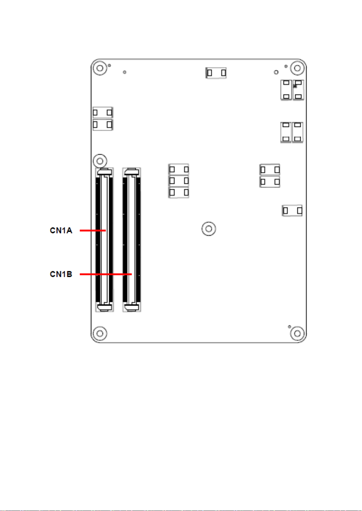
CN1A
COM Express connector 1
CN1B
COM Express connector 2
DIMM1
204-pin DDR3 SDRAM DIMM socket
SW1
AT/ATX mode selector
2.3 Jumper and Connector List
You can configure your board to match the needs of your application by setting jumpers. A
jumper is the simplest kind of electric switch.
It consists of two metal pins and a small metal clip (often protected by a plastic cover) that
slides over the pins to connect them. To “close” a jumper you connect the pins with the clip.
To “open” a jumper you remove the clip. Sometimes a jumper will have three pins, labeled 1,
2, and 3. In this case, you would connect either two pins.
The jumper settings are schematically depicted in this manual as follows:
A pair of needle-nose pliers may be helpful when working with jumpers.
Connectors on the board are linked to external devices such as hard disk drives, a
keyboard, or floppy drives. In addition, the board has a number of jumpers that allow you to
configure your system to suit your application.
If you have any doubts about the best hardware configuration for your application, contact
your local distributor or sales representative before you make any changes.
The following tables list the function of each of the board’s jumpers and connectors.
ESM-CDV User’s Manual 19
Page 20
ESM-CDV User’s Manual
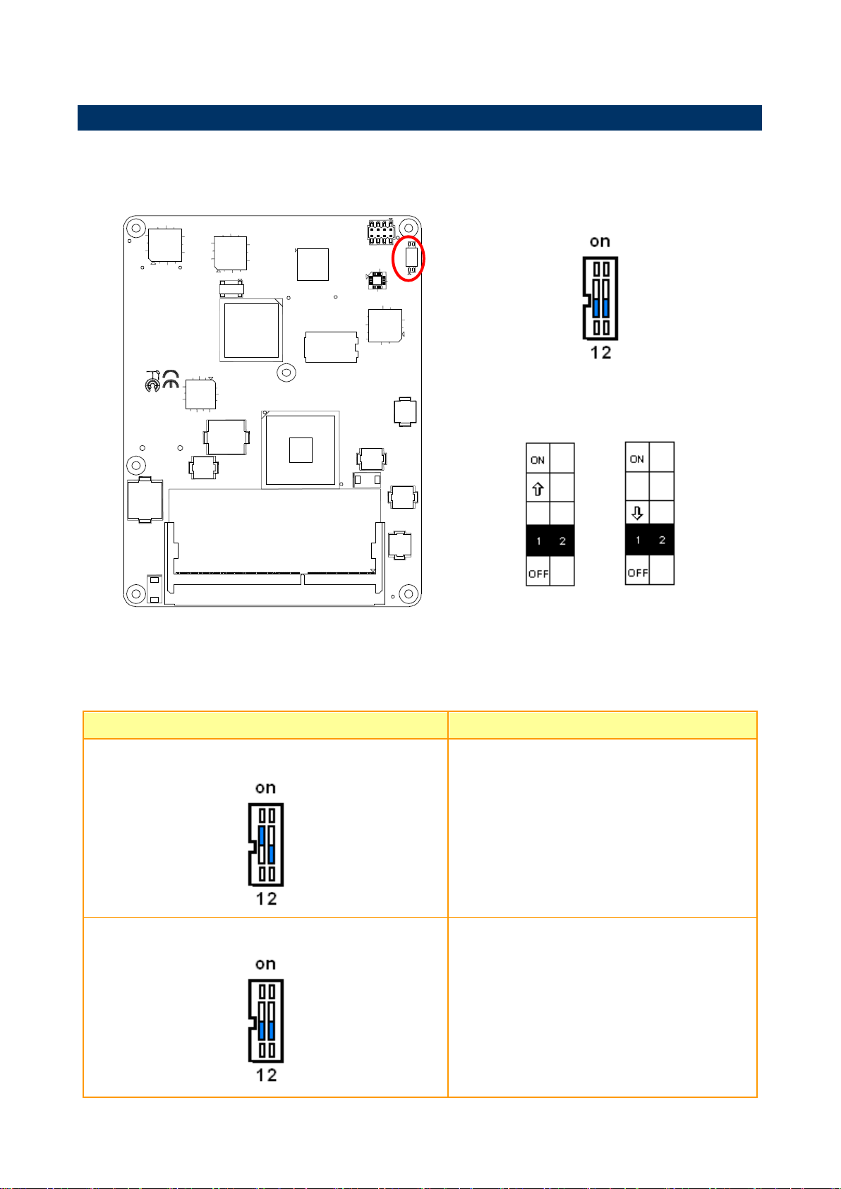
*Default
AT/ATX mode
AT mode ATX mode*
AT/ATX mode
Description
AT mode
This Mode supports AT power supply, no need
to press Power button to enable power on/off
ATX mode
This Mode supports ATX power supply. Press the
ATX power button to enable power on/off
2.4 Setting Jumpers & Connectors
2.4.1 AT/ATX mode selector (SW1)
2.4.1.1 Signal Description –AT/ATX mode selection
20 ESM-CDV User’s Manual
Page 21
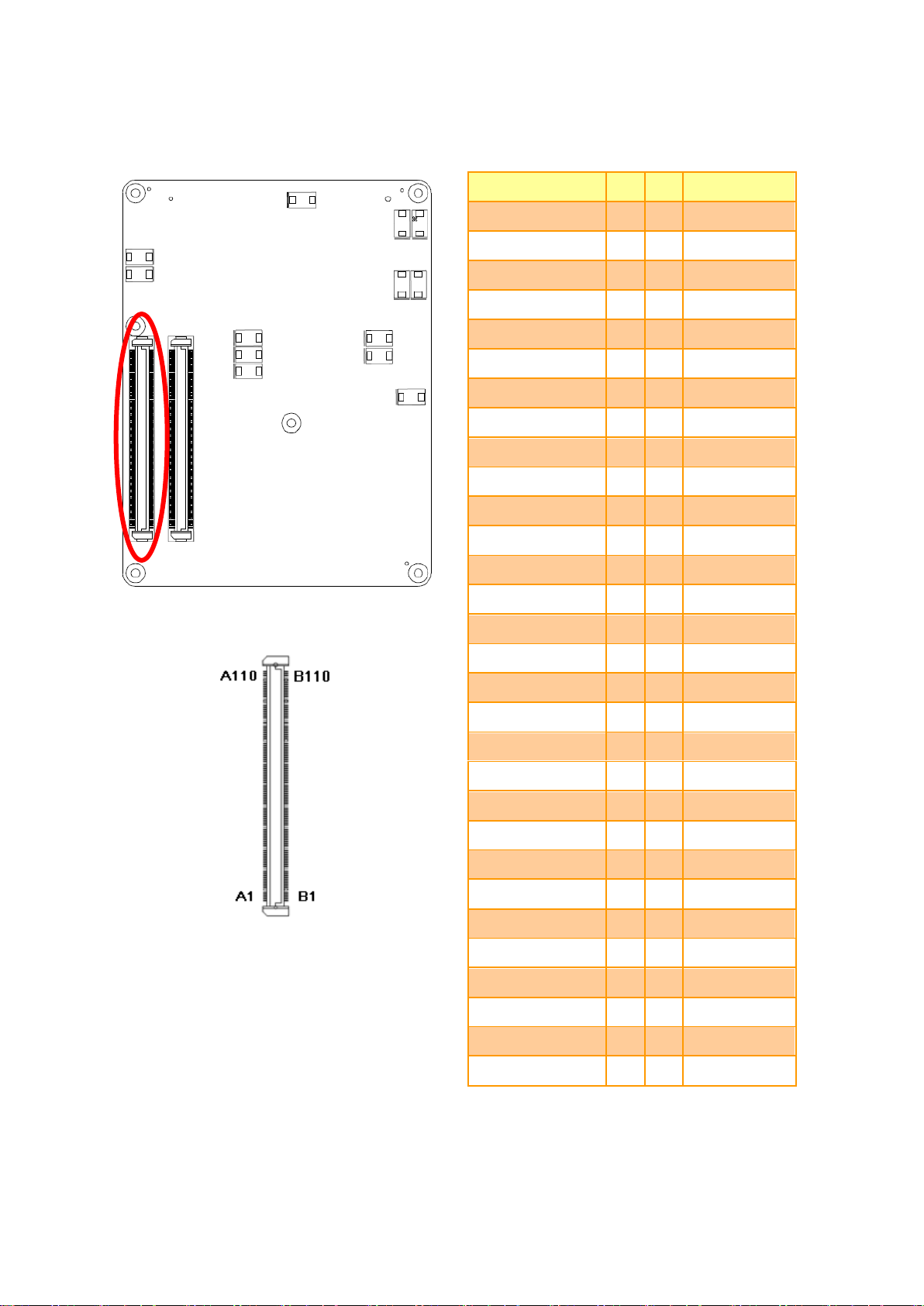
ESM-CDV User’s Manual
Signal
PIN
PIN
Signal
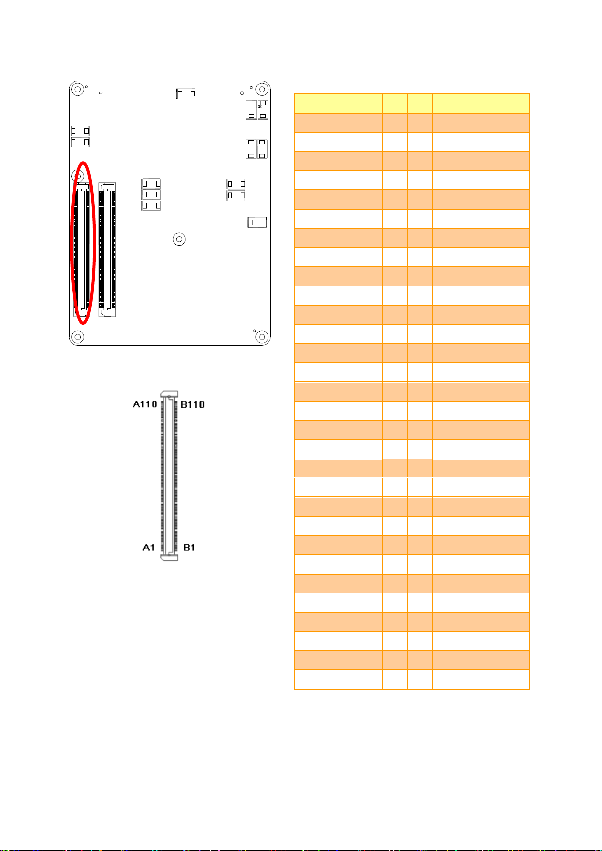
GND
A1
B1
GND
GBE0_MDI3-
A2
B2
GBE0_ACT#
GBE0_MDI3+
A3
B3
LPC_FRAME#
GBE0_LINK100#
A4
B4
LPC_AD0
GBE0_LINK1000#
A5
B5
LPC_AD1
GBE0_MDI2-
A6
B6
LPC_AD2
GBE0_MDI2+
A7
B7
LPC_AD3
GBE0_LINK#
A8
B8
LPC_DRQ0#
GBE0_MDI1-
A9
B9
LPC_DRQ1#
GBE0_MDI1+
A10
B10
LPC_CLK
GND
A11
B11
GND
GBE0_MDI0-
A12
B12
PWRBTN#
GBE0_MDI0+
A13
B13
SMB_CK
GBE0_CTREF
A14
B14
SMB_DAT
SUS_S3#
A15
B15
SMB_ALERT#
SATA0_TX+
A16
B16
SATA1_TX+
SATA0_TX-
A17
B17
SATA1_TX-
SUS_S4#
A18
B18
SUS_STAT#
SATA0_RX+
A19
B19
SATA1_RX+
SATA0_RX-
A20
B20
SATA1_RX-
GND
A21
B21
GND
NC
A22
B22
NC
NC
A23
B23
NC
SUS_S5#
A24
B24
PWR_OK
NC
A25
B25
NC
NC
A26
B26
NC
BATLOW#
A27
B27
WDT
ATA_ACT#
A28
B28
AC_SDIN2
AC_SYNC
A29
B29
AC_SDIN1
AC_RST#
A30
B30
AC_SDIN0
2.4.2 COM Express Connector 1 (CN1A)
ESM-CDV User’s Manual 21
Page 22
ESM-CDV User’s Manual
Signal
PIN
PIN
Signal
GND
A31
B31
GND
AC_BITCLK
A32
B32
SPKR
AC_SDOUT
A33
B33
I2C_CK
BIOS_DISABLE#
A34
B34
I2C_DAT
THRMTRIP#
A35
B35
THRM#
USB6-
A36
B36
USB7-
USB6+
A37
B37
USB7+
USB_6_7_OC#
A38
B38
USB_4_5_OC#
USB4-
A39
B39
USB5-
USB4+
A40
B40
USB5+
GND
A41
B41
GND
USB2-
A42
B42
USB3-
USB2+
A43
B43
USB3+
USB_2_3_OC#
A44
B44
USB_0_1_OC#
USB0-
A45
B45
USB1-
USB0+
A46
B46
USB1+
VCC_RTC
A47
B47
EXCD1_PERST#
EXCD0_PERST#
A48
B48
EXCD1_CPPE#
EXCD0_CPPE#
A49
B49
SYS_RESET#
LPC_SERIRQ
A50
B50
CB_RESET#
GND
A51
B51
GND
NC
A52
B52
NC
NC
A53
B53
NC
GPI0
A54
B54
GPO1
NC
A55
B55
NC
NC
A56
B56
NC
GND
A57
B57
GPO2
PCIE_TX3+
A58
B58
PCIE_RX3+
PCIE_TX3-
A59
B59
PCIE_RX3-
GND
A60
B60
GND
22 ESM-CDV User’s Manual
Page 23
ESM-CDV User’s Manual
Signal
PIN
PIN
Signal
PCIE_TX2+
A61
B61
PCIE_RX2+
PCIE_TX2-
A62
B62
PCIE_RX2-
GPI1
A63
B63
GPO3
PCIE_TX1+
A64
B64
PCIE_RX1+
PCIE_TX1-
A65
B65
PCIE_RX1-
GND
A66
B66
WAKE0#
GPI2
A67
B67
WAKE1#
PCIE_TX0+
A68
B68
PCIE_RX0+
PCIE_TX0-
A69
B69
PCIE_RX0-
GND
A70
B70
GND
LVDS_A0+
A71
B71
LVDS_B0+
LVDS_A0-
A72
B72
LVDS_B0-
LVDS_A1+
A73
B73
LVDS_B1+
LVDS_A1-
A74
B74
LVDS_B1-
LVDS_A2+
A75
B75
LVDS_B2+
LVDS_A2-
A76
B76
LVDS_B2-
LVDS_VDD_EN
A77
B77
LVDS_B3+
LVDS_A3+
A78
B78
LVDS_B3-
LVDS_A3-
A79
B79
LVDS_BKLT_EN
GND
A80
B80
GND
LVDS_A_CK+
A81
B81
LVDS_B_CK+
LVDS_A_CK-
A82
B82
LVDS_B_CK-
LVDS_I2C_CK
A83
B83
LVDS_BKLT_CTRL
LVDS_I2C_DAT
A84
B84
VCC_5V_SBY_1
GPI3
A85
B85
VCC_5V_SBY_2
KBD_RST#
A86
B86
VCC_5V_SBY_3
KBD_A20GATE
A87
B87
VCC_5V_SBY_4
PCIE_CK_REF0+
A88
B88
RSVD5
PCIE_CK_REF0--
A89
B89
VGA_RED
GND
A90
B90
GND
ESM-CDV User’s Manual 23
Page 24

ESM-CDV User’s Manual
Signal
PIN
PIN
Signal
RSVD1
A91
B91
VGA_GRN
RSVD2
A92
B92
VGA_BLU
GPO0
A93
B93
VGA_HSYNC
RSVD3
A94
B94
VGA_VSYNC
RSVD4
A95
B95
VGA_I2C_CK
GND
A96
B96
VGA_I2C_DAT
NC
A97
B97
SPI CS#
NC
A98
B98
NC
NC
A99
B99
NC
GND
A100
B100
GND
NC
A101
B101
NC
NC
A102
B102
NC
NC
A103
B103
NC
VCC_12V
A104
B104
VCC_12V
VCC_12V
A105
B105
VCC_12V
VCC_12V
A106
B106
VCC_12V
VCC_12V
A107
B107
VCC_12V
VCC_12V
A108
B108
VCC_12V
VCC_12V
A109
B109
VCC_12V
GND
A110
B110
GND
24 ESM-CDV User’s Manual
Page 25

ESM-CDV User’s Manual
Signal
Signal Description
AC_SYNC
HD Audio Sync
AC_RST#
HD Audio Reset
AC_SDIN[0:2]
Audio CODEC Serial Data
AC_BITCLK
HD Audio Clock
AC_SDOUT
HD Audio Data
Signal
Signal Description
GBE0_MD[0:3] +/-
Gigabit Ethernet Controller 0: Media Dependent Interface Differential Pairs 0,1,2,3.
The MDI can operate in 1000, 100 and 10 Mbit / sec modes. Some pairs are
unused in some modes, per the following:
1000B-T
100B-T
10B-T
MDI[0]+/-
B1_DA+/
TX+/-
TX+/-
MDI[1]+/
B1_DB+/
RX+/-
RX+/-
MDI[2]+/
B1_DC+/
X
X
MDI[3]+/
B1_DD+/
X
X
GBE0_ACT#
Gigabit Ethernet Controller 0 activity indicator, active low.
GBE0_Link#
Gigabit Ethernet Controller 0 link indicator, active low.
GBE0_Link100#
Gigabit Ethernet Controller 0 100 Mbit / sec link indicator, active low.
GBE0_Lin1000#
Gigabit Ethernet Controller 0 1000 Mbit / sec link indicator, active low.
Signal
Signal Description
GPI[0:4]
General purpose input pins.
GPO[0:4]
General purpose output pins.
2.4.2.1 Signal Description – COM Express Connector 1 (CN1A)
2.4.2.1.1 Audio Signals
2.4.2.1.2 Gigabit Ethernet Signals
2.4.2.1.3 GPIO Signals
ESM-CDV User’s Manual 25
Page 26

ESM-CDV User’s Manual
Signal
Signal Description
BIASON
Controls panel contrast voltage.
DIGON
Controls panel digital power.
ENBKL#
Controls backlight power enable.
I2C_DAT, I2C_CLK
I2C interface for panel parameter EEPROM. This EERPOM is mounted on the
LVDS receiver. The data in the EEPROM allows the EXT module to automatically
set the proper timing parameters for a specific LCD panel.
Signal
Signal Description
LPC_FRAME#
LPC frame indicates the start of an LPC cycle
LPC_AD[0:3]
LPC multiplexed address, command and data bus
LPC_DRQ[0:1]#
LPC serial DMA request
LPC_CLK
LPC clock output - 33MHz nominal
LPC_SERIRQ
LPC serial interrupt
Signal
Signal Description
I2C_CK
General purpose I2C port clock output
I2C_DAT
General purpose I2C port data I/O line
SPKR
Output for audio enunciator - the "speaker" in PC-AT systems
KBD_RST#
Input to Module from (optional) external keyboard controller that can force a reset.
KBD_A20GATE
Input to Module from (optional) external keyboard controller that can be used to control the CPU A20 gate line.
BIOS_DIS0#
BIOS_DIS1#
Selection straps to determine the BIOS boot device
BIOS_DIS1#
BIOS_DIS0#
Chipset
SPI CS1#
Destination
Chipset
SPI CS0#
Destination
Carrier
SPI_CS#
SPI
Descriptor
Bios Entry
Ref
Line
1
1
Module
Module
High
Module
SPI0/SPI1
0
1
0
Module
Module
High
Module
Carrier
FWH 1 0
1
Module
Carrier
SPI0
Carrier
SPI0/SPI1
2 0 0
Carrier
Module
SPI1
Module
SPI0/SPI1
3
KB_RST#
Input to module from (optional) external keyboard controller that can force a reset.
KB_A20GATE
Input to module from (optional) external keyboard controller that can be used to control the CPU A20 gate line.
2.4.2.1.4 Flat Panel LVDS Signals
2.4.2.1.5 LPC Signals
2.4.2.1.6 Miscellaneous Signals
26 ESM-CDV User’s Manual
Page 27

ESM-CDV User’s Manual
Signal
Signal Description
PCIE_TX[0:3] +/-
PCI Express Differential Transmit Pair 0-3
PCIE_RX[0:3] +/-
PCI Express Differential Receive Pair 0-3
PCIE0_CK_REF+/-
Reference clock output for PCI Express lanes 0-7 and for PCI Express Graphics
lanes 0-15
Signal
Signal Description
VCC_5V_SBY
Standby power input: +5.0V nominal. See Electrical Specifications for allowable
input range. If VCC5_SBY is used, all available VCC_5V_SBY pins on the
connector(s) must be used. Only used for standby and suspend functions. May be
left unconnected if these functions are not used in the system design.
VCC_RTC
Real-time clock circuit-power input. Nominally +3.0V.
Signal
Signal Description
SUS_S3#
Indicates system is in Suspend to RAM state. Active low output.
SUS_S4#
Indicates system is in Suspend to Disk state. Active low output.
SUS_S5#
Indicates system is in Soft Off state.
BATLOW#
Indicates that external battery is low
PWRBTN#
Power button to bring system out of S5 (soft off), active on rising edge.
SMB_CK
System Management Bus bidirectional clock line.
SMB_DTA
System Management Bus bidirectional data line.
SMB_ALERT#
System Management Bus Alert - input can be used to generate an SMI# (System
Management Interrupt) or to wake the system.
SUS_STAT#
Indicates imminent suspend operation.
PWR_OK
Power OK from main power supply
THRMTRIP#
Active low output indicating that the CPU has entered thermal shutdown.
THRM#
Input from off-module temp sensor indicating and over-temp situation.
SYS_RESET#
Reset button input. Active low input.
WAKE0#
PCI Express wake up signal.
WAKE1#
General purpose wake up signal.
2.4.2.1.7 PCI Express Signals
2.4.2.1.8 Power Signals
2.4.2.1.9 Power & System Management Signals
ESM-CDV User’s Manual 27
Page 28

ESM-CDV User’s Manual
Signal
Signal Description
SATA[0:1]_TX +/-
Serial ATA Channel 0-1 transmit differential pair.
SATA[0:1]_RX +/-
Serial ATA Channel 0-1 receive differential pair.
ATA_ACT#
ATA (parallel and serial) activity indicator, active low.
Signal
Signal Description
VGA_RED
Red for monitor. Analog DAC output.
VGA_GRN
Green for monitor. Analog DAC output.
VGA_BLU
Blue for monitor. Analog DAC output.
VGA_HSYNC
Horizontal sync output to VGA monitor
VGA_VSYNC
Vertical sync output to VGA monitor
VGA_ I2C_CK
DDC clock line (I2C port dedicated to identify VGA monitor capabilities)
VGA_ I2C_DAT
DDC data line.
Signal
Signal Description
USB[0:7] +/-
USB differential pairs, channels 0 through 7
USB_0_1_OC#
USB over-current sense, USB channels 0 and 1
USB_2_3_OC#
USB over-current sense, USB channels 2 and 3
USB_4_5_OC#
USB over-current sense, USB channels 4 and 5
USB_6_7_OC#
USB over-current sense, USB channels 6 and 7
2.4.2.1.10 SATA Signals
2.4.2.1.11 VGA Signals
2.4.2.1.12 USB Signals
28 ESM-CDV User’s Manual
Page 29

ESM-CDV User’s Manual
Signal
PIN
PIN
Signal
GND
C1
D1
GND
IDE_D7
C2
D2
IDE_D5
IDE_D6
C3
D3
IDE_D10
IDE_D3
C4
D4
IDE_D11
IDE_D15
C5
D5
IDE_D12
IDE_D8
C6
D6
IDE_D4
IDE_D9
C7
D7
IDE_D0
IDE_D2
C8
D8
IDE_REQ
IDE_D13
C9
D9
IDE_IOW#
IDE_D1
C10
D10
IDE_ACK#
GND
C11
D11
GND
IDE_D14
C12
D12
IDE_IRQ
IDE_IORDY
C13
D13
IDE_A0
IDE_IOR#
C14
D14
IDE_A1
PCI_PME#
C15
D15
IDE_A2
NC
C16
D16
IDE_CS1#
NC
C17
D17
IDE_CS3#
PCI_GNT1#
C18
D18
IDE_RESET#
PCI_REQ1#
C19
D19
NC
PCI_GNT0#
C20
D20
NC
GND
C21
D21
GND
PCI_REQ0#
C22
D22
PCI_AD1
PCI_RESET#
C23
D23
PCI_AD3
PCI_AD0
C24
D24
PCI_AD5
PCI_AD2
C25
D25
PCI_AD7
PCI_AD4
C26
D26
PCI_C/BE0#
PCI_AD6
C27
D27
PCI_AD9
PCI_AD8
C28
D28
PCI_AD11
PCI_AD10
C29
D29
PCI_AD13
PCI_AD12
C30
D30
PCI_AD15
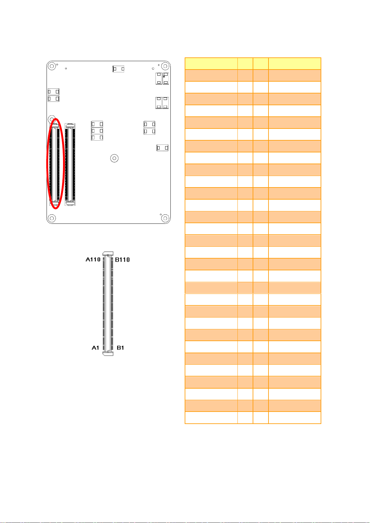
2.4.3 COM Express Connector 2 (CN1B)
ESM-CDV User’s Manual 29
Page 30

ESM-CDV User’s Manual
Signal
PIN
PIN
Signal
GND
C31
D31
GND
PCI_AD14
C32
D32
PCI_PAR
PCI_C/BE1#
C33
D33
PCI_SERR#
PCI_PERR#
C34
D34
PCI_STOP#
PCI_LOCK#
C35
D35
PCI_TRDY#
PCI_DEVSEL#
C36
D36
PCI_FRAME#
PCI_IRDY#
C37
D37
PCI_AD16
PCI_C/BE2#
C38
D38
PCI_AD18
PCI_AD17
C39
D39
PCI_AD20
PCI_AD19
C40
D40
PCI_AD22
GND
C41
D41
GND
PCI_AD21
C42
D42
PCI_AD24
PCI_AD23
C43
D43
PCI_AD26
PCI_C/BE3#
C44
D44
PCI_AD28
PCI_AD25
C45
D45
PCI_AD30
PCI_AD27
C46
D46
PCI_IRQC#
PCI_AD29
C47
D47
PCI_IRQD#
PCI_AD31
C48
D48
PCI_CLKRUN#
PCI_IRQA#
C49
D49
NC
PCI_IRQB#
C50
D50
PCI_CLK
GND
C51
D51
GND
NC
C52
D52
NC
NC
C53
D53
NC
NC
C54
D54
NC
NC
C55
D55
NC
NC
C56
D56
NC
NC
C57
D57
NC
NC
C58
D58
NC
NC
C59
D59
NC
GND
C60
D60
GND
30 ESM-CDV User’s Manual
Page 31

ESM-CDV User’s Manual
Signal
PIN
PIN
Signal
NC
C61
D61
NC
NC
C62
D62
NC
NC
C63
D63
NC
NC
C64
D64
NC-
NC
C65
D65
NC
NC
C66
D66
NC
NC
C67
D67
GND
NC
C68
D68
NC
NC
C69
D69
NC
GND
C70
D70
GND
NC
C71
D71
NC
NC
C72
D72
NC
NC
C73
D73
NC
NC
C74
D74
NC
NC
C75
D75
NC
GND
C76
D76
GND
NC
C77
D77
IDE_CBLID#
NC
C78
D78
NC
NC
C79
D79
NC
GND
C80
D80
GND
NC
C81
D81
NC
NC
C82
D82
NC
NC
C83
D83
NC
GND
C84
D84
GND
NC
C85
D85
NC
NC
C86
D86
NC
GND
C87
D87
GND
NC
C88
D88
NC
NC
C89
D89
NC
GND
C90
D90
GND
ESM-CDV User’s Manual 31
Page 32

ESM-CDV User’s Manual
Signal
PIN
PIN
Signal
NC
C91
D91
NC
NC
C92
D92
NC
GND
C93
D93
GND
NC
C94
D94
NC
NC
C95
D95
NC
GND
C96
D96
GND
NC
C97
D97
NC
NC
C98
D98
NC
NC
C99
D99
NC
GND
C100
D100
GND
NC
C101
D101
NC
NC
C102
D102
NC
GND
C103
D103
GND
VCC_12V
C104
D104
VCC_12V
VCC_12V
C105
D105
VCC_12V
VCC_12V
C106
D106
VCC_12V
VCC_12V
C107
D107
VCC_12V
VCC_12V
C108
D108
VCC_12V
VCC_12V
C109
D109
VCC_12V
GND
C110
D110
GND
32 ESM-CDV User’s Manual
Page 33

ESM-CDV User’s Manual
Signal
Signal Description
PCI_AD[0:31]
PCI bus multiplexed address and data lines.
PCI_C/BE[0:3]#
PCI bus byte enable lines, active low.
PCI_DEVSEL#
PCI bus Device Select, active low.
PCI_FRAME#
PCI bus Frame control line, active low.
PCI_IRDY#
PCI bus Initiator Ready control line, active low.
PCI_TRDY#
PCI bus Target Ready control line, active low.
PCI_STOP#
PCI bus STOP control line, active low, driven by cycle initiator.
PCI_PAR
PCI bus parity.
PCI_PERR#
Parity Error: An external PCI device drives PERR# when it receives data that has a
parity error.
PCI_REQ[0:3]#
PCI bus master request input lines, active low.
PCI_ GNT[0:3]#
PCI bus master grant output lines, active low.
PCI_RESET#
PCI Reset output, active low.
PCI_LOCK#
PCI Lock control line, active low.
PCI_SERR#
System Error: SERR# may be pulsed active by any PCI device that detects a system
error condition.
PCI_PME#
PCI Power Management Event: PCI peripherals drive PME# to wake system from
low-power states S1-S5.
PCI_CLKRUN#
Bidirectional pin used to support PCI clock run protocol for mobile systems.
PCI_IRQ[A:D]#
PCI interrupt request lines.
PCI_CLK
PCI 33MHz clock output.
Signal
Signal Description
IDE_D[0:15]
Bidirectional data to / from IDE device.
IDE_A[0:2]
Address lines to IDE device.
IDE_LOW#
I/O write line to IDE device.
Data latched on trailing (rising) edge.
IDE_IOR#
I/O read line to IDE device.
IDE_REQ
IDE Device DMA Request.
It is asserted by the IDE device to request a data transfer.
IDE_ACK#
IDE Device DMA Acknowledge.
2.4.3.1 Signal Description – COM Express Connector 2 (CN1B)
2.4.3.1.1 PCI Signals
2.4.3.1.2 IDE Signals
ESM-CDV User’s Manual 33
Page 34

ESM-CDV User’s Manual
IDE_CS1#
IDE Device Chip Select for 1F0h to 1FFh range.
IDE_CS3#
IDE Device Chip Select for 3F0h to 3FFh range.
IDE_IORDY
IDE device I/O ready input
Pulled low by the IDE device to extend the cycle.
IDE_RESET#
Reset output to IDE device, active low.
IDE_IRQ
Interrupt request from IDE device.
IDE_CBLID#
Input from off-Module hardware indicating the type of IDE cable being used.
34 ESM-CDV User’s Manual
Page 35

ESM-CDV User’s Manual
3.BIOS Setup
ESM-CDV User’s Manual 35
Page 36

ESM-CDV User’s Manual
3.1 Introduction
The BIOS setup program allows users to modify the basic system configuration. In this
following chapter will describe how to access the BIOS setup program and the
configuration options that may be changed.
3.2 Starting Setup
The AMI BIOS™ is immediately activated when you first power on the computer. The BIOS
reads the system information contained in the CMOS and begins the process of checking
out the system and configuring it. When it finishes, the BIOS will seek an operating system
on one of the disks and then launch and turn control over to the operating system.
While the BIOS is in control, the Setup program can be activated in one of two ways:
By pressing <Del> immediately after switching the system on, or
By pressing the <Del> key when the following message appears briefly at the bottom of the
screen during the POST (Power On Self Test).
Press DEL to enter SETUP
If the message disappears before you respond and you still wish to enter Setup, restart the
system to try again by turning it OFF then ON or pressing the "RESET" button on the
system case. You may also restart by simultaneously pressing <Ctrl>, <Alt>, and <Delete>
keys. If you do not press the keys at the correct time and the system does not boot, an error
message will be displayed and you will again be asked to.
Press F1 to Continue, DEL to enter SETUP
36 ESM-CDV User’s Manual
Page 37

ESM-CDV User’s Manual
Button
Description
↑
Move to previous item
↓
Move to next item
←
Move to the item in the left hand
→
Move to the item in the right hand
Esc key
Main Menu -- Quit and not save changes into CMOS
Status Page Setup Menu and Option Page Setup Menu -- Exit current page and
return to Main Menu
PgUp key
Increase the numeric value or make changes
PgDn key
Decrease the numeric value or make changes
+ key
Increase the numeric value or make changes
- key
Decrease the numeric value or make changes
F1 key
General help, only for Status Page Setup Menu and Option Page Setup Menu
F2 key
Previous Values.
F3 key
Optimized defaults
F4 key
Save & Exit Setup
3.3 Using Setup
In general, you use the arrow keys to highlight items, press <Enter> to select, use the
PageUp and PageDown keys to change entries, press <F1> for help and press <Esc> to
quit. The following table provides more detail about how to navigate in the Setup program
using the keyboard.
Navigating Through The Menu Bar
Use the left and right arrow keys to choose the menu you want to be in.
Note: Some of the navigation keys differ from one screen to another.
To Display a Sub Menu
Use the arrow keys to move the cursor to the sub menu you want. Then press
<Enter>. A “” pointer marks all sub menus.
ESM-CDV User’s Manual 37
Page 38

ESM-CDV User’s Manual
3.4 Getting Help
Press F1 to pop up a small help window that describes the appropriate keys to use and the
possible selections for the highlighted item. To exit the Help Window press <Esc> or
<Enter> key again.
3.5 In Case of Problems
If, after making and saving system changes with Setup, you discover that your computer no
longer is able to boot, the AMI BIOS supports an override to the CMOS settings which
resets your system to its defaults.
The best advice is to only alter settings which you thoroughly understand. To this end, we
strongly recommend that you avoid making any changes to the chipset defaults. These
defaults have been carefully chosen by both Award and your systems manufacturer to
provide the absolute maximum performance and reliability. Even a seemingly small change
to the chipset setup has the potential for causing you to use the override.
38 ESM-CDV User’s Manual
Page 39

ESM-CDV User’s Manual
3.6 BIOS setup
Once you enter the AMI BIOS CMOS Setup Utility, the Main Menu will appear on the
screen. The Main Menu allows you to select from several setup functions and exit choices.
Use the arrow keys to select among the items and press <Enter> to accept and enter the
sub-menu.
3.6.1 Main Menu
This section allows you to record some basic hardware configurations in your computer and
set the system clock.
ESM-CDV User’s Manual 39
Page 40

ESM-CDV User’s Manual
3.6.1.1 System Language
Use this option to select system language
3.6.1.2 System Date
Use the system time option to set the system time. Manually enter the hours, minutes and
seconds.
3.6.1.3 System Time
Use the system Date option to set the system date. Manually enter the day, month and
year.
Note: BIOS setup screens shown in this chapter are for reference only, and may
not exactly match what you see on your screen. Visit the Avalue website
(www.avalue.com.tw) to download the latest product and BIOS information.
40 ESM-CDV User’s Manual
Page 41

ESM-CDV User’s Manual
Item
Options
Description
Launch PXE OpROM
Disabled,
Enabled[Default]
Enable or Disable Boot Option for Legacy
Network Devices
Launch Storage OpROM
Disabled,
Enabled[Default]
Enable or Disable Boot Option for Legacy
Mass Storage Devices with Option ROM.
3.6.2 Advanced BIOS settings
This section allows you to configure your CPU and other system devices for basic operation
through the following sub-menus.
3.6.2.1 PCI Subsystem Settings
ESM-CDV User’s Manual 41
Page 42

ESM-CDV User’s Manual
Item
Options
Description
PCI Latency Timer
32 PCI Bus Clocks[Default]
64 PCI Bus Clocks
96 PCI Bus Clocks
128 PCI Bus Clocks
160 PCI Bus Clocks
192 PCI Bus Clocks
224 PCI Bus Clocks
248 PCI Bus Clocks
Value to be programmed into PCI Latency
Timer Register.
VGA Palette Snoop
Disabled[Default],
Enabled
Enables or Disables VGA Palette Registers
Snooping.
PERR# Generation
Disabled[Default],
Enabled
Enables or Disables PCI Device to Generate
PERR#
SERR# Generation
Disabled[Default],
Enabled
Enables or Disables PCI Device to Generate
SERR#
Item
Options
Description
Enable ACPI Auto Configuration
Disabled,
Enabled[Default]
Enables or Disables BIOS ACPI Auto
Configuration.
Enable Hibernation
Disabled,
Enabled[Default]
Enables or Disables System ability to
Hibernate (OS/S4 Sleep State). This
option may be not effective with some
OS.
ACPI Sleep State
Suspend Disabled
S1 (CPU Stop Clock)
S3 (Suspend to RAM) [Default]
Select the highest ACPI sleep state
the system will enter when the
SUSPEND button is pressed.
Lock Legacy Resources
Disabled[Default],
Enabled
Enables or Disables Lock of Legacy
Resources.
S3 Video Repost
Disabled[Default],
Enabled
Enable or Disable S3 Video Repost
3.6.2.2 ACPI Settings
You can use this item to set up ACPI Configuration.
42 ESM-CDV User’s Manual
Page 43

ESM-CDV User’s Manual
Item
Options
Description
Wake system with Fixed Time
Disabled[Default],
Enabled
Enables or disables wake on alarm event.
When enabled, System will wake on the
hr::min::sec specified.
Wake system with Dynamic Time
Disabled[Default],
Enabled
Enables or Disables wake on alarm event.
When enabled, System will wake on the
current time + Increase minutes(s).
3.6.2.3 S5 RTC Wake Settings
3.6.2.4 CPU Configuration
Use the CPU configuration menu to view detailed CPU specification and configure the
CPU.
ESM-CDV User’s Manual 43
Page 44

ESM-CDV User’s Manual
Item
Options
Description
Hyper-Threading
Disabled
Enabled[Default]
Enabled for Windows XP and Linux (OS
optimized for Hyper-Technology) and Disabled
for other OS (OS not optimized for
Hyper-Threading Technology).
Execute Disable Bit
Disabled
Enabled[Default]
XD can prevent certain classed of malicious
buffer overflow attacks when combined with a
supporting OS (Windows Server 2003 SP1,
Windows XP SP2, SuSE Linux 9.2, RedHat
Enterprise 3 Update 3.)
Limit CPUID Maximum
Disabled[Default],
Enabled
Disabled for Windows XP.
3.6.2.5 Thermal Configuration
44 ESM-CDV User’s Manual
Page 45

ESM-CDV User’s Manual
Item
Options
Description
DTS SMM
Disabled[Default]
Enabled
Critical Temp Reporting (Out of Spec)
Disabled: ACPI thermal management uses EC
reported temperature values.
Enabled: ACPI thermal management uses
DTS SMM mechanism to obtain CPU
temperature values.
Out of spec: ACPI thermal management uses
EC reported temperature values and DTS
SMM is used to handle Out of spec condition.
3.6.2.5.1 CPU Thermal Configuration
ESM-CDV User’s Manual 45
Page 46

ESM-CDV User’s Manual
Item
Options
Description
Critical Trip Point
POR[Default]
15C
23C
31C
39C
47C
55C
63C
71C
79C
87C
95C
103C
111C
119C
127C
This value controls the temperature of the
ACPI Critical Trip Point – the point in which the
OS will shut the system off. NOTE: 100C is the
Plan Of Record (POR) for all Intel mobile
Passive Trip Point
Disabled
15C
23C
31C
39C
47C
55C
63C
71C
79C
87C
95C[Default]
103C
111C
119C
This value controls the temperature of the
ACPI Passive Trip Point - the point in which
the OS will begin throttling the processor.
3.6.2.5.2 Platform Thermal Configuration
46 ESM-CDV User’s Manual
Page 47

ESM-CDV User’s Manual
Passive TC1 Value
1 – 16
This value sets the TC1 -2 value for the ACPI
Passive Cooling Formula. Range 1 – 16.
Passive TC2 Value
Passive TSP Value
2 - 32
This item sets the TSP value for the ACPI
Passive Cooling Formula. It represents in
tenths of a second how often the OS will read
the temperature when passive cooling is
enabled Range 2- 32
Item
Options
Description
SATA Controller(s)
Disabled,
Enabled[Default]
SATA Ports (0-3) Device Names if Present
and Enabled.
Configure SATA as
IDE[Default]
AHCI
Select a configuration for SATA Controller
3.6.2.6 IDE Configuration
ESM-CDV User’s Manual 47
Page 48

ESM-CDV User’s Manual
Item
Options
Description
iFFS Support
Disabled[Default],
Enabled
Enable or Disable iFFS
3.6.2.7 Intel Fast Flash Standby
3.6.2.8 USB Configuration
The USB configuration menu is used to read USB configuration information and configure
USB.
48 ESM-CDV User’s Manual
Page 49

ESM-CDV User’s Manual
Item
Options
Description
Legacy USB support
Enabled[Default]
Disabled
Auto
Enables Legacy USB support.
AUTO option disables legacy support if no USB
devices are connected. DISABLE will keep USB
devices available only for EFI applications.
ECHI Hand-off
Disabled[Default]
Enabled
This is a workaround for OSes without EHCI hand-off
support. The EHCI ownership change should be
claimed by EHCI driver.
USB transfer time-out
1sec / 5sec
10sec /
20sec[Default]
The time-out value for Control, Bulk, and Interrupt
transfers.
Device reset time-out
10sec /
20sec[Default]
30sec / 40sec
USB mass storage device Start Unit command
time-out.
Device power-up delay
Auto[Default]
Manual
Maximum time the device will take before it properly
reports itself to the Host Controller. “Auto” uses
default value: for a Root port it is 100ms, for a Hub
port the delay is taken from Hub descriptor.
Mass Storage Devices
Auto[Default]
Floppy
Forced FDD
Hard Disk
CD-ROM
Mass storage device emulation type. “AUTO”
enumerates devices less than 530MB as floppies.
Forced FDD option can be used to force HDD
formatted drive to boot as FDD (e.g. ZIP drive).
3.6.2.9 H/W Monitor
The H/W Monitor shows the operating temperature, fan speeds and system voltages.
ESM-CDV User’s Manual 49
Page 50

ESM-CDV User’s Manual
Item
Options
Description
Smart Self Test
Disabled[Default]
Enabled
Run SMART Self Test on all HDDs during POST
3.6.2.10 Smart Settings
3.6.2.11 Super IO Configuration
You can use this item to set up or change the Super IO configuration for FDD controllers,
parallel ports and serial ports. Please refer to 3.6.2.11.1, 3.6.2.11.2, 3.6.2.11.3 and
3.6.2.11.4 for more information.
50 ESM-CDV User’s Manual
Page 51

ESM-CDV User’s Manual
Item
Option
Description
Deep S5
Disabled[Default]
Enabled
Deep S5 for power saving
Restore AC Power Loss
Power Off[Default]
Power On
Last State
Specify what state to go to when
power is re-applied after a power
failure (G3 state).
Item
Option
Description
Floppy Disk Controller
Disabled
Enabled[Default]
Enable or Disable Floppy
Disk Controller.
Change Settings
Auto[Default]
IO=3F0h; IRQ=6; DMA=2;
IO=3F0h; IRQ=3,4,5,6,7,10,11,12; DMA=2,3;
IO=370h; IRQ=3,4,5,6,7,10,11,12; DMA=2,3;
Select an optimal setting
for Super IO device.
Device Mode
Read Write[Default]
Write Protect
Change mode of Floppy
Controller. Select ‘Read
Write’ for normal operation.
Select ‘Write Protect’ mode
for read only operation.
3.6.2.11.1 Floppy Disk Controller Configuration
ESM-CDV User’s Manual 51
Page 52

ESM-CDV User’s Manual
Item
Option
Description
Serial Port
Disabled
Enabled[Default]
Enable or Disable the Serial Port
(COM).
Change Settings
Auto[Default]
IO=3F8h; IRQ=4;
IO=3F8h; IRQ=3,4,5,6,7,10,11,12;
IO=2F8h; IRQ=3,4,5,6,7,10,11,12;
IO=3E8h; IRQ=3,4,5,6,7,10,11,12;
IO=2E8h; IRQ=3,4,5,6,7,10,11,12;
Select an optimal setting for
Super IO device.
3.6.2.11.2 Serial Port 0 Configuration
52 ESM-CDV User’s Manual
Page 53

ESM-CDV User’s Manual
Item
Option
Description
Serial Port
Disabled
Enabled[Default]
Enable or Disable Serial Port
(COM).
Change Settings
Auto[Default]
IO=2F8h; IRQ=3,
IO=3F8h; IRQ=3,4,5,6,7,10,11,12
IO=2F8h; IRQ=3,4,5,6,7,10,11,12
IO=3E8h; IRQ=3,4,5,6,7,10,11,12
IO=2E8h; IRQ=3,4,5,6,7,10,11,12
Select an optimal setting for
Super IO device.
Device Mode
Standard Serial Port Mode[Default]
IrDA 1 .0(HP SIR) Mode
ASKIR Mode
Change the Serial Port mode.
Select <High Speed> or <Normal
mode> mode.
UART 232 422 485
UART 232, [Default]
UART 422,
UART 485
Change the Serial Port as
RS232/422/485.
3.6.2.11.3 Serial Port 1 Configuration
ESM-CDV User’s Manual 53
Page 54

ESM-CDV User’s Manual
Item
Option
Description
Parallel Port
Disabled
Enabled[Default]
Enable or Disable Parallel Port
(LPT/LPTE).
Change Settings
Auto[Default]
IO=378h; IRQ=5,
IO=378h; IRQ=5,6,7,10,11,12
IO=278h; IRQ=5,6,7,10,11,12
IO=3BCh; IRQ=5,6,7,10,11,12
IO=378h;
IO=278h;
IO=3BCh;
Select an optimal setting for
Super IO device.
Device Mode
STD Printer Mode[Default]
SPP Mode
EPP-1.9 and SPP Mode
EPP-1.7 and SPP Mode
ECP Mode
ECP and EPP 1.9 Mode
ECP and EPP 1.7 Mode
Change the Printer Port mode.
3.6.2.11.4 Parallel Port Configuration
54 ESM-CDV User’s Manual
Page 55

ESM-CDV User’s Manual
Item
Option
Description
EIST
Disabled
Enabled[Default]
Enable/Disable Intel SpeedStep.
CPU C state Report
Disabled[Default]
Enabled
Enable/Disable CPU C State
report to OS.
3.6.2.12 PPM configuration
3.6.3 Advanced Chipset Features
ESM-CDV User’s Manual 55
Page 56

ESM-CDV User’s Manual
Item
Option
Description
MRC Fast Boot
Disabled
Enabled[Default]
Enable or Disable MRC fast boot
Max TOLUD
Dynamic[Default]
1GB
1.25 GB
Maximum Value of TOLUD.
Dynamic assignment would adjust
TOLUD automatically based on
3.6.3.1 Host bridge
3.6.3.1.1 Memory Frequency and Timing
56 ESM-CDV User’s Manual
Page 57

ESM-CDV User’s Manual
1.5 GB
1.75 GB
2 GB
2.25 GB
2.5 GB
2.75 GB
3 GB
3.25 GB
largest MMIO length of installed
graphic controller.
Item
Option
Description
VBIOS Version
1071 eDP-LVDS[Default]
1085 eDP-LVDS
EMGD (A813)
Select the VBIOS version
IGFX - Boot Type
VBIOS Default[Default]
CRT,
CRT+LVDS,
LVDS,
LVDS+CRT,
Select the Video Device which will
be activated during POST. This
has no effect if external graphics
present.
Panel Scaling
Auto[Default]
Force Scaling
Off
Maintain Aspect Ratio
Select the LCD panel scaling
option used by the Internal
Graphics Device.
Active LFP
No LVDS
Int-LVDS (eDP-7511) [Default]
Select the Active LFP
Configuration.
No LVDS: VBIOS does not enable
LVDS.
Int-LVDS: VBIOS enables LVDS
driver by integrated encoder.
SDVO LVDS: VBIOS enables
LVDS driver by SDVO encoder.
eDP Port-A: LFP Driven by
Int-DisplayPort encoder from
3.6.3.1.2 Intel IGD Configuration
ESM-CDV User’s Manual 57
Page 58

ESM-CDV User’s Manual
Port-A.
eDP Port-D: LFP Driven by
Int-DisplayPort encoder from
Port-D (through PCH).
CH7511 EDID Panel Option
1024x768 24/1[Default]
800x600 18/1
1024x768 18/1
1366x768 18/1
1024x600 18/1
1280x800 18/1
1920x1200 24/2
640x480 18/1
800x480 18/1
1920x1080 18/2
1280x1024 24/2
1440x900 18/2
1600x1200 24/2
1366x768 24/1
1920x1080 24/2
1680x1050 24/2
Port1-EDP to LVDS (Chrotel
7511) Panel EDID Option.
LVDS Back Light PWM
00%
25%
50%[Default]
75%
100%
Select LVDS back light PWM duty
LVDS Back Light PWM
Frequency
128Hz
205Hz[Default]
340Hz
512Hz
1KHz
2KHz
3KHz
5KHz
10KHz
13KHz
26KHz
65KHz
130KHz
Select LVDS back light PWM
Frequency
IGD Clock Source
External clock[Default]
Internal clock
IGD clock selection
Fixed Graphics Memory Size
128MB[Default]
256MB
Configure Fixed Graphics
Memory Size
ALS Support
Enabled
Disabled[Default]
Valid only for ACPI.
Legacy=ALS Support through the
IGD INT10 function.
ACPI=ALS support through an
ACPI ALS driver
58 ESM-CDV User’s Manual
Page 59

ESM-CDV User’s Manual
Item
Option
Description
DMI Link ASPM Control
Disabled
Enabled[Default]
The control of Active State Power
Management on both NB side and
SB side of the DMI Link.
PCI-Exp. High Priority Port
Disabled[Default]
Port0
Port1
Port2
Port3
Select a PCI Express High Priority
Port.
High Precision Timer
Disabled
Enabled[Default]
Enable or Disable the High
Precision Event Timer.
SLP_S4 Assertion Width
1-2 Seconds[Default]
2-3 Seconds
3-4 Seconds
4-5 Seconds
Select a minimum assertion width
of the SLP_S4# signal.
3.6.3.2 South bridge
ESM-CDV User’s Manual 59
Page 60

ESM-CDV User’s Manual
Item
Option
Description
Azalia Controller
Disabled
HD Audio[Default]
Azalia Controller.
Select USB Mode
By Ports
By controllers[Default]
Select USB mode to control USB
ports.
UHCI #1 (ports 0 and 1)
Disabled
Enabled[Default]
Control the USB UHCI (USB1.1)
functions. Disable from highest to
lowest controller.
UHCI #2 (ports 2 and 3)
Disabled
Enabled[Default]
UHCI #3 (ports 4 and 5)
Disabled
Enabled[Default]
UHCI #4 (ports 6 and 7)
Disabled
Enabled[Default]
USB 2.0(EHCI) Support
Disabled
Enabled[Default]
Enable or Disable USB 2.0
(EHCI) Support.
SMBus Controller
Disabled
Enabled[Default]
Enable or Disable OnChip SMBus
Controller.
SIRQ Logic
Disabled
Enabled[Default]
Enable or Disable SIRQ logic
SIRQ Mode
Quiet
Continous[Default]
Set SIRQ mode.
3.6.3.2.1 TPT Devices
60 ESM-CDV User’s Manual
Page 61

ESM-CDV User’s Manual
Item
Option
Description
PCI Express Port 0
Disabled
Enabled[Default]
Enable / Disable PCI Express
Root Port 0.
Port 0 IOxAPIC
Disabled[Default]
Enabled
Enable / Disable PCI Express
Root Port 0 I/O APIC.
Automatic ASPM
Manual[Default]
Auto
Automatically enable ASPM
based on reported capabilities
and known issues.
ASPM L0s
Disabled[Default]
Root Port Only
Endpoint Port Only
Both Root And Endpoint Ports
Enable PCIe ASPM L0s.
ASPM L1
Disabled[Default]
Enabled
Enable PCIe ASPM L1.
URR
Disabled[Default]
Enabled
PCI Express Unsupported
Request Reporting
Enable/Disable.
FER
Disabled[Default]
Enabled
PCI Express Device Fatal Error
Reporting Enable/Disable.
NFER
Disabled[Default]
Enabled
PCI Express Device Non-Fatal
Error Reporting Enable/Disable.
CER
Disabled[Default]
Enabled
PCI Express Device Correctable
Error Reporting Enable/Disable.
CTO
Disabled[Default]
Enabled
PCI Express Completion Timer
TO Enable/Disable.
SEFE
Disabled[Default]
Enabled
Root PCI Express System Error
on Fatal Error Enable/Disable
SENFE
Disabled[Default]
Enabled
Root PCI Express System Error
on Non-Fatal Error
Enable/Disable
SECE
Disabled[Default]
Root PCI Express Error on
3.6.3.2.2 PCI Express Root Port 0
ESM-CDV User’s Manual 61
Page 62

ESM-CDV User’s Manual
Enabled
Correctable Error Enable/Disable
PME SCI
Disabled
Enabled[Default]
PCI Express PME SCI
Enable/Disable.
Hot Plug
Disabled[Default]
Enabled
PCI Express Hot Plug
Enable/Disable
Extra Bus Reserved
0 - 7
Extra Bus Reserved (0-7)for
bridges behind this Root Bridge.
Reserved Memory
1 – 20MB
Reserved Memory and
Prefetchable Memory (1-20MB)
Range for this Root Bridge.
Reserved I/O
4K/8K/12K/16K/20K
Reserved I/O
(4K/8K/12K/16K/20K) Range for
this Root Bridge.
3.6.3.2.3 PCI Express Root Port 1/2/3
62 ESM-CDV User’s Manual
Page 63

ESM-CDV User’s Manual
Item
Option
Description
PCI Express Port 1/2/3
Auto[Default]
Enabled
Disabled
Enable / Disable PCI Express
Root Port 1/2/3.
Port 0 IOxAPIC
Disabled[Default]
Enabled
Enable / Disable PCI Express
Root Port 0 I/O APIC.
Automatic ASPM
Manual[Default]
Auto
Automatically enable ASPM
based on reported capabilities
and known issues.
ASPM L0s
Disabled[Default]
Root Port Only
Endpoint Port Only
Both Root And Endpoint Ports
Enable PCIe ASPM L0s.
ASPM L1
Disabled[Default]
Enabled
Enable PCIe ASPM L1.
URR
Disabled[Default]
Enabled
PCI Express Unsupported.
Request Reporting
Enable/Disable.
FER
Disabled[Default]
Enabled
PCI Express Device Fatal Error
Reporting Enable/Disable.
NFER
Disabled[Default]
Enabled
PCI Express Device Non-Fatal
Error Reporting Enable/Disable.
CER
Disabled[Default]
Enabled
PCI Express Device Correctable
Error Reporting Enable/Disable.
CTO
Disabled[Default]
Enabled
PCI Express Completion Timer
TO Enable/Disable.
SEFE
Disabled[Default]
Enabled
Root PCI Express System Error
on Fatal Error Enable/Disable.
SENFE
Disabled[Default]
Enabled
Root PCI Express System Error
on Non-Fatal Error
Enable/Disable.
SECE
Disabled[Default]
Enabled
Root PCI Express Error on
Correctable Error Enable/Disable.
PME SCI
Disabled
Enabled[Default]
PCI Express PME SCI
Enable/Disable.
Hot Plug
Disabled[Default]
PCI Express Hot Plug
ESM-CDV User’s Manual 63
Page 64

ESM-CDV User’s Manual
Enabled
Enable/Disable.
Extra Bus Reserved
0 - 7
Extra Bus Reserved (0 -7)for
bridges behind this Root Bridge.
Reserved Memory
1 – 20MB
Reserved Memory and
Prefetchable Memory (1-20MB)
Range for this Root Bridge.
Reserved I/O
4K/8K/12K/16K/20K
Reserved I/O
(4K/8K/12K/16K/20K) Range for
this Root Bridge.
Item
Option
Description
Setup Prompt Timeout
1~65535
Number of seconds to wait for
setup activation key.
65535(0xFFFF) means indefinite
waiting.
Bootup NumLock State
On[Default]
Off
Select the keyboard NumLock
state
Quiet Boot
Disabled[Default]
Enabled
Enables or disables Quiet Boot
option
Fast Boot
Disabled[Default]
Enabled
Enables or disables boot with
initialization of a minimal set of
devices required to launch active
boot option. Has no effect for BBS
boot options
GateA20 Active
Upon Request[Default]
Always
UPON REQUEST – GA20 can be
disabled using BIOS services.
ALWAYS - do not allow disabling
GA20; this option is useful when
any RT code is executed above
1MB
Option ROM Messages
Force BIOS[Default]
Keep Current
Set display mode for Option ROM
3.6.4 Boot settings
64 ESM-CDV User’s Manual
Page 65

ESM-CDV User’s Manual
INT19 Trap Response
Immediate[Default]
Postponed
BIOS reaction on INT19 ttapping
by Option ROM: IMMEDIATE –
execute the trap right away;
POSTPONED – execute the trap
during legacy boot.
CSM Support
Disabled
Enabled[Default]
Auto
Enable/Disable CSM Support. If
Auto is selected, based on OS,
CSM will be enabled/disabled
automatically.
Boot Option #1/2/3
Sets the system boot order
3.6.5 Security
Use the Security menu to set system and user password.
3.6.5.1 Administrator Password
This setting specifies a password that must be entered to access the BIOS Setup Utility. If
only the Administrator's password is set, then this only limits access to the BIOS setup
program and is only asked for when entering the BIOS setup program. By default, no
password is specified.
3.6.5.2 User Password
This setting specifies a password that must be entered to access the BIOS Setup Utility or
to boot the system. If only the User's password is set, then this is a power on password and
must be entered to boot or enter the BIOS setup program. In the BIOS setup program, the
User will have Administrator rights. By default, no password is specified.
ESM-CDV User’s Manual 65
Page 66

ESM-CDV User’s Manual
3.6.6 Save & Exit
3.6.6.1 Save Changes and Exit
Use the save changes and reset option to save the changes made to the BIOS options and
to exit the BIOS configuration setup program.
3.6.6.2 Discard Changes and Exit
Use the Discard changes and Exit option to exit the system without saving the changes
made to the BIOS configuration setup program.
66 ESM-CDV User’s Manual
Page 67

ESM-CDV User’s Manual
3.6.6.3 Save Changes and Reset
Any changes made to BIOS settings are stored in NVRAM. The setup program then exits
and reboots the controller.
3.6.6.4 Discard Changes and Reset
Any changes made to BIOS settings during this session of the BIOS setup program are
discarded. The setup program then exits and reboots the controller.
3.6.6.5 Save Changes
Changes made to BIOS settings during this session are committed to NVRAM. The setup
program remains active, allowing further changes.
3.6.6.6 Discard Changes
Any changes made to BIOS settings during this session of the BIOS setup program are
discarded. The BIOS setup continues to be active.
3.6.6.7 Restore Defaults
This option restores all BIOS settings to the factory default. This option is useful if the
controller exhibits unpredictable behavior due to an incorrect or inappropriate BIOS setting.
3.6.6.8 Save as User Defaults
This option saves a copy of the current BIOS settings as the User Defaults. This option is
useful for preserving custom BIOS setup configurations.
3.6.6.9 Restore User Defaults
This option restores all BIOS settings to the user defaults. This option is useful for restoring
previously preserved custom BIOS setup configurations.
3.6.6.10 Boot override
This option lists all possible bootable devices and allows the user to override the Boot
Option Priorities list for the current boot. If no changes have been made to the BIOS setup
options, the system will continue booting to the selected device without first rebooting. If
BIOS setup options have been changed and saved, a reboot will be required and the boot
override selection will not be valid.
ESM-CDV User’s Manual 67
Page 68

ESM-CDV User’s Manual
4. Drivers Installation
Note: Installation procedures and screen shots in this section are
for your reference and may not be exactly the same as
shown on your screen.
68 ESM-CDV User’s Manual
Page 69

ESM-CDV User’s Manual
Insert the Supporting DVD-ROM to
DVD-ROM drive, click on “start” icon and it
should show the index page of Avalue’s
products automatically. If not, locate the
folder HTML and choose the product from
the targeted folder.
Note: The installation procedures and
screen shots in this section are
based on W7 operating system.
Step 1. Locate 「\VGA\ESM-CDV_VGA」.
Step 4. Select Next to continue
installation.
Step 2. Select Next to start setup.
Step 5. Select Next to continue installation.
Step 3. Select Yes to the next step.
Step 6. Select Finish to complete
installation
4.1 Install VGA Driver
ESM-CDV User’s Manual 69
Page 70

ESM-CDV User’s Manual
Insert the Supporting DVD-ROM to DVD-ROM
drive, click on “start” icon and it should show
the index page of Avalue’s products
automatically. If not, locate the folder HTML
and choose the product from the targeted
folder.
Note: The installation procedures and screen
shots in this section are based on W7
operating system.
Step 3. Click Next to accept licence
agreement.
Step 1. Locate
「\Driver_Gigabit\Intel\82574L\ESM-CDV_LA
N」
Step 4. Click Next after selecting
programs to install.
Step 2. Click Next.
Step 5. Click Install to begin installation
4.2 Install Ethernet Driver (For Intel 82574L)
70 ESM-CDV User’s Manual
Page 71

ESM-CDV User’s Manual
Step 6. Click Finish to complete installation.
ESM-CDV User’s Manual 71
Page 72

ESM-CDV User’s Manual
Insert the Supporting DVD-ROM to
DVD-ROM drive, click on “start” icon and it
should show the index page of Avalue’s
products automatically. If not, locate the
folder HTML and choose the product from
the targeted folder.
Note: The installation procedures and
screen shots in this section are
based on W7 operating system.
Step 3. Click Next.
Step 1. Locate
「\Driver_Chipset\Intel\ESM-CDV_INF」
Step 4. Select Yes to the next step.
Step 2. Wait while the following setup files
are extracted. .
Step 5. Click Next.
4.3 Install Chipset Driver
72 ESM-CDV User’s Manual
Page 73

ESM-CDV User’s Manual
Step 6. Click Next to complete installation.
Step 7. Click Finish to complete installation.
ESM-CDV User’s Manual 73
Page 74

ESM-CDV User’s Manual
5. Mechanical Drawing
74 ESM-CDV User’s Manual
Page 75

ESM-CDV User’s Manual
Unit: mm
ESM-CDV User’s Manual 75
Page 76

ESM-CDV User’s Manual
Unit: mm
76 ESM-CDV User’s Manual
 Loading...