


Avalue ERX-Q77 User Manual

ERX-Q77
Intel® Q77 with Core™ i7/ i5 /i3 Micro-ATX Motherboard
User’s Manual
1st Ed – 27 November 2012
Part No. E2047XQ7700R

ERX-Q77 User’s Manual
FCC Statement
Notice
Copyright Notice
Trademark Acknowledgement
Disclaimer
THIS DEVICE COMPLIES WITH PART 15 FCC RULES. OPERATION IS
SUBJECT TO THE FOLLOWING TWO CONDITIONS:
(1) THIS DEVICE MAY NOT CAUSE HARMFUL INTERFERENCE.
(2) THIS DEVICE MUST ACCEPT ANY INTERFERENCE RECEIVED INCLUDING
INTERFERENCE THAT MAY CAUSE UNDESIRED OPERATION.
THIS EQUIPMENT HAS BEEN TESTED AND FOUND TO COMPLY WITH THE LIMITS
FOR A CLASS "A" DIGITAL DEVICE, PURSUANT TO PART 15 OF THE FCC RULES.
THESE LIMITS ARE DESIGNED TO PROVIDE REASONABLE PROTECTION AGAINST
HARMFUL INTERFERENCE WHEN THE EQUIPMENT IS OPERATED IN A COMMERCIAL
ENVIRONMENT. THIS EQUIPMENT GENERATES, USES, AND CAN RADIATE RADIO
FREQUENCY ENERGY AND, IF NOT INSTALLED AND USED IN ACCORDANCE WITH
THE INSTRUCTION MANUAL, MAY CAUSE HARMFUL INTERFERENCE TO RADIO
COMMUNICATIONS.
OPERATION OF THIS EQUIPMENT IN A RESIDENTIAL AREA IS LIKELY TO CAUSE
HARMFUL INTERFERENCE IN WHICH CASE THE USER WILL BE REQUIRED TO
CORRECT THE INTERFERENCE AT HIS OWN EXPENSE.
This guide is designed for experienced users to setup the system within the shortest time. For
detailed information, please always refer to the electronic user's manual.
Copyright 2012 Avalue Technology Inc., ALL RIGHTS RESERVED.
No part of this document may be reproduced, copied, translated, or transmitted in any form or
by any means, electronic or mechanical, for any purpose, without the prior written permission
of the original manufacturer.
Brand and product names are trademarks or registered trademarks of their respective
owners.
Avalue Technology Inc. reserves the right to make changes, without notice, to any product,
including circuits and/or software described or contained in this manual in order to improve
design and/or performance. Avalue Technology assumes no responsibility or liability for the
use of the described product(s), conveys no license or title under any patent, copyright, or
masks work rights to these products, and makes no representations or warranties that these
2 ERX-Q77 User’s Manual

ERX-Q77 User’s Manual
3
Life Support Policy
A Message to the Customer
products are free from patent, copyright, or mask work right infringement, unless otherwise
specified. Applications that are described in this manual are for illustration purposes only.
Avalue Technology Inc. makes no representation or warranty that such application will be
suitable for the specified use without further testing or modification.
Avalue Technology’s PRODUCTS ARE NOT FOR USE AS CRITICAL COMPONENTS IN
LIFE SUPPORT DEVICES OR SYSTEMS WITHOUT THE PRIOR WRITTEN APPROVAL
OF Avalue Technology Inc.
As used herein:
1. Life support devices or systems are devices or systems which, (a) are intended for surgical
implant into body, or (b) support or sustain life and whose failure to perform, when properly
used in accordance with instructions for use provided in the labeling, can be reasonably
expected to result in significant injury to the user.
2. A critical component is any component of a life support device or system whose failure to
perform can be reasonably expected to cause the failure of the life support device or
system, or to affect its safety or effectiveness.
Avalue Customer Services
Each and every Avalue’s product is built to the most exacting specifications to ensure reliable
performance in the harsh and demanding conditions typical of industrial environments.
Whether your new Avalue device is destined for the laboratory or the factory floor, you can be
assured that your product will provide the reliability and ease of operation for which the name
Avalue has come to be known.
Your satisfaction is our primary concern. Here is a guide to Avalue’s customer services. To
ensure you get the full benefit of our services, please follow the instructions below carefully.
Technical Support
We want you to get the maximum performance from your products. So if you run into
technical difficulties, we are here to help. For the most frequently asked questions, you can
easily find answers in your product documentation. These answers are normally a lot more
detailed than the ones we can give over the phone. So please consult the user’s manual first.
To receive the latest version of the user’s manual; please visit our Web site at:
http://www.avalue.com.tw/
ERX-Q77 User’s Manual

ERX-Q77 User’s Manual
Headquarters and Branch
Avalue USA
Avalue Technology Inc.
7F, 228, Lian-cheng Road, Chung Ho City, Taipei,
Taiwan
Tel:+886-2-8226-2345
Fax: +886-2-8226-2777
Information:sales@avalue.com.tw
Service: service@avalue.com.tw
Avalue Technology Inc.
9 Timber Lane, Marlboro, NJ 07746-1443
Tel: (732) 414-6500
Fax: (732) 414-6501
Information: sales@avalue-usa.com
Service: support@avalue-usa.com
BCM Advanced Research
Avalue Europe
BCM Advanced Research
an Avalue Company
7 Marconi, Irvine, CA92618
Tel: +1-949-470-1888
Fax: +1-949-470-0971
Information: BCMSales@bcmcom.com
Web: www.bcmcom.com
Avalue Europe A/S
Moelledalen 22C, 3140
Aalsgaarde, Denmark
Tel: +45-7025-0310
Fax:+45-4975-5026
Information: sales.europe@avalue.com.tw
Service: service.europe@avalue.com.tw
Avalue China
Avalue Japan
Avalue Technology Inc.
Room 805, Building 9,No.99 Tianzhou Rd.,
Caohejing Development Area,
Xuhui District, Shanghai
Tel: +86-21-5169-3609
Fax:+86-21-5445-3266
Information: sales.china@avalue.com.cn
Service: service@avalue.com.tw
Avalue Technology Inc.
3F Ishiyama-Bldg, 1-6-1 Taito,
Taito-Ku, Tokyo 110-0016 Japan
Tel: +81-3-5807-2321
Fax: +81-3-5807-2322
Information: sales.japan@avalue.com.tw
Service: service@avalue.com.tw
If you still cannot find the answer, gather all the information or questions that apply to your
problem, and with the product close at hand, call your dealer. Our dealers are well trained
and ready to give you the support you need to get the most from your Avalue’s products. In
fact, most problems reported are minor and are able to be easily solved over the phone.
In addition, free technical support is available from Avalue’s engineers every business day.
We are always ready to give advice on application requirements or specific information on the
installation and operation of any of our products. Please do not hesitate to call or e-mail us.
4 ERX-Q77 User’s Manual

ERX-Q77 User’s Manual
5
Product Warranty
Avalue warrants to you, the original purchaser, that each of its products will be free from
defects in materials and workmanship for two years from the date of purchase.
This warranty does not apply to any products which have been repaired or altered by persons
other than repair personnel authorized by Avalue, or which have been subject to misuse,
abuse, accident or improper installation. Avalue assumes no liability under the terms of this
warranty as a consequence of such events. Because of Avalue’s high quality-control
standards and rigorous testing, most of our customers never need to use our repair service. If
any of Avalue’s products is defective, it will be repaired or replaced at no charge during the
warranty period. For out-of-warranty repairs, you will be billed according to the cost of
replacement materials, service time, and freight. Please consult your dealer for more details.
If you think you have a defective product, follow these steps:
1. Collect all the information about the problem encountered. (For example, CPU type and
speed, Avalue’s products model name, hardware & BIOS revision number, other
hardware and software used, etc.) Note anything abnormal and list any on-screen
messages you get when the problem occurs.
2. Call your dealer and describe the problem. Please have your manual, product, and any
helpful information available.
3. If your product is diagnosed as defective, obtain an RMA (return material authorization)
number from your dealer. This allows us to process your good return more quickly.
4. Carefully pack the defective product, a complete Repair and Replacement Order Card
and a photocopy proof of purchase date (such as your sales receipt) in a shippable
container. A product returned without proof of the purchase date is not eligible for
warranty service.
5. Write the RMA number visibly on the outside of the package and ship it prepaid to your
dealer.
ERX-Q77 User’s Manual

ERX-Q77 User’s Manual
Contents
1. Getting Started ............................................................................................................... 9
1.1 Safety Precautions ....................................................................................................... 9
1.2 Packing List .................................................................................................................. 9
1.3 Document Amendment History .................................................................................. 10
1.4 Manual Objectives ...................................................................................................... 11
1.5 System Specifications ................................................................................................ 12
1.6 Architecture Overview – Block Diagram ..................................................................... 14
2. Hardware Configuration .............................................................................................. 15
2.1 Product Overview ....................................................................................................... 16
2.1.1 Platform Features and Benefits ........................................................................................................ 16
2.1.2 Key Architecture Features ................................................................................................................ 17
2.2 Before you Proceed .................................................................................................... 18
2.3 Motherboard Overview ............................................................................................... 19
2.3.1 Placement direction .......................................................................................................................... 19
2.3.2 Screw Holes ..................................................................................................................................... 19
2.3.3 Motherboard Layout ......................................................................................................................... 20
2.4 Jumper and Connector List ........................................................................................ 21
2.4.1 Internal Connectors ............................................................................................................................ 22
2.5 Central Processing Unit (CPU) ................................................................................... 23
2.5.1 Installing the CPU............................................................................................................................. 24
2.5.2 Installing the CPU Heatsink and Fan ............................................................................................... 26
2.5.3 Uninstalling the CPU Heatsink and Fan ........................................................................................... 28
2.6 System Memory ................................................................................................ ......... 30
2.6.1 Overview .......................................................................................................................................... 30
2.6.2 Memory Configurations .................................................................................................................... 31
2.6.3 Installing a SO-DIMM ....................................................................................................................... 31
2.6.4 Removing a DIMM............................................................................................................................ 34
2.7 Expansion Card .......................................................................................................... 35
2.7.1 Installing an Expansion Card ........................................................................................................... 35
2.7.2 Configuring an Expansion Card ....................................................................................................... 35
2.7.3 PCI Express x16 slot ........................................................................................................................ 36
2.7.4 PCI slot ............................................................................................................................................. 36
2.8 Jumper settings and Connectors ................................................................................ 37
2.8.1 Clear CMOS (CLCMOS1) ................................................................................................................ 37
2.8.2 AT/ATX Power Mode Select (PSON1) ............................................................................................. 38
2.8.3 COM1 RS232/422/485 SETTING (CN2).......................................................................................... 38
6 ERX-Q77 User’s Manual

ERX-Q77 User’s Manual
7
2.8.4 COM5 RS232/485 SETTING (CN4) .................................................................................................. 39
2.8.5 COM3 POWER SETTING (JCOMPWR1) ......................................................................................... 39
2.8.6 LVDS Backlight power selection (JBKLVOL1)................................................................................... 40
2.8.7 LVDS Backlight control mode (JBKL2) .............................................................................................. 40
2.8.8 Rear panel connectors ....................................................................................................................... 41
2.8.9 CPU and System fan connectors (CPU_FAN, SYS_FAN, CHA_FAN) ............................................. 43
2.8.10 System Panel (F_PANEL) ............................................................................................................... 44
2.8.11 ATX power connectors (EATXPWR1 & ATX12V1) ......................................................................... 45
2.8.12 Serial Port connectors (COM3, COM4, COM5) ............................................................................... 46
2.8.13 Digital IO Connector (DIO1) ............................................................................................................. 46
2.8.14 Audio Mic.-In & Line-Out Connector (FPAUD1) .............................................................................. 47
2.8.15 Digital Audio connector (SPDIF_O) ................................................................................................. 48
2.8.16 Amplifier Connector (JAMP1) .......................................................................................................... 48
2.8.17 Serial ATA Connector (SATA1~2, SATA3~6 ) ................................................................................ 49
2.8.18 USB connectors (USB56, USB78, USB910) ................................................................................... 50
2.8.19 LVDS Connector (LVDS1) ............................................................................................................... 51
2.8.20 LCD Inverter Connector (JBKL1) ..................................................................................................... 51
2.8.21 LPT Port Connector (LPT1) ............................................................................................................. 52
3. BIOS Setup ...................................................................................................................... 53
3.1 Introduction ................................................................................................................ 54
3.2 Starting Setup ............................................................................................................ 54
3.3 Using Setup ............................................................................................................... 55
3.3.1 List Box ............................................................................................................................................. 55
3.3.2 Sub-menu ......................................................................................................................................... 55
3.4 BIOS setup ................................................................................................................. 56
3.4.1 Main Setup ....................................................................................................................................... 57
3.4.2 Advanced BIOS Setup...................................................................................................................... 58
3.4.3 PCI Subsystem Setting..................................................................................................................... 59
3.4.4 ACPI Settings ................................................................................................................................... 60
3.4.5 Trusted computing ............................................................................................................................ 61
3.4.6 CPU configuration ............................................................................................................................ 62
3.4.7 SATA Configuration .......................................................................................................................... 63
3.4.8 Intel TXT(LT) Configuration .............................................................................................................. 64
3.4.9 PCH-FW Configuration ..................................................................................................................... 65
3.4.10 AMT Configuration ........................................................................................................................... 66
3.4.11 USB Configuration ........................................................................................................................... 67
3.4.12 Second Super IO Configuration ....................................................................................................... 68
3.4.12.1 Serial Port 3 configuration ....................................................................................................... 69
3.4.12.2 Serial Port 4 configuration ....................................................................................................... 70
3.4.12.3 Serial Port 5 configuration ........................................................................................................ 71
ERX-Q77 User’s Manual

ERX-Q77 User’s Manual
3.4.13 Super IO Configuration .................................................................................................................. 72
3.4.14 Hardware Monitor .......................................................................................................................... 76
3.4.15 Option Rom Policy ......................................................................................................................... 79
3.4.16 CPU PPM Configuration ................................................................................................................ 80
3.4.17 Chipset ........................................................................................................................................... 81
3.4.18 PCH-IO Configuration .................................................................................................................... 82
3.4.18.1 USB Configuration.................................................................................................................... 83
3.4.18.2 PCH Azalia Configuration ........................................................................................................ 84
3.4.19 System Agent (SA) Configuration .................................................................................................... 85
3.4.19.1 Graphics Configuration ............................................................................................................ 86
3.4.19.2 NB PCIe Configuration ............................................................................................................. 88
3.4.19.3 Memory Configuration .............................................................................................................. 89
3.4.20 Boot ................................................................................................................................................. 90
3.4.21 Security ............................................................................................................................................ 91
3.4.22 Save & Exit ...................................................................................................................................... 92
8 ERX-Q77 User’s Manual
ERX-Q77 User’s Manual
9
1. Getting Started
1.1 Safety Precautions
Warning!
Always completely disconnect the power cord from your
chassis whenever you work with the hardware. Do not
make connections while the power is on. Sensitive
electronic components can be damaged by sudden power
surges. Only experienced electronics personnel should
open the PC chassis.
Caution!
Always ground yourself to remove any static charge before
touching the CPU card. Modern electronic devices are very
sensitive to static electric charges. As a safety precaution,
use a grounding wrist strap at all times. Place all electronic
components in a static-dissipative surface or static-shielded
bag when they are not in the chassis.
1.2 Packing List
Before you begin installing your single board, please make sure that the
following materials have been shipped:
1 x ERX-Q77 Micro-ATX Main board
1 x CD-ROM contains OS drivers
1 x COM cable
2 x SATA cable (2 in 1 package)
1 x I/O Shield
ERX-Q77 User’s Manual

ERX-Q77 User’s Manual
Revision
Date
Comment
1st
November 2012
Initial Release
1.3 Document Amendment History
10 ERX-Q77 User’s Manual

ERX-Q77 User’s Manual
11
1.4 Manual Objectives
This manual describes in detail the Avalue Technology ERX-Q77 motherboard Board.
We have tried to include as much information as possible but we have not duplicated
information that is provided in the standard IBM Technical References, unless it proved to be
necessary to aid in the understanding of this board.
We strongly recommend that you study this manual carefully before attempting to interface
with ERX-Q77 series or change the standard configurations. Whilst all the necessary
information is available in this manual we would recommend that unless you are confident,
you contact your supplier for guidance.
Please be aware that it is possible to create configurations within the CMOS RAM that make
booting impossible. If this should happen, clear the CMOS settings, (see the description of
the Jumper Settings for details).
If you have any suggestions or find any errors concerning this manual and want to inform us
of these, please contact our Customer Service department with the relevant details.
ERX-Q77 User’s Manual
ERX-Q77 User’s Manual
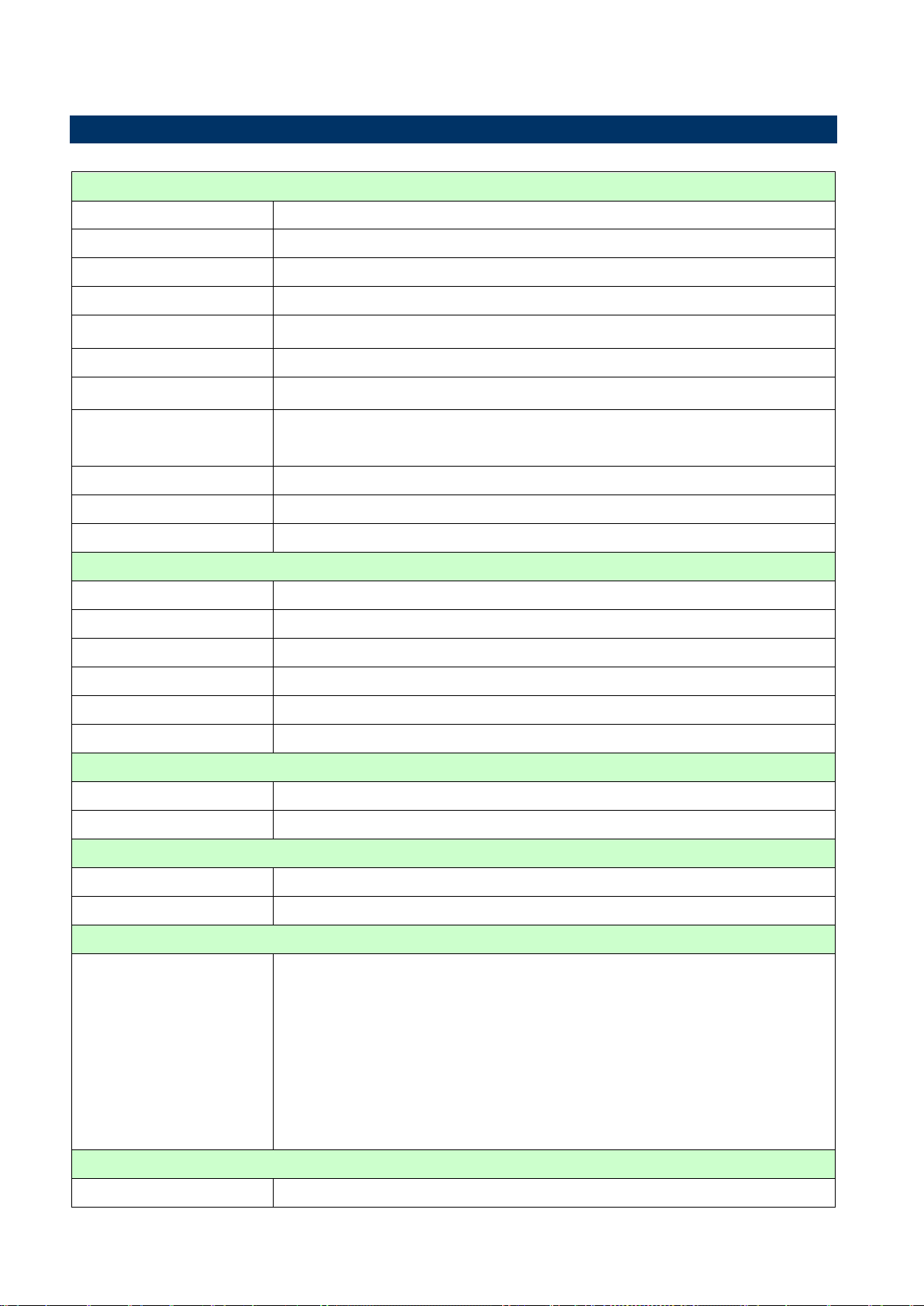
System
CPU
Intel LGA1155 socket supports Intel Core i7/ i5/ i3 CPU
BIOS
AMI 64Mb SPI
System Chipset
Intel® Q77
I/O Chipset
Nuvoton NCT6776F + FINTEK F81216AD
Memory
Four 240-pin UDIMM sockets support up to 32GB dual channel DDR3 1066/ 1333/ 1600
SDRAM
Watchdog Timer
Reset: 1 to 255 sec/min per step
H/W Status Monitor
Monitoring temperature, voltage and cooling fan status. Auto throttling control when CPU
overheats.
Expansion Slots
1 PCI-E x 16 2.0
3 PCI
Power State
S1, S3, S4, S5
Wake up on LAN or Ring
LAN (WOL)
Smart Fan Control
Yes
Display
Chipset
Intel® GMA HD 4000/ 3000 supports DirectX 11, OpenGL 3.1, OpenCL 1.1
Display Memory
Shared Memory up to 512MB
Dual Display
VGA + LVDS, VGA + HDMI, HDMI + LVDS
VGA
Onboard, supports max resolution 2048 x 1536 (@60Hz)
HDMI
Onboard HDMI 1.3, supports max resolution 1920 x 1200 (@60Hz)
LVDS
Onboard, supports max resolution 1920 x 1200 (@60Hz)
Audio
Audio Codec
Realtek ALC892, 5.1 Channel HD Audio
Audio Interface
Line-in, Line-out, Mic-in, S/PDIF, Front Audio Header
Ethernet
LAN1
Intel 82579LM
LAN2
Intel 82574L
Back I/O Port
Back Panel
1 x PS2 KB/MS
1 x VGA
1 x HDMI
2 x COM port
2 x RJ45 port
4 x USB 3.0
1 x 3 Audio Jacks(Line-in/Line-Out/Mic in)
Internal I/O Connector
Internal I/O
4 x SATAII connectors
1.5 System Specifications
12 ERX-Q77 User’s Manual
ERX-Q77 User’s Manual
13
2 x SATAIII connectors
3 x USB connectors support additional 6 USB 2.0 ports
3 x COM header
1 x LVDS connector
1 x CPU Fan connector
1 x System Fan connector
1 x Chassis Intrusion header
1 x Front Audio connector
1 x Front panel header
1 x Printer port
1 x 8 Bit DIO connector
1 x SPDIF header
1 x Amplifier header
1 x 24-pin ATX Power connector
1 x 4-pin ATX 12V Power connector
Mechanical & Environmental
Power Type
AT/ATX
Operating Temperature
0~60°C (32~140°F)
Operating Humidity
0%~90% relative humidity, non-condensing
Size (L x W)
9.6" x 9.6" (243.84 mm x 243.84 mm)
Weight
1.35 lbs = 0.61 Kg
ERX-Q77 User’s Manual
ERX-Q77 User’s Manual
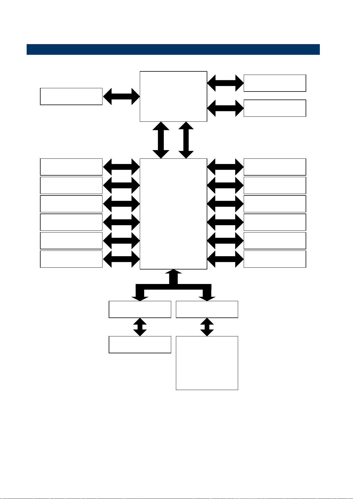
Intel LGA1155
Core i7/ i5/ i3 CPU
Channel A
Channel B
DDR3 1600/
1333/1066MHz
DDR3 1600/
1333/1066MHz
PCI-E x 16
PCI-E x 16 slot
DMI
FDI
Intel Q77
RGB
VGA
DDSP-B
LVDS
DDSP-C
HDMI
HD audio
Realtek ALC892
PCI 33MHz
PCI slot
SPI
SPI ROM
PCIe x1
PCIe x1
USB 2.0
USB 3.0
SATA 3.0
SATA 2.0
LAN1
Intel 82579LM
LAN2
Intel 82574L
USB 2.0 6 ports
USB 3.0 4 ports
SATA 3.0 2 ports
SATA 2.0 4 ports
LPC
Fintek
81216AD
Nuvoton
NCT6776F
3 RS-232 ports
2 RS-232 ports
2 PS2 KB/MS
FAN control
H/W monitor
8-bit GPIO
LPT
1.6 Architecture Overview – Block Diagram
14 ERX-Q77 User’s Manual

ERX-Q77 User’s Manual
15
2. Hardware
Configuration
ERX-Q77 User’s Manual

ERX-Q77 User’s Manual
2.1 Product Overview
Supports latest Intel LGA 1155 CPU-socket interface processor, the 3rd Generation Intel®
Core i3, i5, i7 desktop processors which are built on 22/32 nm technologies to provide smart
performance and responsiveness on executing tasks, It combines the CPU and GPU to offer
fantastic HD media and graphics, especially on 3D gaming experience. Doubles the
bandwidth of your system memory up to 32GB/s and pumps up the system performance at
lower power.
DMI (Direct Media Interface ) architecture connects between the processor and chipset at
5.0GT/s which twice the speed of previous version. The exceptionally increased interconnect
bit rate from 2.5GT/s up to 5.0GT/s would effectively eliminates the bottle neck of the system
performance and brings the most terrific computing experience from the present to the future.
Doubles the transfer speed of SATA 3G, running at speed up to 6.0Gb/s, and can connect
with any other SATA 3.0Gb/s and 1.5Gb/s devices for backward compatibility.
Supports RAID 0(Striped disk array), RAID 1(Mirroring disk array), RAID 5(Block Interleaved
Distributed Parity), RAID 10 (A Stripe of Mirrors). Provides users the performance and
protection. Integrated 5.1-channel HD Audio CODEC delivering advanced multi-channel
audio and bringing you the experience of home theater-quality sound. Delivers transfer speed
ten times faster than conventional 10/ 100 Ethernet connections, supporting a high transfer
rate up to Gigabit/s. Gigabit LAN is the networking standards for the future and is ideal for
handing large amount of data such as video, audio, and voice.
Choose an environment-friendly, fully RoHS-compliant ECS product as the foundation for
keeping harmful substances out of our ecosystem.
2.1.1 Platform Features and Benefits
•Integrated Gfx (Intel® HD Graphics 4000/3000) with enhanced operating modes to enable
excellent graphics performance in power and cost sensitive embedded applications
• DirectX® 11 & Open CL 1.1 let you enjoy awesome graphics performance, stunning 3D
visual effect and dynamic interactivity
• Memory support, integrated low voltage DDR3 memory controller
• Operating system support:
- Window XP 32 bit / 64 bit
- Window Vista 32 bit / 64 bit
- Window 7 32 bit / 64 bit
- Window 8 32 bit / 64 bit
- Fedora Core 17 (32/64bit)
- Ubuntu 12.04 x86 (04.30.2012)
16 ERX-Q77 User’s Manual

ERX-Q77 User’s Manual
17
- POS Ready 2009
- OpenSUSE 12.1 x86
2.1.2 Key Architecture Features
•Supports Intel LGA 1155 CPU, the 3nd Generation Intel® Core i3, i5, i7 desktop processors.
- 22/32nm monolithic die
- Integrated Gfx (Intel® HD Graphics 4000/3000) & memory controller
- 4 &2 Cores, up to 8MB cache
- HW accelerated video CODECs
- Compatible with high speed DDR3-1600
- TDP: 35W-95W
• Intel® Turbo Boost Technology
-More efficient power sharing between CPU and Graphics
• Intel® Hyper-Threading Technology
• Intel® Advanced Vector Extensions (Intel® AVX)
• Intel® AES-New Instructions
• Integrated Display Interfaces
- Dual Independent Display Support
- HDMI
- LVDS
- Analog VGA
• Intel® HD Graphics 4000/3000
- DirectX® 11
- Improved realism for DX 3D applications and rendering.
- OpenCL 1.1
- Improved realism for OGL 3D based application
- UVD (Unified Video Decoder) 2.01
Hardware decode of most common HD codecs (MPEG-2, H.264/AVC MPEG-4 and
VC-1)
- Supports ATI Hybrid CrossFireXTM Technology2
• Intel Quick Sync Video
- Enables faster and higher quality video editing, recording and sharing
• I/O
- PCI Express® x 16 Gen 3 (8GT/s)
- PCI 2.3 interface x 3
- Six SATA ports (2 port of Gen 3.0 and 4 ports of Gen 2.0) support RAID 0,1, 5, 10
- Gigabit Ethernet Media Access Controller (GbE MAC)
IPv4 and IPv6 Checksum Offload
- High Definition Audio
- USB: 3.0, up to 4 ports
ERX-Q77 User’s Manual
ERX-Q77 User’s Manual
Unplug the power cord from the wall socket before touching any
component.
Use a grounded wrist strap or touch a safely grounded object or a
metal object, such as the power supply case, before handling
components to avoid damaging them due to static electricity
Hold components by the edges to avoid touching the ICs on
them.
Whenever you uninstall any component, place it on a grounded
anti-static pad or in the bag that came with the component.
Before you install or remove any component, ensure that the ATX
power supply is switched off or the power cord is detached from
the power supply. Failure to do so may cause severe damage to
the motherboard, peripherals, and/or components.
- USB: 2.0, up to 6 ports
- SMBus 2.0
- LPC Bus
Supports SPI devices
- Hardware Monitor
Fan control (Voltage, Temp)
Watchdog timer
• Power Management
- Support AT/ATX mode
- Advanced Configuration and Power Interface (ACPI) 3.0
2.2 Before you Proceed
Take note of the following precautions before you install motherboard components or change
any motherboard settings.
18 ERX-Q77 User’s Manual
ERX-Q77 User’s Manual
19
Make sure to unplug the power cord before installing or removing the
motherboard. Failure to do so can cause you physical injury and
damage motherboard components.
Place this side towards the rear of
the chassis.
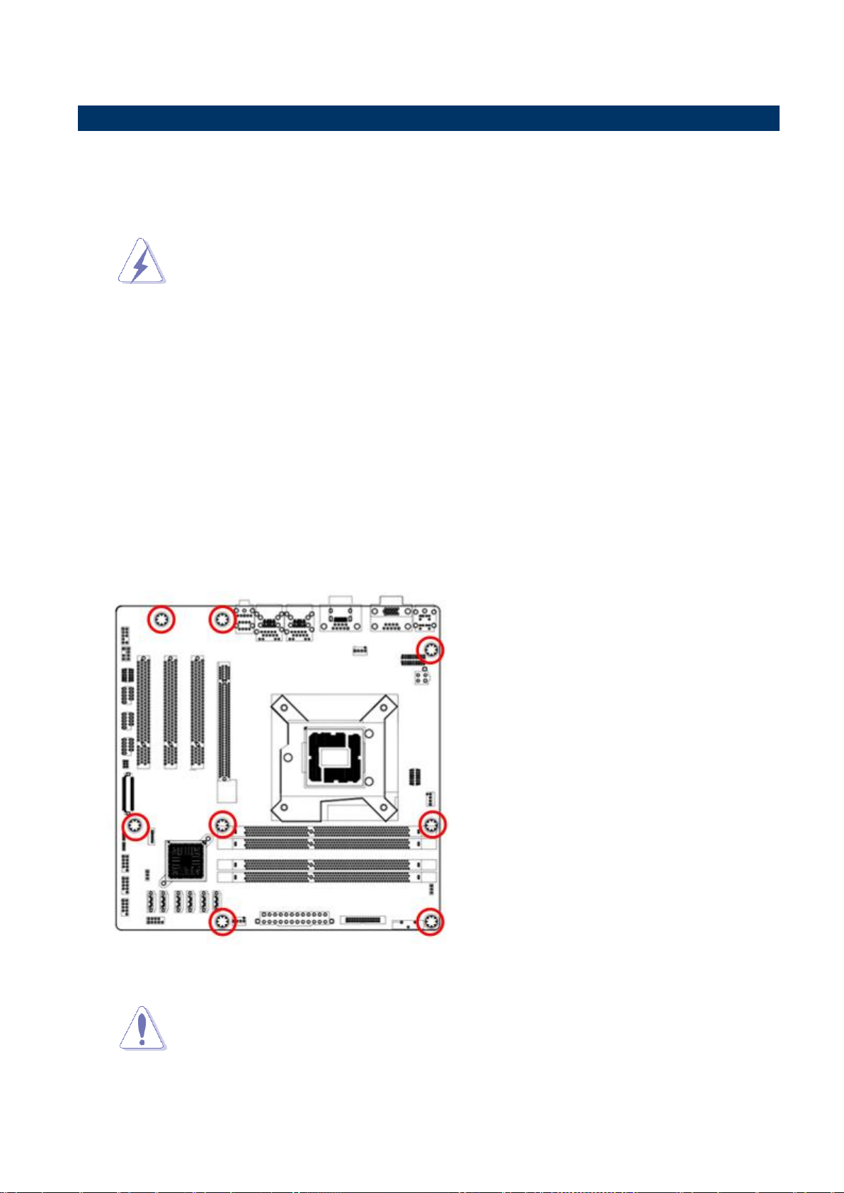
Do not over tighten the screws! Doing so can damage the
motherboard.
2.3 Motherboard Overview
Before you install the motherboard, study the configuration of your chassis to ensure that the
motherboard fits into it. Refer to the chassis documentation before installing the motherboard.
2.3.1 Placement direction
When installing the motherboard, make sure that you place it into the chassis in the correct
orientation. The edge with external ports goes to the rear part of the chassis as indicated in
the image below.
2.3.2 Screw Holes
Place eight (8) screws into the holes indicated by circles to secure the motherboard to the
chassis.
ERX-Q77 User’s Manual
ERX-Q77 User’s Manual
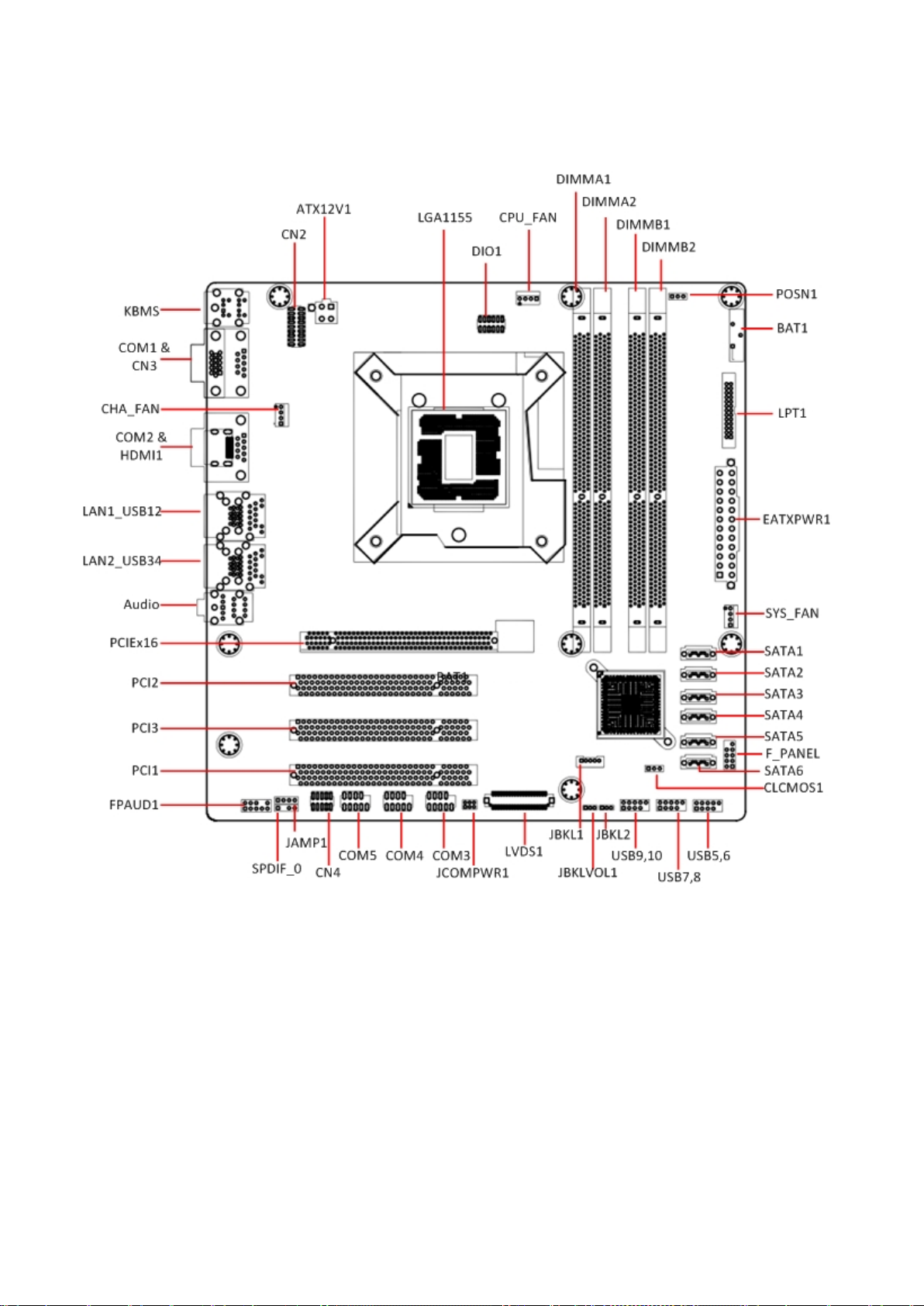
2.3.3 Motherboard Layout
20 ERX-Q77 User’s Manual
21
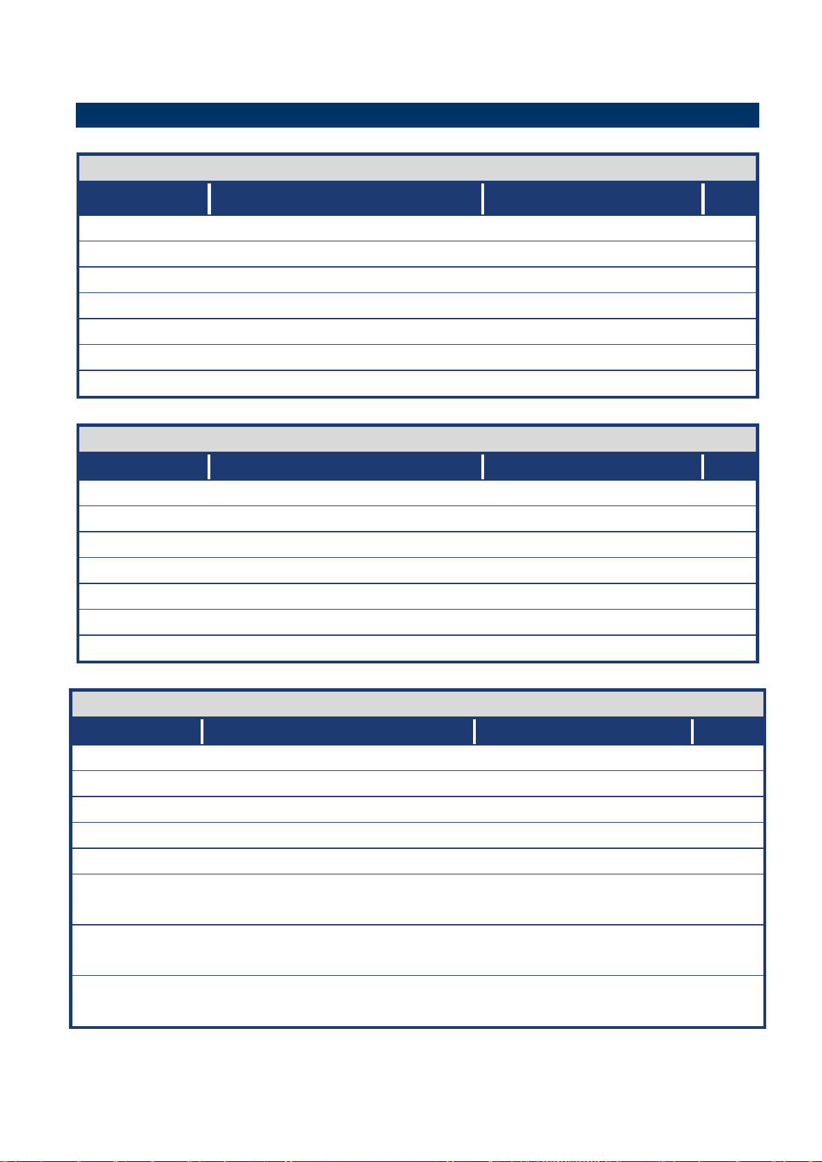
Slots & socket
Label
Function
Note
LGA1155
LGA1155 socket
P23
DIMMA1
240-pin DDR3 DIMM Slot A1
P30
DIMMA2
240-pin DDR3 DIMM Slot A2
P30
DIMMB1
240-pin DDR3 DIMM Slot B1
P30
DIMMB2
240-pin DDR3 DIMM Slot B2
P30
PCIEX16
PCI-e x16 Slot
P36
PCI1~3
PCI Slot
P36
Jumpers
Label
Function
Note
CLCMOS1
Clear CMOS
3 x 1 header, pitch 2.54mm
P37
PSON1
AT/ATX Mode Select
3 x 1 header, pitch 2.54mm
P38
CN2
COM1 RS232/422/485 SETTING
9 x 2 header, pitch 2.00mm
P38
CN4
COM5 RS232/485 SETTING
5 x 2 header, pitch 2.00mm
P39
JCOMPWR1
COM3 POWER SETTING
3 x 2 header, pitch 2.00mm
P39
JBKLVOL1
LVDS Backlight power selection
3 x 1 header, pitch 2.00mm
P40
JBKL2
LVDS Backlight control mode
3 x 1 header, pitch 2.00mm
P40
Rear Panel Connector
Label
Function
Note
KBMS
PS/2 Keyboard and Mouse
6-pin Mini-Din
P41
COM1
COM1 Connector
D-sub 9-pin, male
P41
COM2
COM2 Connector
D-sub 9-pin, male
P41
CN3
VGA Port
D-sub 15-pin, female
P41
HDMI1
HDMI Port
HDMI 1.3 19-pin
P41
LAN1_USB12
RJ-45 Ethernet Connector x 1
USB 3.0 Connector x 2
P41~42
LAN2_USB34
RJ-45 Ethernet Connector x 1
USB 3.0 Connector x 2
P41~42
Audio
Audio Line-In , Line-Out , Mic.-In
5.1 Channel Audio I/O (3
jacks)
P42
2.4 Jumper and Connector List
ERX-Q77 User’s Manual
ERX-Q77 User’s Manual

ERX-Q77 User’s Manual
Internal Connector
Label
Function
Note
CPU_FAN
CPU Fan Connector
4 x 1 wafer, pitch 2.54mm
P43
SYS_FAN
System Fan Connector
4 x 1 wafer, pitch 2.54mm
P43
CHA_FAN
Chassis Fan Connector
4 x 1 wafer, pitch 2.54mm
P43
F_PANEL
Intel Front Panel connector
5 x 2 header, pitch 2.54mm
P44
EATXPWR1
ATX power connectors
12 x 2 wafer
P45
ATX12V1
12V ATX power connectors
2 x 2 wafer
P45
COM3 ~ 5
Serial Port Connector
5 x 2 header, pitch 2.54mm
P46
DIO1
Digital I/O Connector
6 x 2 header, pitch 2.54mm
P46
FPAUD1
Audio Mic.-In & Line-Out Connector
5 x 2 header, pitch 2.54mm
P47
SPDIF_O
Digital Audio connector
4 x 1 header, pitch 2.54mm
P48
JAMP1
Amplifier Connector
4 x 1 header, pitch 2.54mm
P48
SATA1 ~ 6
SATA Data Connector * 6
7P Male connector
P49
USB5~10
USB Connector * 6
5 x 2 header, pitch 2.54mm
P50
LVDS1
LVDS Connector
20 x 2 wafer
P51
JBKL1
LVDS Inverter Power Connector
5 x 1 wafer, pitch 2.00mm
P51
LPT1
Print Port Connector
13 x 2 wafer, pitch 2.00mm
P52
2.4.1 Internal Connectors
22 ERX-Q77 User’s Manual
ERX-Q77 User’s Manual
23
Your boxed Intel® Core™ i7/ i5/ i3 LGA1155 processor package
should come with installation instructions for the CPU, fan and
heatsink assembly. If the instructions in this section do not match
the CPU documentation, follow the latter.
Upon purchase of the motherboard, make sure that the PnP cap
is on the socket and the socket pins are not bent. Contact your
retailer immediately if the PnP cap is missing, or if you see any
damage to the PnP cap/socket pins/motherboard components.
ADVANSUS will shoulder the cost of repair only if the damage is
shipment/transit-related.
Keep the cap after installing the motherboard. ADVANSUS will
process Return Merchandise Authorization (RMA) requests only
if the motherboard comes with the cap on the LGA1155 socket.
The product warranty does not cover damage to the socket pins
resulting from incorrect CPU installation/removal, or
misplacement/loss/incorrect removal of the PnP cap.
Install the CPU fan and heatsink assembly before you install
motherboard to the chassis.
If you purchased a separate CPU heatsink and fan assembly, make
sure that you have properly applied Thermal Interface Material to the
CPU heatsink or CPU before you install the heatsink and fan
assembly.
2.5 Central Processing Unit (CPU)
The motherboard comes with a surface mount LGA1155 socket designed for the Intel®
Core™ i7/ i5/ i3 processor in the 1155-land package.
ERX-Q77 User’s Manual

ERX-Q77 User’s Manual
Before installing the CPU, make sure that the socket box is facing
towards you and the load lever is on your left.
To prevent damage to the socket pins, do not remove the PnP cap
unless you are installing a CPU.
A B Retention tab
Load lever
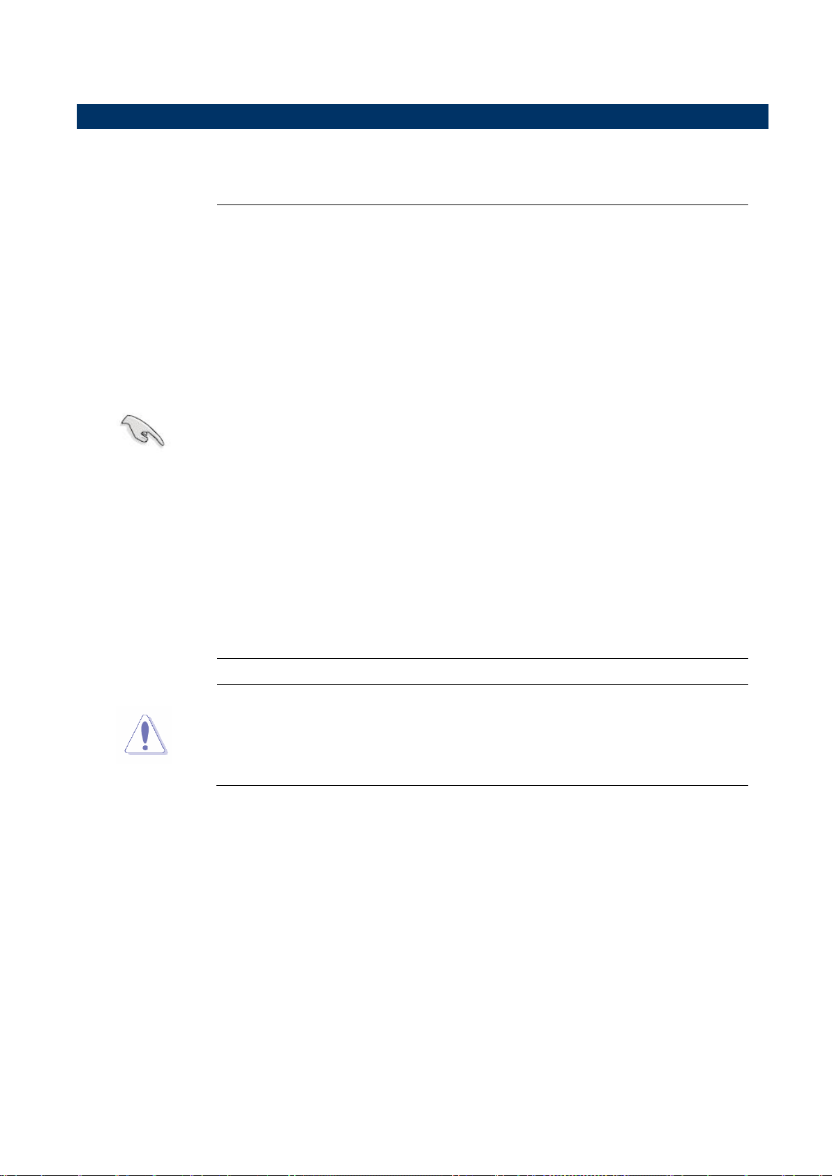
2.5.1 Installing the CPU
1 Locate the CPU socket on the motherboard.
2 Press the load lever with your thumb (A), then move it to the left (B) until it is released
from the retention tab.
24 ERX-Q77 User’s Manual
ERX-Q77 User’s Manual
25
5. Pull back the load lever , then push the load
lever (A) until it snaps into the retention tab.
The CPU fits in only one correct orientation. DO NOT force the CPU
into the socket to prevent bending the connectors on the socket and
damaging the CPU!
Alignment key
CPU notch
Gold triangle
B
A
A
3. Lift the Load lever with your thumb and forefinger to around 180º angle (A), then pull the
PnP cap from the CPU socket to remove (B).
4. Position the CPU over the socket, making sure that the gold triangle is on the top-left
corner of the socket then fit the socket alignment key into the CPU notch.
ERX-Q77 User’s Manual
ERX-Q77 User’s Manual
Install the motherboard to the chassis before you install the CPU
fan and heatsink assembly.
When you buy a boxed Intel® Core™ i7/ i5/ i3 LGA1155
processor, the package includes the CPU fan and heatsink
assembly. If you buy a CPU separately, make sure that you use
only Intel® certified multi‑directional heatsink and fan.
Your Intel® Core™ i7/ i5/ i3 LGA1155 processor LGA1155
heatsink and fan assembly comes in a push-pin design and
requires no tool to install.
If you purchased a separate CPU heatsink and fan assembly, make
sure that you have properly applied Thermal Interface Material to the
CPU heatsink or CPU before you install the heatsink and fan
assembly.
Orient the heatsink and fan assembly such that the CPU fan cable is
closest to the CPU fan connector.
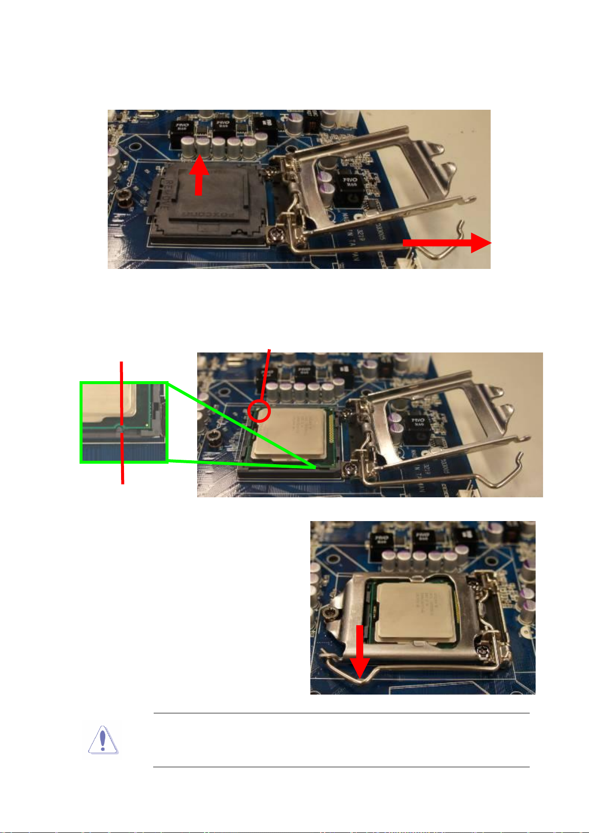
Make sure each fastener is oriented as shown, with the narrow
groove directed outward.
Motherboard hole
Fastener
Narrow end of
the groove
2.5.2 Installing the CPU Heatsink and Fan
Intel® Core™ i7/ i5/ i3 LGA1155 processor requires a specially designed heatsink and fan
assembly to ensure optimum thermal condition and performance.
1. Place the heatsink on top of the installed CPU, making sure that the four fasteners match
the holes on the motherboard.
26 ERX-Q77 User’s Manual

ERX-Q77 User’s Manual
27
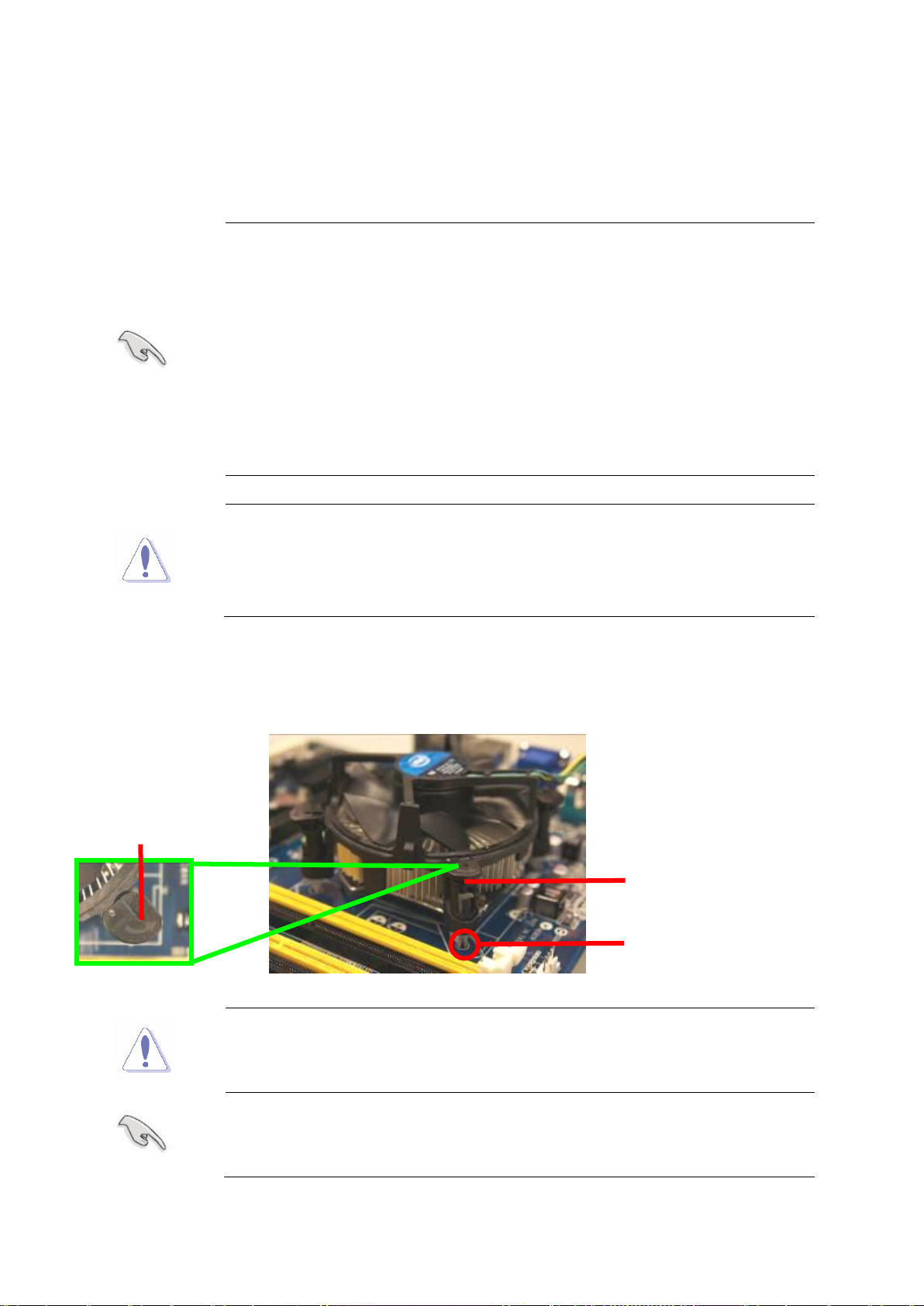
2. Push down two fasteners at a time in a
diagonal sequence to secure the heatsink and fan
assembly in place.
FAN 1
CPU FAN
Do not forget to connect the fan cables to the fan
connectors. Insufficient air flow inside the system may
damage the motherboard components.
These are not jumpers! DO NOT place jumper caps on the
fan connectors.
A A B
B
A
B
A
B
3. Connect the CPU fan cable to the connector on the motherboard labeled CPU_FAN.
ERX-Q77 User’s Manual
ERX-Q77 User’s Manual
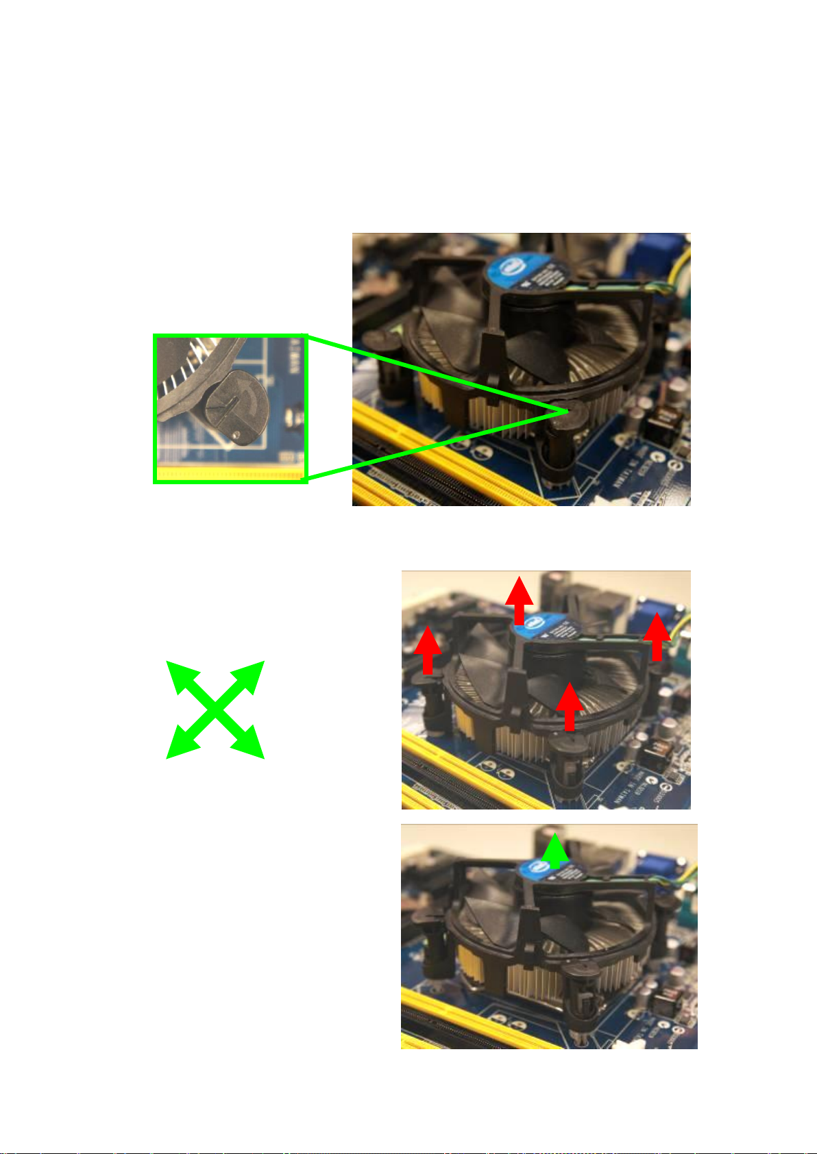
4. Carefully remove the heatsink and fan
assembly from the motherboard.
A B A
B
A A B
B
2.5.3 Uninstalling the CPU Heatsink and Fan
To uninstall the CPU heatsink and fan:
1. Disconnect the CPU fan cable from the connector on the motherboard.
2. Rotate each fastener counterclockwise
3. Pull up two fasteners at a time in a diagonal sequence to disengage the heatsink and fan
assembly from the motherboard.
28 ERX-Q77 User’s Manual