

EQM-CDV
Intel Cedarview Qseven Module
Quick Installation Guide
1st Ed – 20 February 2012
Notice
This guide is designed for experienced users to setup the system within the
shortest time. For detailed information, please always refer to the electronic
user's manual.
Copyright Notice
Copyright 2012 Avalue Technology Inc., ALL RIGHTS RESERVED.
Part No.E2017221100R

EQM-CDV
Content
1. Getting Started ........................................................................................................... 3
1.1 Safety Precautions ................................................................................................ 3
2. Hardware Configuration ............................................................................................ 4
2.1 Product Overview .................................................................................................. 5
2.2 Jumper and Connector List.................................................................................... 6
2.3 Setting Jumpers & Connectors .............................................................................. 7
2.3.1 QSeven connector (GF1) ................................................................................. 7
2 EQM-CDV Quick Installation Guide
Quick Installation Guide
1. Getting Started
1.1 Safety Precautions
Warning!
Always completely disconnect the power cord from your
chassis whenever you work with the hardware. Do not
make connections while the power is on. Sensitive
electronic components can be damaged by sudden power
surges. Only experienced electronics personnel should
open the PC chassis.
Caution!
Always ground yourself to remove any static charge before
touching the CPU card. Modern electronic devices are very
sensitive to static electric charges. As a safety precaution,
use a grounding wrist strap at all times. Place all electronic
components in a static-dissipative surface or static-shielded
bag when they are not in the chassis.
EQM-CDV Quick Installation Guide 3

EQM-CDV
2. Hardware
Configuration
4 EQM-CDV Quick Installation Guide
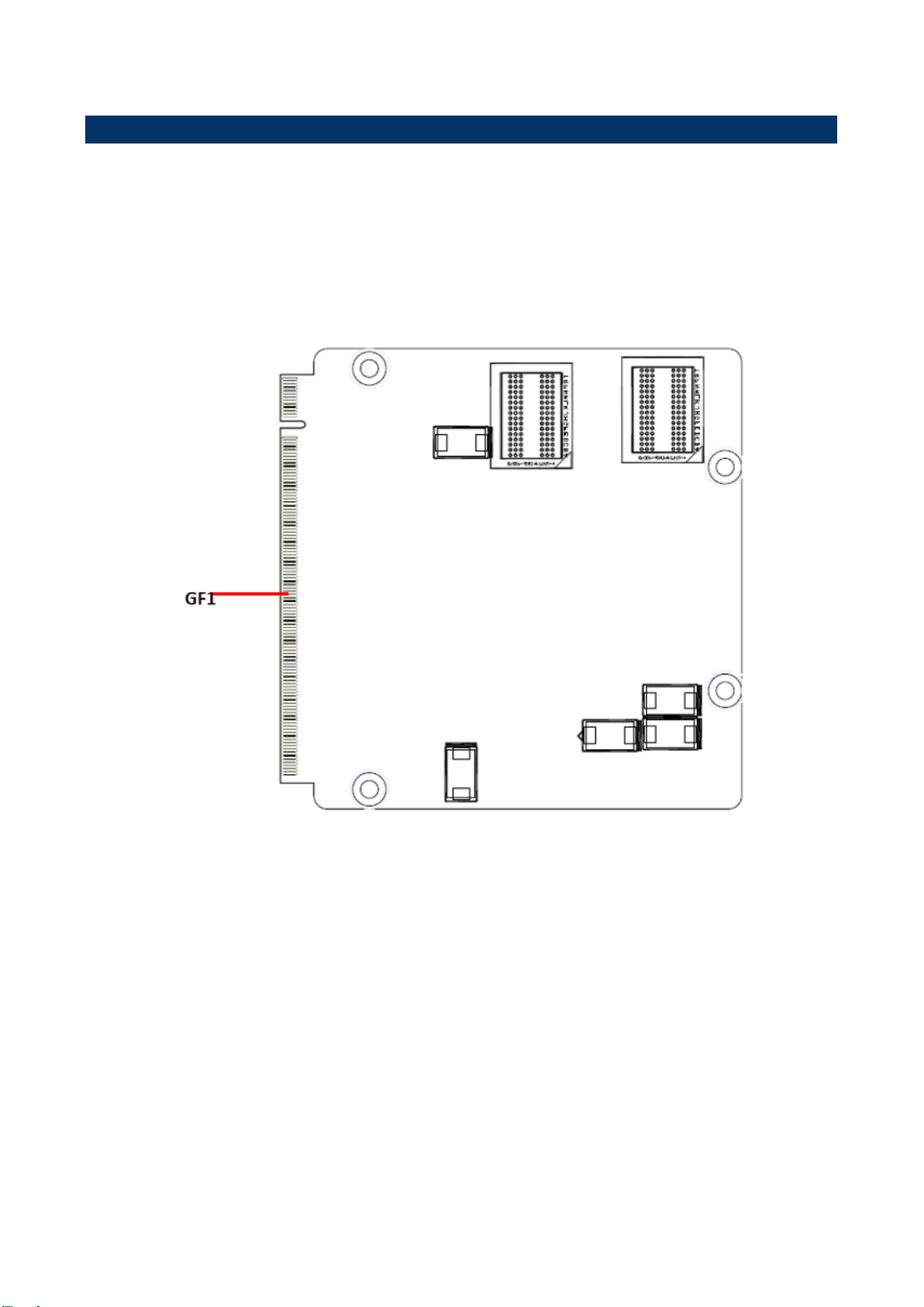
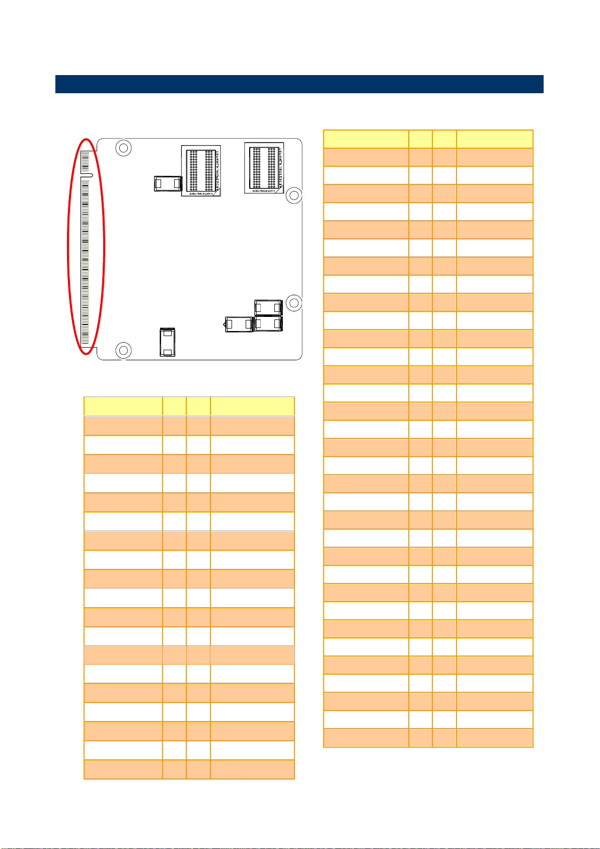
2.1 Product Overview
Quick Installation Guide
EQM-CDV Quick Installation Guide 5
EQM-CDV
Connectors
Label
Function
Note
GF1
QSeven connector
2.2 Jumper and Connector List
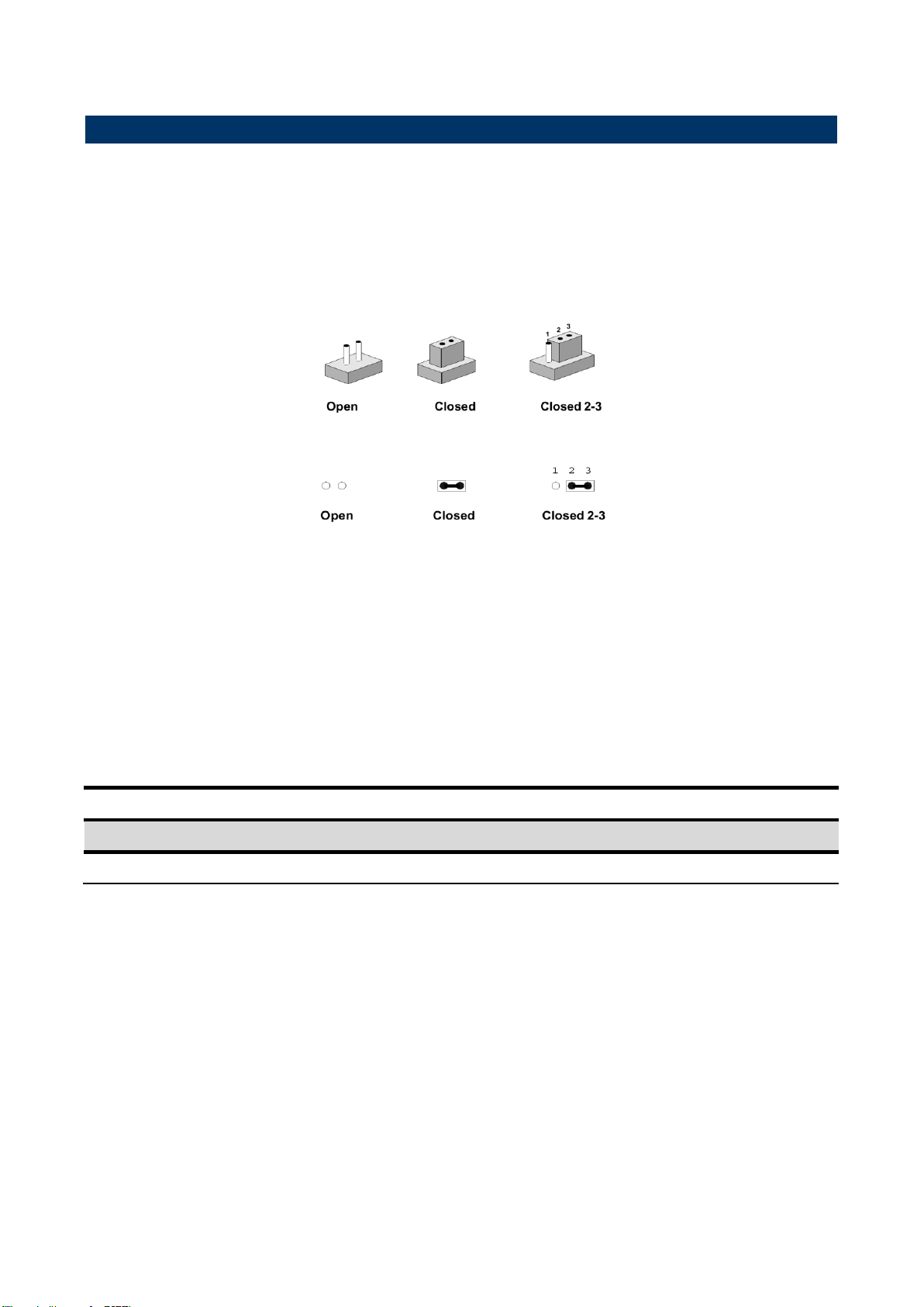
You can configure your board to match the needs of your application by setting jumpers. A
jumper is the simplest kind of electric switch.
It consists of two metal pins and a small metal clip (often protected by a plastic cover) that
slides over the pins to connect them. To “close” a jumper you connect the pins with the clip.
To “open” a jumper you remove the clip. Sometimes a jumper will have three pins, labeled 1,
2, and 3. In this case, you would connect either two pins.
The jumper settings are schematically depicted in this manual as follows:
A pair of needle-nose pliers may be helpful when working with jumpers.
Connectors on the board are linked to external devices such as hard disk drives, a
keyboard, or floppy drives. In addition, the board has a number of jumpers that allow you to
configure your system to suit your application.
If you have any doubts about the best hardware configuration for your application, contact
your local distributor or sales representative before you make any changes.
The following tables list the function of each of the board's jumpers and connectors.
6 EQM-CDV Quick Installation Guide
Quick Installation Guide
*Default
Signal
PIN
PIN
Signal
GND7
39
40
GND8
BIOS_DISABLE#
41
42
NC
NC
43
44
NC
NC
45
46
NC
NC
47
48
NC
NC
49
50
NC
NC
51
52
NC
NC
53
54
NC
NC
55
56
NC
GND9
57
58
GND10
HDA_SYNC
59
60
SMB_CLK
HDA_RST#
61
62
SMB_DAT
HDA_BCLK
63
64
SMB_ALERT#
HDA_SDI
65
66
NC
HDA_SDO
67
68
NC
THRM#
69
70
NC
NC
71
72
NC
GND11
73
74
GND12
USB_P7-
75
76
USB_P6
USB_P7+
77
78
USB_P6
USB_6_7_OC#
79
80
USB_4_5_OC#
USB_P5-
81
82
USB_P4-
USB_P5+
83
84
USB_P4+
USB_2_3_OC#
85
86
USB_0_1_OC#
USB_P3-
87
88
USB_P2-
USB_P3+
89
90
USB_P2+
NC
91
92
NC
USB_P1-
93
94
USB_P0-
USB_P1+
95
96
USB_P0+
GND13
97
98
GND14
LVDS_A0+
99
100
NC
LVDS_A0-
101
102
NC
LVDS_A1+
103
104
NC
Signal
PIN
PIN
Signal
GND1
1 2 GND2
GBE_MDI3-
3 4 GBE_MDI2-
GBE_MDI3+
5 6 GBE_MDI2+
GBE_LINK100#
7 8 GBE_LINK1000#
GBE_MDI1-
9
10
GBE_MDI0-
GBE_MDI1+
11
12
GBE_MDI0+
NC
13
14
GBE_ACT#
GBE_CTREF
15
16
SUS_S5#
WAKE#
17
18
SUS_S3#
SUS_STAT#
19
20
PWRBTN#
SLP_BTN#
21
22
LID_BTN#
GND3
23
24
GND4
GND5
25
26
PWGIN
BATLOW#
27
28
RSTBTN#
SATA0_TX+
29
30
SATA1_TX+
SATA0_TX-
31
32
SATA1_TX-
SATA_ACT#
33
34
GND6
SATA0_RX+
35
36
SATA1_RX+
SATA0_RX-
37
38
SATA1_RX-
2.3 Setting Jumpers & Connectors
2.3.1 QSeven connector (GF1)
EQM-CDV Quick Installation Guide 7

EQM-CDV
Signal
PIN
PIN
Signal
LVDS_A1-
105
106
NC
LVDS_A2+
107
108
NC
LVDS_A2-
109
110
NC
LVDS_PPEN
111
112
LVDS_BLEN
LVDS_A3+
113
114
NC
LVDS_A3-
115
116
NC
GND15
117
118
GND16
LVDS_A_CLK+
119
120
NC
LVDS_A_CLK-
121
122
NC
LVDS_BLT_CTRL
123
124
NC
LVDS_DID_DAT
125
126
LVDS_BLC_DAT
LVDS_DID_CLK
127
128
LVDS_BLC_CLK
NC
129
130
NC
SDVO_BCLK+
131
132
NC
SDVO_BCLK-
133
134
NC
GND17
135
136
GND18
SDVO_GREEN+
137
138
NC
SDVO_GREEN-
139
140
NC
GND19
141
142
GND20
SDVO_BLUE+
143
144
NC
SDVO_BLUE-
145
146
NC
GND21
147
148
GND22
SDVO_RED+
149
150
SDVO_CTRL_DAT
SDVO_RED-
151
152
SDVO_CTRL_CLK
HDMI_HPD#
153
154
NC
PCIE_CLK_REF+
155
156
PCIE_WAKE#
PCIE_CLK_REF-
157
158
PCIE_RST#
GND23
159
160
GND24
NC
161
162
NC
NC
163
164
NC
GND25
165
166
GND26
PCIE2_TX+
167
168
PCIE2_RX+
PCIE2_TX-
169
170
PCIE2_RX-
Signal
PIN
PIN
Signal
EXCD0_PERST#
171
172
EXCD1_PERST#
PCIE1_TX+
173
174
PCIE1_RX+
PCIE1_TX-
175
176
PCIE1_RX-
NC
177
178
NC
PCIE0_TX+
179
180
PCIE0_RX+
PCIE0_TX-
181
182
PCIE0_RX-
GND27
183
184
GND28
LPC_AD0
185
186
LPC_AD1
LPC_AD2
187
188
LPC_AD3
LPC_CLK
189
190
LPC_FRAME#
SERIRQ
191
192
LPC_LDRQ#
VCC_RTC
193
194
SPKR
FAN_TACHOIN
195
196
FAN_PWMOUT
GND29
197
198
GND30
RSVD199
199
200
RSVD200
RSVD201
201
202
NC
RSVD203
203
204
NC
VCC_5V_SB1
205
206
VCC_5V_SB2
NC
207
208
NC
NC
209
210
NC
VCC1
211
212
VCC2
VCC3
213
214
VCC4
VCC5
215
216
VCC6
VCC7
217
218
VCC8
VCC9
219
220
VCC10
VCC11
221
222
VCC12
VCC13
223
224
VCC14
VCC15
225
226
VCC16
VCC17
227
228
VCC18
VCC19
229
230
VCC20
8 EQM-CDV Quick Installation Guide
 Loading...