


EPI-LX800 Series
AMD Geode GX3 EPIC Module
Quick Installation Guide
1st Ed – 08 August 2006
To receive the latest version of the user’s manual; please visit our Web site
at:
http://www.avalue.com.tw
Copyright Notice
Copyright © 2007 Avalue Technology Inc., ALL RIGHTS RESERVED.
Part No. E2017352500R

EPI-LX800 Series
Contents
1. Getting Started............................................................................................................3
1.1 Safety Precautions ................................................................................................3
1.2 Packing List ...........................................................................................................3
2. Hardware Configuration.............................................................................................4
2.1 Product Overview ..................................................................................................5
2.2 Jumper and Connector List ...................................................................................6
2.3 Setting Jumpers & Connectors..............................................................................8
2.3.1 Clear CMOS (JBAT) .................................................................................................................... 8
2.3.2 PCI-104 Voltage Select (JP2)...................................................................................................... 8
2.3.3 COM1 Pin 9 Signal Select (JP3)..................................................................................................9
2.3.4 CF Master/Slave Mode Select (JP5) ........................................................................................... 9
2.3.5 Speaker/Headphone Audio Output Select (JP6) ....................................................................... 10
2.3.6 4/5/8-wire Touch Screen Select (SW1) (Optional) .................................................................... 10
2.3.7 CPU/Memory Select (SW2) (Bit 1~5) ........................................................................................ 11
2.3.8 AT/ATX Power Select (SW2) (Bit 6) .......................................................................................... 12
2.3.9 4/5/8-Wire Touch Screen Connector (CN4) (Optional).............................................................. 12
2.3.10 Serial Port 1 Connector in RS-232 Mode (COM1) ................................................................ 13
2.3.11 Serial Port 1 Connector in RS-422 Mode (COM1) ................................................................ 13
2.3.12 Serial Port 1 Connector in RS-485 Mode (COM1) ................................................................ 14
2.3.13 Serial Port 2 Connector (COM2) ........................................................................................... 14
2.3.14 LCD Inverter Connector (JBKL)............................................................................................. 15
2.3.15 CD-ROM Audio Input Connector (JCD) ................................................................................ 15
2.3.16 General Purpose Input/Output Connector (JDIO) ................................................................. 16
2.3.17 IrDA Connector (JIR) ............................................................................................................. 16
2.3.18 LVDS Connector (JLVDS) ..................................................................................................... 17
2.3.19 SW Suspend Connector (JP7) .............................................................................................. 18
2.3.20 ATX Power Switch Connector (JP8)...................................................................................... 18
2.3.21 TFT Panel Connector (JTFT) ................................................................................................ 19
2.3.22 LCD Backlight Brightness Adjustment Connector (JVR)....................................................... 20
2 EPI-LX800 Series Quick Installation Guide
Quick Installation Guide
1. Getting Started
1.1 Safety Precautions
Warning!
Always completely disconnect the power cord from your
chassis whenever you work with the hardware. Do not
make connections while the power is on. Sensitive
electronic components can be damaged by sudden power
surges. Only experienced electronics personnel should
open the PC chassis.
Caution!
Always ground yourself to remove any static charge before
touching the CPU card. Modern electronic devices are very
sensitive to static electric charges. As a safety precaution,
use a grounding wrist strap at all times. Place all electronic
components in a static-dissipative surface or static-shielded
bag when they are not in the chassis.
1.2 Packing List
Before you begin installing your single board, please make sure that the
following materials have been shipped:
z 1 x EPI-LX800 AMD Geode GX3 EPIC Module
z 1 x Quick Installation Guide for EPI-LX800
z 1 x CD-ROM or DVD-ROM contains the followings:
— User’s Manual (this manual in PDF file)
— Ethernet driver and utilities
— VGA drivers and utilities
— Audio drivers and utilities
z 1 x Cable set contains the followings:
— 1 x IDE HDD cable (44-pin, pitch 2.0mm)
— 1 x PS/2 Keyboard & mouse Y cable (6-pin, Mini-DIN
EPI-LX800 Series Quick Installation Guide 3

EPI-LX800 Series
2. Hardware
Configuration
4 EPI-LX800 Series Quick Installation Guide
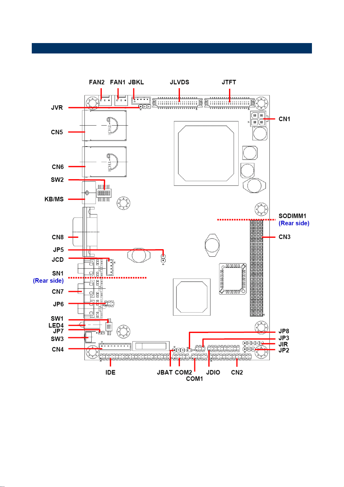
2.1 Product Overview
Quick Installation Guide
EPI-LX800 Series Quick Installation Guide 5
EPI-LX800 Series
2.2 Jumper and Connector List
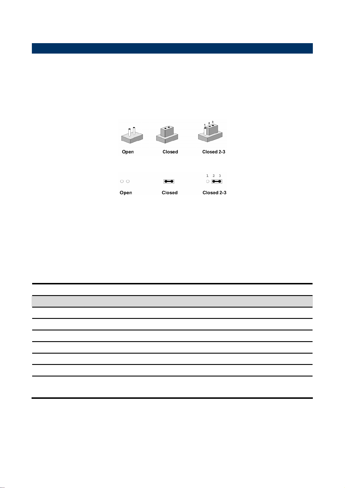
You can configure your board to match the needs of your application by setting jumpers. A
jumper is the simplest kind of electric switch.
It consists of two metal pins and a small metal clip (often protected by a plastic cover) that
slides over the pins to connect them. To “close” a jumper you connect the pins with the clip.
To “open” a jumper you remove the clip. Sometimes a jumper will have three pins, labeled 1,
2, and 3. In this case, you would connect either two pins.
The jumper settings are schematically depicted in this manual as follows:
A pair of needle-nose pliers may be helpful when working with jumpers.
Connectors on the board are linked to external devices such as hard disk drives, a
keyboard, or floppy drives. In addition, the board has a number of jumpers that allow you to
configure your system to suit your application.
If you have any doubts about the best hardware configuration for your application, contact
your local distributor or sales representative before you make any changes.
The following tables list the function of each of the board's jumpers and connectors.
Jumpers
Label Function Note
JBAT
JP2
JP3
JP5
JP6
SW1
Clear CMOS 3 x 1 header, pitch 2.54mm
PCI-104 voltage select 3 x 1 header, pitch 2.54mm
COM1 pin 9 signal select 3 x 2 header, pitch 2.0mm
CF master/slave mode select 2 x 1 header, pitch 2.54mm
Speaker/Headphone audio output select 3 x 2 header, pitch 2.54mm
4/5/8-wire touch screen select (Optional) Switch
SW2
6 EPI-LX800 Series Quick Installation Guide
AT/ATX power & CPU/Memory frequency
select
Switch

Quick Installation Guide
Connectors
Label Function Note
CN1
CN2
CN3
CN4
CN5
CN6
CN7
CN8
COM1
COM2
FAN1
FAN2
IDE
JBKL
ATX power connector
Parallel port connector 13 x 2 header, pitch 2.0mm
PCI-104 connector
4/5/8-wire touch screen connector
(Optional)
RJ-45 Ethernet / USB 2 & 3 connector
RJ-45 Ethernet / USB 0 & 1 connector
Audio connector
VGA connector
Serial port 1 connector
Serial port 2 connector 5 x 2 header, pitch 2.0mm
System fan connector 3 x 1 header, pitch 2.54mm
CPU fan connector 3 x 1 header, pitch 2.54mm
Primary IDE connector 22 x 2 header, pitch 2.0mm
LCD inverter connector 5 x 1 header, pitch 2.0mm
9 x 1 wafer, pitch 2.0mm
Phone jack x 3
D-sub 15-pin, female
5 x 2 header, pitch 2.0mm
JCD
JDIO
JIR
JLVDS
JP7
JP8
JTFT
JVR
KB/MS
LED4
SN1
SODIMM1
SW3
CD-ROM audio input connector 4 x 1 wafer, pitch 2.0mm
General purpose I/O connector 10 x 2 header, pitch 2.0mm
IrDA connector 5 x 1 header, pitch 2.54mm
LVDS connector HIROSE DF13-40DP-1.25V
SW suspend connector 2 x 1 header, pitch 2.0mm
Power button connector 2 x 1 header, pitch 2.0mm
TFT panel connector HIROSE DF13-40DP-1.25V
LCD backlight adjustment connector 3 x 1 header, pitch 2.54mm
PS/2 keyboard & mouse connector 6-pin Mini-DIN
Power & HDD indicator
CompactFlash card connector
200-pin DDR SODIMM socket
Reset button
Button
EPI-LX800 Series Quick Installation Guide 7

EPI-LX800 Series
2.3 Setting Jumpers & Connectors
2.3.1 Clear CMOS (JBAT)
* Default
Protect*
Clear CMOS
2.3.2 PCI-104 Voltage Select (JP2)
* Default
+5V*
+3.3V
8 EPI-LX800 Series Quick Installation Guide

2.3.3 COM1 Pin 9 Signal Select (JP3)
* Default
Ring*
Quick Installation Guide
+5V
+12V
2.3.4 CF Master/Slave Mode Select (JP5)
* Default
Master
Slave*
EPI-LX800 Series Quick Installation Guide 9

EPI-LX800 Series
2.3.5 Speaker/Headphone Audio Output Select (JP6)
Speaker*
Headphone
* Default
2.3.6 4/5/8-wire Touch Screen Select (SW1) (Optional)
Wire BIT1 BIT2
* 4, 8 OFF ON
5 ON OFF
* Default
10 EPI-LX800 Series Quick Installation Guide

2.3.7 CPU/Memory Select (SW2) (Bit 1~5)
* Default
Quick Installation Guide
LX700
(CPU @ 433 MHz)
*266 MHz Memory
333 MHz Memory
400 MHz Memory
LX800
(CPU @ 500 MHz)
*266 MHz Memory
333 MHz Memory
400 MHz Memory
EPI-LX800 Series Quick Installation Guide 11

EPI-LX800 Series
2.3.8 AT/ATX Power Select (SW2) (Bit 6)
* Default
AT*
ATX
2.3.9 4/5/8-Wire Touch Screen Connector (CN4) (Optional)
PIN 4-Wire 5-Wire 8-Wire
1 NA NA Right Sense
2 NA NA Left Sense
3 NA NA Bottom Sense
4 NA Sense Top Sense
5 Right LR Right Excite
6 Left LL Left Excite
7 Bottom UR Bottom Excite
8 Top UL Top Excite
9 GND GND GND
12 EPI-LX800 Series Quick Installation Guide

2.3.10 Serial Port 1 Connector in RS-232 Mode (COM1)
Signal PIN PIN Signal
DCD 1 2 RxD
TxD 3 4 DTR
GND 5 6 DSR
RTS 7 8 CTS
Quick Installation Guide
RI/+5V/+12V 9 10 NC
2.3.11 Serial Port 1 Connector in RS-422 Mode (COM1)
Signal PIN PIN Signal
DATA- 1 2 NC
DATA+ 3 4 NC
GND 5 6 NC
NC 7 8 NC
NC 9 10 NC
EPI-LX800 Series Quick Installation Guide 13

EPI-LX800 Series
2.3.12 Serial Port 1 Connector in RS-485 Mode (COM1)
Signal PIN PIN Signal
DATA- 1 2 NC
DATA+ 3 4 NC
GND 5 6 NC
NC 7 8 NC
2.3.13 Serial Port 2 Connector (COM2)
NC 9 10 NC
Signal PIN PIN Signal
DCD 1 2 RxD
TxD 3 4 DTR
GND 5 6 DSR
RTS 7 8 CTS
14 EPI-LX800 Series Quick Installation Guide
RI 9 10 NC

2.3.14 LCD Inverter Connector (JBKL)
Quick Installation Guide
Signal PIN
+12V 1
GND 2
ENBKL 3
VR 4
+5V 5
Note:
For inverters with adjustable Backlight function, it is possible to control the
LCD brightness through the VR signal controlled by JVR. Please see the
JVR section for detailed circuitry information.
2.3.14.1 Signal Description – LCD Inverter Connector (JBKL)
Signal Signal Description
VR Vadj = 0.75V ~ 4.25V (Recommended: 4.7KΩ, >1/16W)
ENBKL LCD backlight ON/OFF control signal
2.3.15 CD-ROM Audio Input Connector (JCD)
Signal PIN
NC 1
CD_L 2
GND 3
CD_R 4
EPI-LX800 Series Quick Installation Guide 15

EPI-LX800 Series
2.3.16 General Purpose Input/Output Connector (JDIO)
Signal PIN PIN Signal
GPO20 1 2 GPI10
GPO21 3 4 GPI11
GPO22 5 6 GPI12
GPO23 7 8 GPI13
GPO30 9 10 GPI14
GPO31 11 12 GPI15
GPO32 13 14 GPI16
GPO33 15 16 GPI17
SMB_CLK 17 18 SMB_DATA
2.3.17 IrDA Connector (JIR)
GND 19 20 +5V
Signal PIN
+5V 1
NC 2
IRRX 3
GND 4
IRTX 5
16 EPI-LX800 Series Quick Installation Guide

2.3.18 LVDS Connector (JLVDS)
Quick Installation Guide
Signal PIN PIN Signal
+5V 2 1 +3.3V
+5V 4 3 +3.3V
I2C_DAT 6 5 I2C_CLK
GND 8 7 GND
Txout0 10 9 Txout1
Txout0# 12 11 Txout1#
GND 14 13 GND
Txout2 16 15 Txout3
Txout2# 18 17 Txout3#
GND 20 19 GND
NC 22 21 NC
NC 24 23 NC
GND 26 25 GND
NC 28 27 NC
NC 30 29 NC
GND 32 31 GND
Txclk 34 33 NC
Txclk# 36 35 NC
GND 38 37 GND
+12V 40 39 +12V
2.3.18.1 Signal Description – LVDS Connector (JLVDS)
Signal Description
I2C interface for panel parameter EEPROM. This EERPOM is mounted on the
I2C_DAT, I2C_CLK
LVDS receiver. The data in the EEPROM allows the EXT module to automatically
set the proper timing parameters for a specific LCD panel.
EPI-LX800 Series Quick Installation Guide 17

EPI-LX800 Series
2.3.19 SW Suspend Connector (JP7)
Signal PIN
EXTSMI# 1
GND 2
2.3.20 ATX Power Switch Connector (JP8)
Signal PIN
PW_BN 1
GND 2
18 EPI-LX800 Series Quick Installation Guide

2.3.21 TFT Panel Connector (JTFT)
Quick Installation Guide
Signal PIN PIN Signal
+5V 2 1 +5V
GND 4 3 GND
+3.3V 6 5 +3.3V
GND 8 7 NC
P1 10 9 P0
P3 12 11 P2
P5 14 13 P4
P7 16 15 P6
P9 18 17 P8
P11 20 19 P10
P13 22 21 P12
P15 24 23 P14
P17 26 25 P16
P19 28 27 P18
P21 30 29 P20
P23 32 31 P22
GND 34 33 GND
FLM 36 35 SHFCLK
LP 38 37 M
NC 40 39 ENBKL
2.3.21.1 Signal Description – TFT Panel Connector (JTFT)
Signal Description
P [0:23] Flat panel data output for 18/24 bit TFT flat panels. Refer to table below for
configurations for various panel types. The flat panel data and control outputs are
all on-board controlled for secure power-on/off sequencing
SHFCLK Shift Clock. Pixel clock for flat panel data
LP Flat panel equivalent of HSYNC (horizontal synchronization)
FLM Flat panel equivalent of VSYNC (vertical synchronization)
M Multipurpose signal, function depends on panel type. May be used as AC drive
control signal or as BLANK# or Display Enable signal
ENBKL Enable backlight signal. This signal is controlled as a part of the panel power
sequencing
EPI-LX800 Series Quick Installation Guide 19

EPI-LX800 Series
2.3.21.2 Signal Description – TFT Panel Display (JTFT)
Signal 18-bit TFT 24-bit TFT
P0 - B0
P1 - B1
P2 B0 B2
P3 B1 B3
P4 B2 B4
P5 B3 B5
P6 B4 B6
P7 B5 B7
P8 - G0
P9 - G1
P10 G0 G2
P11 G1 G3
P12 G2 G4
P13 G3 G5
P14 G4 G6
P15 G5 G7
P16 - R0
P17 - R1
P18 R0 R2
P19 R1 R3
P20 R2 R4
P21 R3 R5
P22 R4 R6
P23 R5 R7
2.3.22 LCD Backlight Brightness Adjustment Connector (JVR)
Signal PIN
+5V
VR
GND
JVR
1
2
3
Variation Resistor
(Recommended: 4.7KΩ, >1/16W)
1
2
3
VCC
JBKL
pin 4
20 EPI-LX800 Series Quick Installation Guide
 Loading...