

Page 1

EPC-CDV
Fanless Intel® Atom™ D2550 Tiny Box PC
with Intel® NM10 Express Chipset
Quick Reference Guide
1st Ed – 27 July 2012
Copyright Notice
Copyright 2012 Avalue Technology Inc., ALL RIGHTS RESERVED.
Part No. E2017CCDVA0R
Page 2

EPC-CDV
Content
1. Getting Started ............................................................................................................ 3
1.1 Safety Precautions ................................................................................................ 3
1.2 Packing List ........................................................................................................... 3
1.3 System Specifications ........................................................................................... 4
1.4 System Overview ................................................................................................... 6
1.4.1 Front & Rear View ................................................................................................................... 6
1.5 System Dimensions ............................................................................................... 7
1.5.1 Top/ Front & Side (with rubber foot) ............................................................................................ 7
1.5.2 Top/ Front & Side (with wallmount) .............................................................................................. 8
2. Hardware Configuration ............................................................................................. 9
2.1 EPC-CDV connector list ...................................................................................... 10
2.2 EPC-CDV connector mapping ............................................................................. 11
2.2.1 External Serial Port 1 connector (COM1) .................................................................................. 11
2.2.2 External Serial Port 2 connector (COM2/DVI) ........................................................................... 11
2.2.3 VGA connector (VGA) ................................................................................................................ 12
2.3 Installing Aluminum Stand (EPC-CDV) ................................................................ 13
2.4 Installing Hard Disk & Memory (EPC-CDV) ......................................................... 14
2.5 Installing Mounting Bracket (Optional) ................................................................. 16
2 EPC-CDV Quick Reference Guide
Page 3
Quick Reference Guide
3
1. Getting Started
1.1 Safety Precautions
Warning!
Always completely disconnect the power cord from your
chassis whenever you work with the hardware. Do not
make connections while the power is on. Sensitive
electronic components can be damaged by sudden power
surges. Only experienced electronics personnel should
open the PC chassis.
Caution!
Always ground yourself to remove any static charge before
touching the CPU card. Modern electronic devices are very
sensitive to static electric charges. As a safety precaution,
use a grounding wrist strap at all times. Place all electronic
components in a static-dissipative surface or static-shielded
bag when they are not in the chassis.
1.2 Packing List
1 x EPC-CDV (with ECM-CDV)
1 x Quick Reference Guide
1 x DVD-ROM contains the followings:
— User’s Manual (this manual in PDF file)
— Ethernet driver and utilities
— VGA drivers and utilities
— Audio drivers and utilities
— Chipset drivers and utilities
Other major components include the followings:
— Screw kit for 2.5”HDD/SSD and stand fixing
— AC to DC Adapter
— Power Cord
— Aluminum Stand
EPC-CDV Quick Reference Guide
Page 4

EPC-CDV
System
Board
ECM-CDV
CPU
Onboard Intel® Atom™ D2550 1.86GHz CPU
BIOS
AMI 16Mbit SPI BIOS
System Chipset
Intel® NM10 Express Chipset
I/O Chip
Nuvoton W83627DHG-P
System Memory
One 204-pin DDR3 SODIMM Socket Up to 4GB DDR3 800/ 1066 SDRAM
SSD
One CompactFlash Type I/II Socket
Hard Disk
1 x 2.5” SATA HDD/ SSD
Watchdog Timer
Reset: 1sec. ~ 65535sec./min. and 1sec. or 1min./step
H/W Status Monitor
Monitoring System Temperature, Voltage with Auto Throttling Control
External I/O
COM Port
1 x RS-232, 1 x RS-232/ 422/ 485 (Setting by Jumper & BIOS)
LAN Port
2 x RJ-45
Antenna
2 Knockouts for Antenna Mounting
(Options to Add WiFi & 3G)
VGA
1 x VGA
Audio Port
Mic-in, Line-in, Line-out
USB Port
5 x USB 2.0 (Rear 4; Front 1)
Expansions
1 x Mini-PCIe Socket (mSATA supported)
Display
Chipset
Intel® Cedarview Integrated Graphics
Resolution
CRT Mode: 1920 x 1200 @ 60Hz
Audio
AC97 Codec
Realtek ALC892 Supports 5.1-CH Audio
Audio Interface
Mic-in, Line-in, Line-out
Ethernet
LAN Chip
2 x Intel® 82574L Gigabit Ethernet
Ethernet Interface
10/ 100/ 1000 Base-Tx Gigabit Ethernet Compatible
1.3 System Specifications
4 EPC-CDV Quick Reference Guide
Page 5

Quick Reference Guide
5
Environment &
Mechanical
Power Requirement
+12 ~ +26Vdc (+12V/ 5A Lockable DC Plug Adapter is an Accessory to This System)
ACPI
Single Power ATX Support S0, S3, S4, S5
ACPI 3.0 Compliant
Power Type
AT/ ATX (ATX is The Default Setting)
Operating Temperature
0 ~ 50°C (32 ~ 122°F) (w/ CF & SSD), Ambient w/ Air Flow
0 ~ 40°C (32 ~ 104°F) (w/ HDD), Ambient w/ Air Flow
Storage Temperature
-40 ~ 75°C (-40 ~ 167°F)
Relative Humidity
0% ~ 90% Relative Humidity, Non-condensing
Dimension (W x D x H)
7” x 4.4” x 2.0” (178mm x 112mm x 50mm)
Weight
2.7lbs (1.2Kgs)
Mounting
VESA Compliance
EPC-CDV Quick Reference Guide
Page 6
EPC-CDV
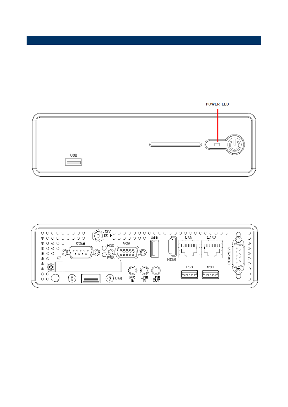
1.4 System Overview
1.4.1 Front & Rear View
Front View
Rear View
6 EPC-CDV Quick Reference Guide
Page 7
7
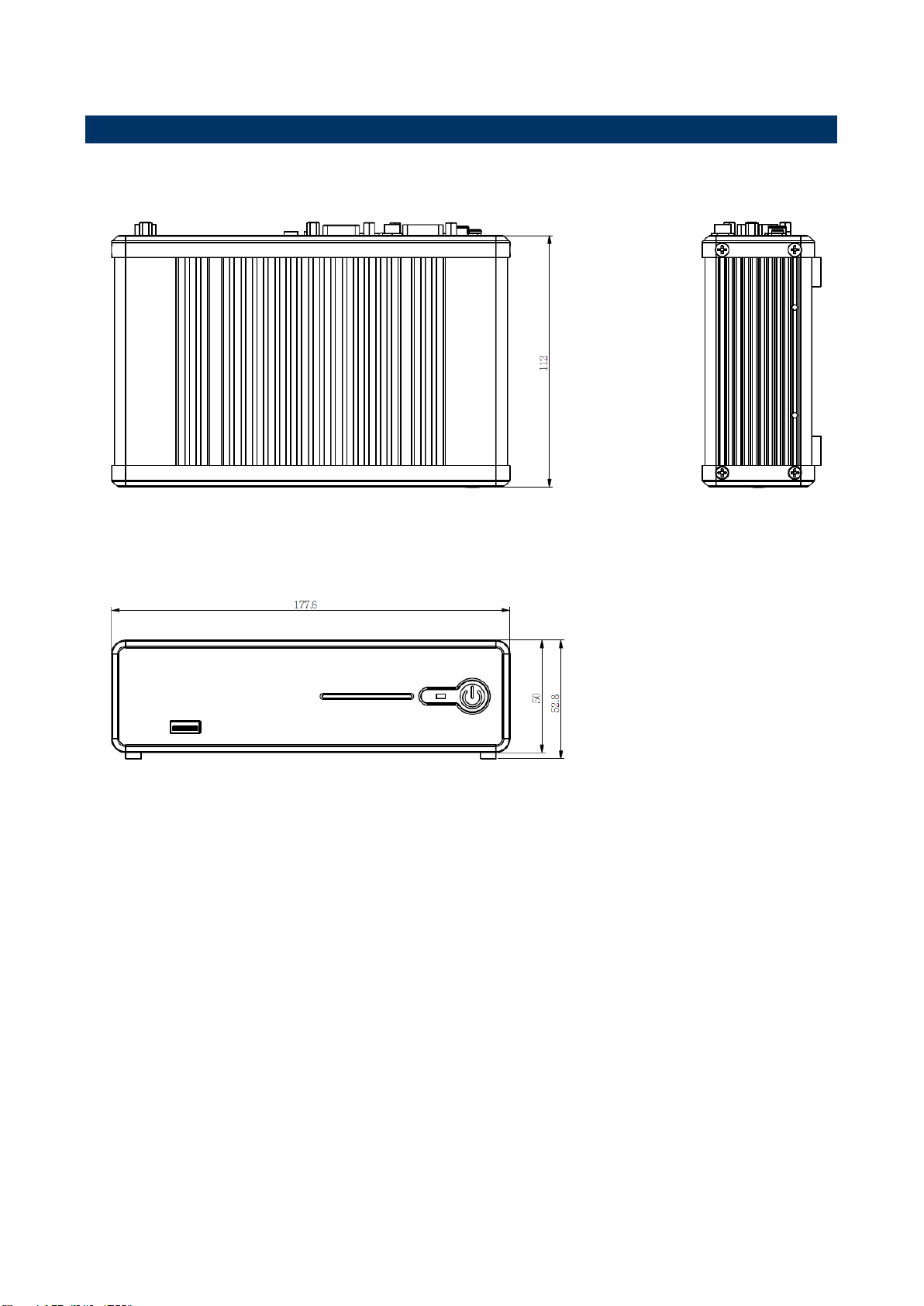
(Unit: mm)
1.5 System Dimensions
1.5.1 Top/ Front & Side (with rubber foot)
Quick Reference Guide
EPC-CDV Quick Reference Guide
Page 8
EPC-CDV
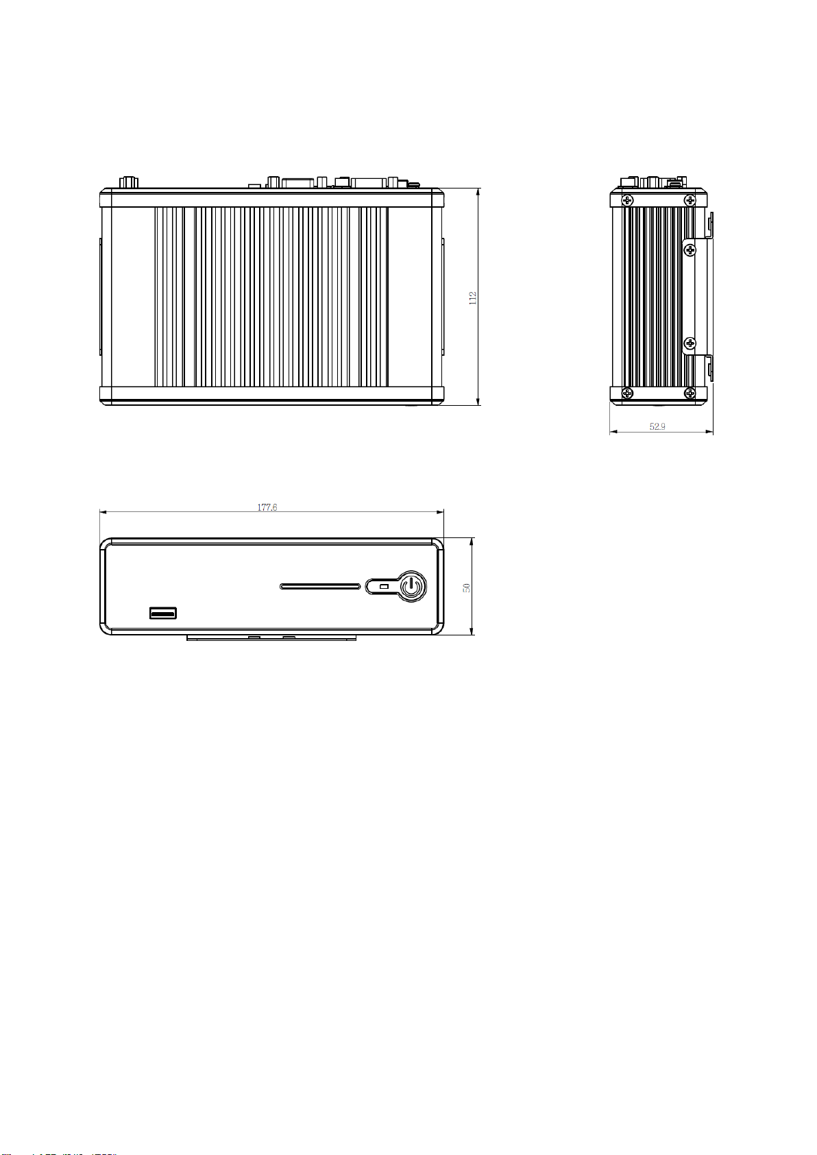
(Unit: mm)
1.5.2 Top/ Front & Side (with wallmount)
8 EPC-CDV Quick Reference Guide
Page 9

Quick Reference Guide
9
2. Hardware
Configuration
Please refer to ECM- CDV Quick Installation Guide or User’s Manual for
advanced information.
Note: If you need more information, please visit our website:
http://www.avalue.com.tw
EPC-CDV Quick Reference Guide
Page 10

EPC-CDV
Connectors
Label
Function
Note
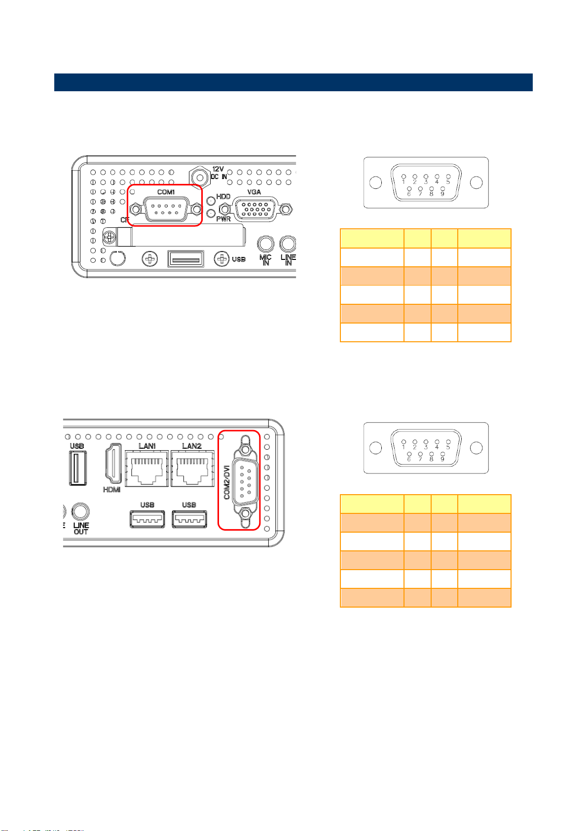
COM1
Serial port 1 connector
COM2/DVI
Serial port 2 connector
Compact Flash
Compact Flash card connector
Type I/II x 1
12V DC-IN
DC power-in connector
LAN1
RJ-45 Ethernet 1
LAN2
RJ-45 Ethernet 2
LINE IN
Line-in audio jack
LINE OUT
Line-out audio jack
MIC IN
Mic-in audio jack
HDD
HDD indicator
USB1~5
USB 1~5 connector
PWR
System power indicator
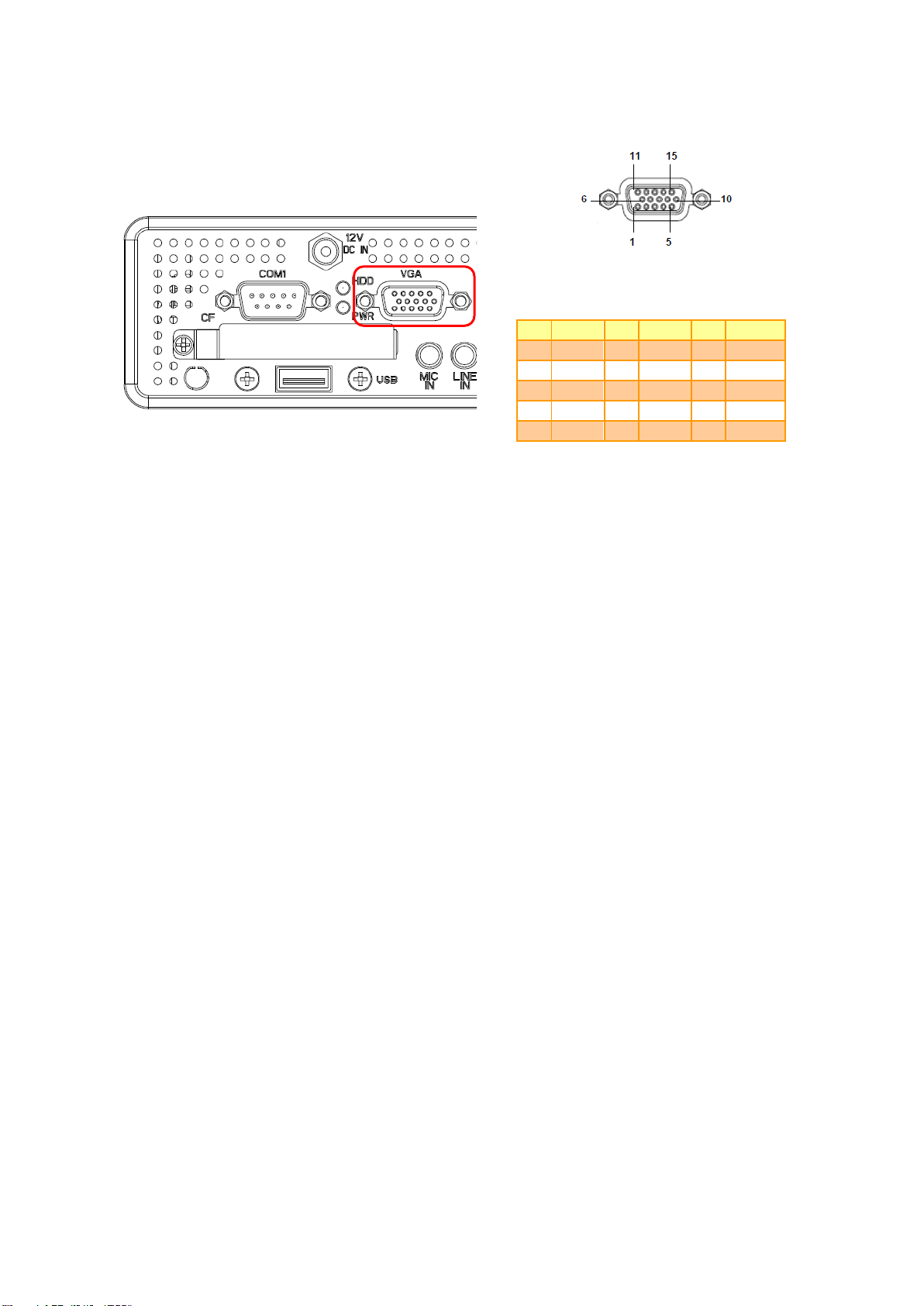
VGA
VGA connector
D-sub 15-pin, female
HDMI
HDMI connector
2.1 EPC-CDV connector list
10 EPC-CDV Quick Reference Guide
Page 11
11
Signal
PIN
PIN
Signal
DCDA#
1 2 RxDA
TxDA
3 4 DTRA#
GND
5 6 DSRA#
RTSA#
7 8 CTSA#
RIA#
9
10
NC
Signal
PIN
PIN
Signal
DCDB#
1 2 RxDB
TxDB
3 4 DTRB#
GND
5 6 DSRB#
RTSB#
7 8 CTSB#
RIB#
9
10
NC
2.2 EPC-CDV connector mapping
2.2.1 External Serial Port 1 connector (COM1)
Quick Reference Guide
2.2.2 External Serial Port 2 connector (COM2/DVI)
EPC-CDV Quick Reference Guide
Page 12
EPC-CDV
PIN
Signal
PIN
Signal
PIN
Signal
1 R 6
GND
11
NC 2 G 7 GND
12
DATA
3 B 8
GND
13
HSYNC
4
NC 9 +5V
14
VSYNC
5
GND
10
GND
15
CLK
2.2.3 VGA connector (VGA)
12 EPC-CDV Quick Reference Guide
Page 13
13
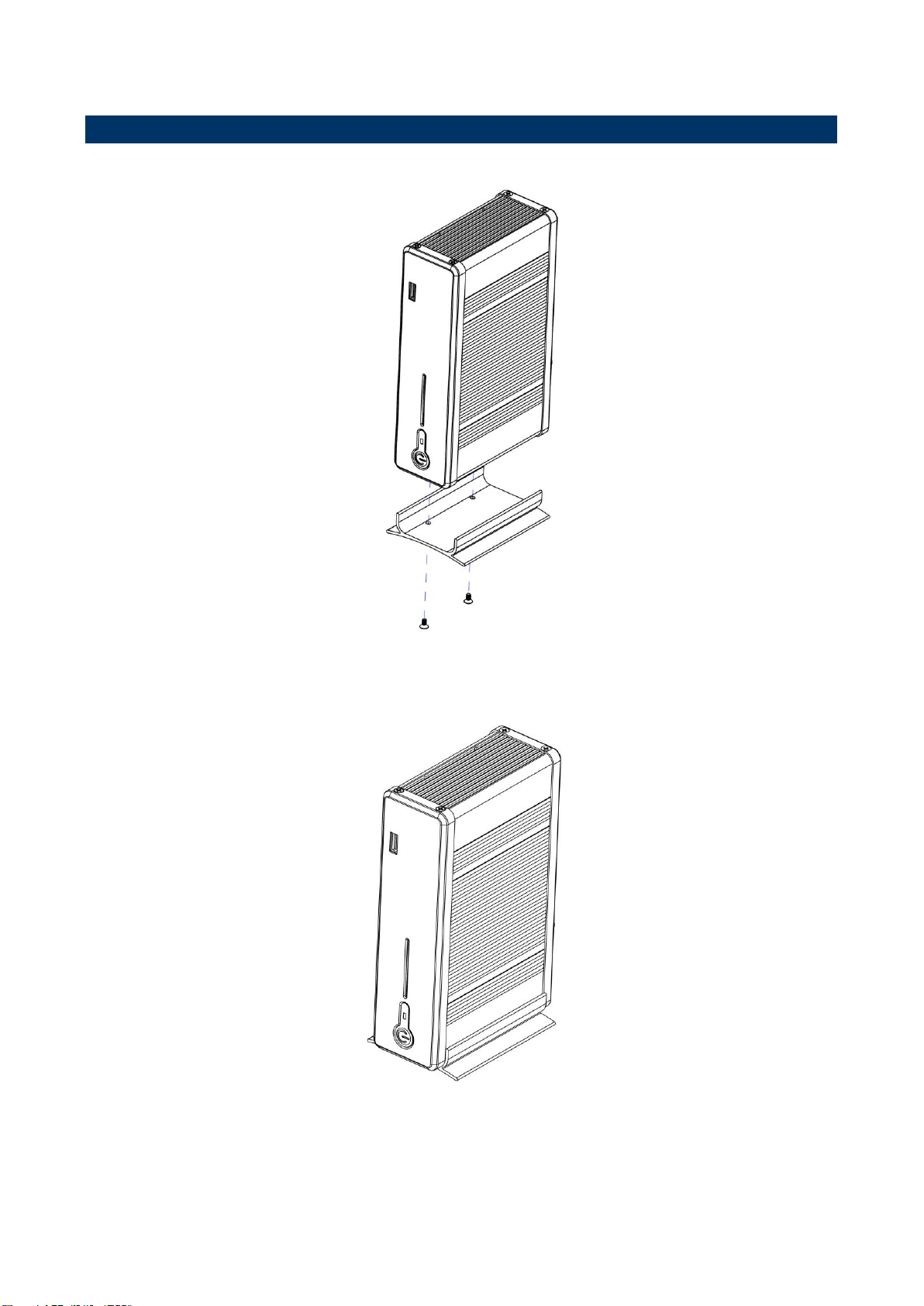
Step1.
Attach stand to your system by means of two screws.
Step2.
Stand installation completed.
2.3 Installing Aluminum Stand (EPC-CDV)
Quick Reference Guide
EPC-CDV Quick Reference Guide
Page 14
EPC-CDV
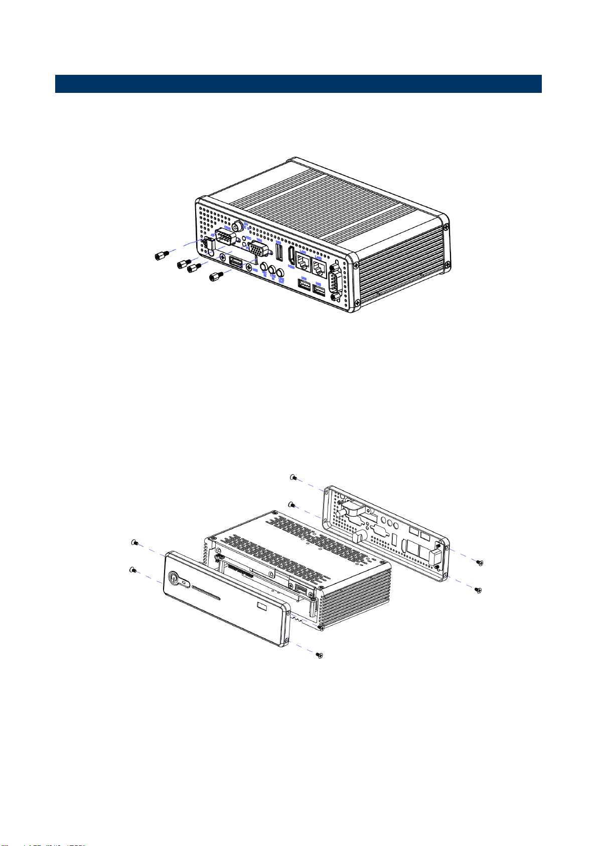
Step2.
Remove the 8 screws to disassemble your system front & back cover.
2.4 Installing Hard Disk & Memory (EPC-CDV)
Step1.
Remove the 4 screws from VGA and COM before removing back cover.
14 EPC-CDV Quick Reference Guide
Page 15
Quick Reference Guide
15
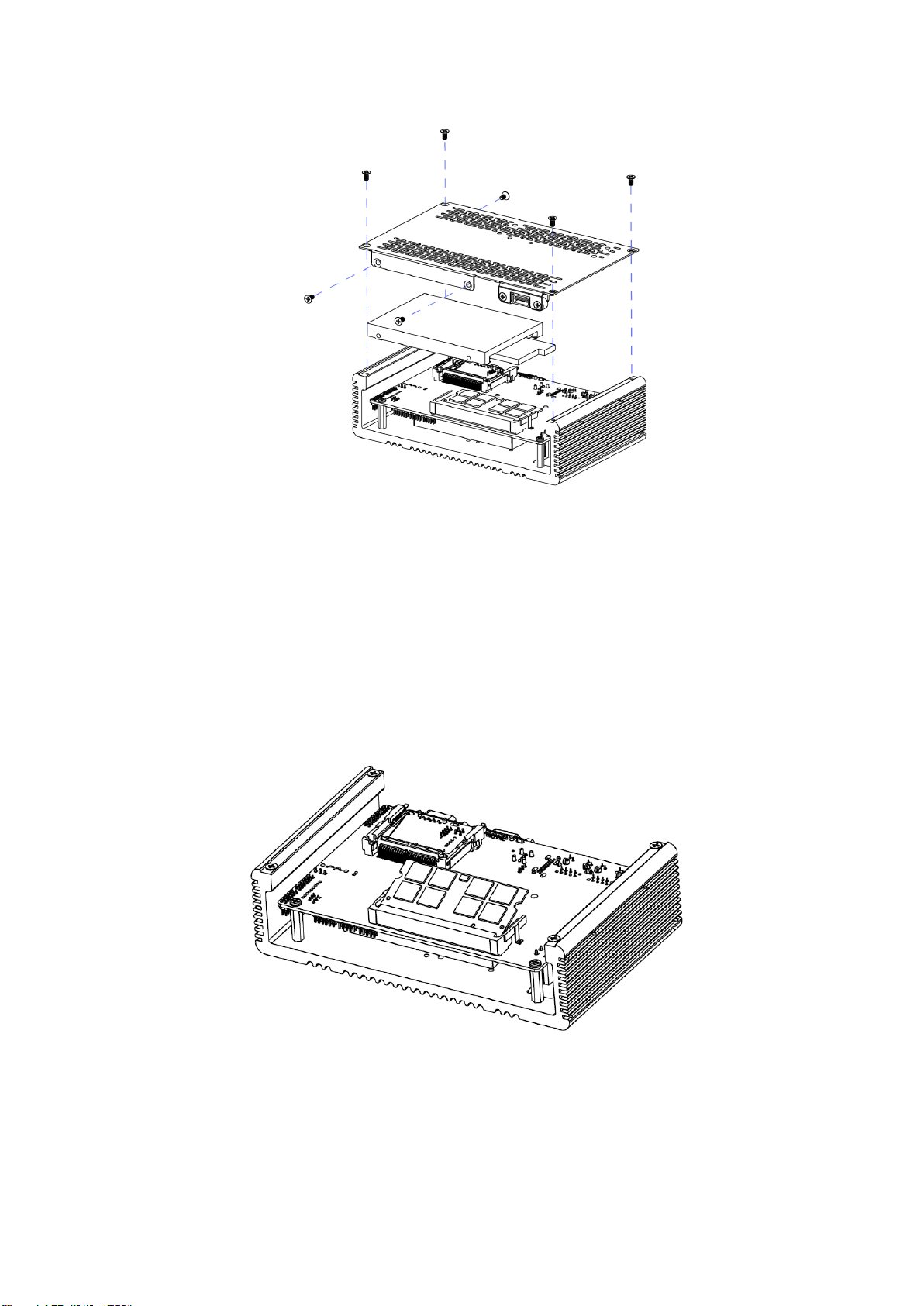
Step3. 1
For HDD installation, please remove 4 screws to detach top cover, HDD enclosure from board &
system assembly.
Step3. 2
Fix HDD using the 3 screws in the Accessory Kit.
Step4.1
Properly install the memory module and press until properly seated.
Step4.2
Re-assemble your system back through previous steps to complete the installation.
EPC-CDV Quick Reference Guide
Page 16
EPC-CDV
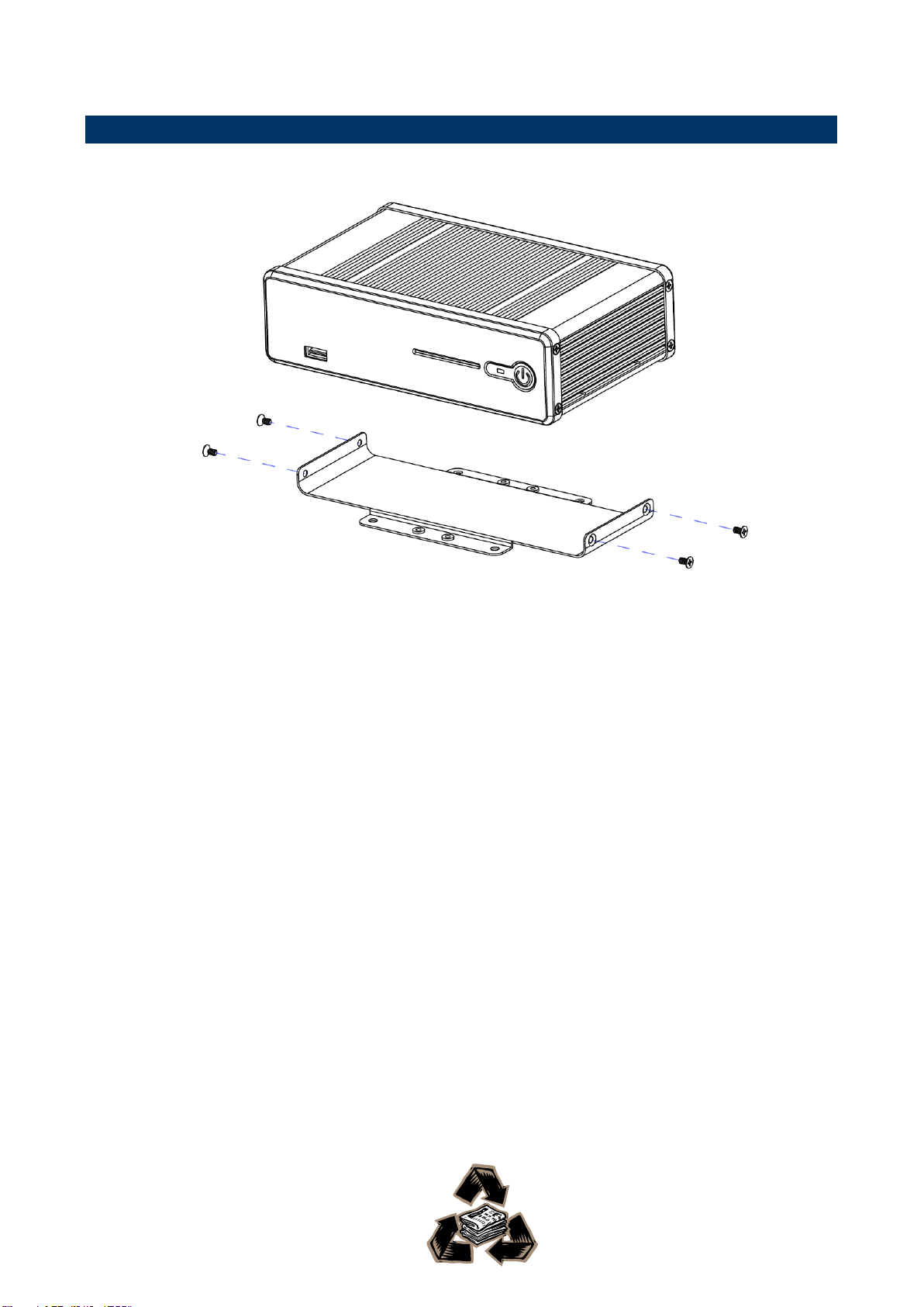
2.5 Installing Mounting Bracket (Optional)
Step 1. Fasten 4 screws on both sides of EPC Embedded System.
.
16 EPC-CDV Quick Reference Guide
 Loading...