


Avalue EMX-PNVB User Manual

EMX-PNVB
Intel® Atom™D525 Processor with ICH8M Chipset
Mini ITX Motherboard
User’s Manual
1st Ed – 15 October 2013
Part No. E2047PNVB00R

EMX-PNVB User’s Manual
FCC Statement
A Message to the Customer
THIS DEVICE COMPLIES WITH PART 15 FCC RULES. OPERATION IS
SUBJECT TO THE FOLLOWING TWO CONDITIONS:
(1) THIS DEVICE MAY NOT CAUSE HARMFUL INTERFERENCE.
(2) THIS DEVICE MUST ACCEPT ANY INTERFERENCE RECEIVED INCLUDING
INTERFERENCE THAT MAY CAUSE UNDESIRED OPERATION.
THIS EQUIPMENT HAS BEEN TESTED AND FOUND TO COMPLY WITH THE LIMITS
FOR A CLASS "A" DIGITAL DEVICE, PURSUANT TO PART 15 OF THE FCC RULES.
THESE LIMITS ARE DESIGNED TO PROVIDE REASONABLE PROTECTION AGAINST
HARMFUL INTERFERENCE WHEN THE EQUIPMENT IS OPERATED IN A
COMMERCIAL ENVIRONMENT. THIS EQUIPMENT GENERATES, USES, AND CAN
RADIATE RADIO FREQUENCY ENERGY AND, IF NOT INSTATLLED AND USED IN
ACCORDANCE WITH THE INSTRUCTION MANUAL, MAY CAUSE HARMFUL
INTERFERENCE TO RADIO COMMUNICATIONS.
OPERATION OF THIS EQUIPMENT IN A RESIDENTIAL AREA IS LIKELY TO CAUSE
HARMFUL INTERFERENCE IN WHICH CASE THE USER WILL BE REQUIRED TO
CORRECT THE INTERFERENCE AT HIS OWN EXPENSE.
Avalue Customer Services
Each and every Avalue’s product is built to the most exacting specifications to ensure
reliable performance in the harsh and demanding conditions typical of industrial
environments. Whether your new Avalue device is destined for the laboratory or the factory
floor, you can be assured that your product will provide the reliability and ease of operation
for which the name Avalue has come to be known.
Your satisfaction is our primary concern. Here is a guide to Avalue’s customer services. To
ensure you get the full benefit of our services, please follow the instructions below carefully.
Technical Support
We want you to get the maximum performance from your products. So if you run into
technical difficulties, we are here to help. For the most frequently asked questions, you can
easily find answers in your product documentation. These answers are normally a lot more
detailed than the ones we can give over the phone. So please consult the user’s manual
first.
To receive the latest version of the user’s manual; please visit our Web site at:
http://www.avalue.com.tw/
2 EMX-PNVB User’s Manual

EMX-PNVB User’s Manual
Content
1. Getting Started ............................................................................................................ 6
1.1 Safety Precautions .......................................................................................... 6
1.2 Packing List .................................................................................................... 6
1.3 Document Amendment History ....................................................................... 7
1.4 Manual Objectives .......................................................................................... 8
1.5 Specifications ................................................................................................. 9
1.6 Architecture Overview—Block Diagram........................................................ 11
2. Hardware Configuration ........................................................................................... 12
2.1 Product Overview ......................................................................................... 13
2.2 Installation Procedure ................................................................................... 14
2.3 Jumper and Connector List .......................................................................... 15
2.4 Setting Jumpers & Connectors ..................................................................... 17
2.4.1 Clear CMOS (JBAT1) ............................................................................ 17
2.4.2 Keyboard power select jumper (JKB1) .................................................. 17
2.4.3 Jumper for COM2 or IR selection (JIR1~2) ........................................... 18
2.4.4 Jumper for LVDS PWR selection (JP1) ................................................. 18
2.4.5 Jumper for MPCIE selection (JS1~2) .................................................... 19
2.4.6 Jumper for MPCIE PWR selection (JS3) ............................................... 19
2.4.7 Serial port 1~6 or RI, USE JC11/21/31/41/51/61 PIN 9 selector
(JC12/22/32/42/52/62) ......................................................................................... 20
2.4.8 Jumper for Serial port 1~6 pin9 power selection (JC11/21/31/41/51/61)
20
2.4.9 General Purpose I/O (JGPIO1) ............................................................. 21
2.4.10 Front Panel Switches (FPANEL1) ......................................................... 21
2.4.11 LVDS connector (LVDS1) ..................................................................... 22
2.4.12 VGA connector (JVGA2) ....................................................................... 23
2.4.13 Inverter connector (INCN1) ................................................................... 23
2.4.14 Front Panel Audio Connection Header (F_AUDIO) ............................... 24
2.4.15 Serial port 2~6 connector (COM2~6) .................................................... 25
2.4.16 USB connector 1~2 (FUSB1~2) ............................................................ 25
2.4.17 Sony/Philips Digital Interface (JSPDIF1) ............................................... 26
2.4.18 System Fan connector (SFAN1) ........................................................... 26
2.4.3 IDE connector (IDE1) ............................................................................ 27
2.4.20 Keyboard & Mouse connector (JKB_MS) .............................................. 28
2.4.21 System Management Bus controller (JSM_BUS) .................................. 28
2.4.22 ATX Power connector (ATXPWR1) ....................................................... 29
EMX-PNVB User’s Manual 3

EMX-PNVB User’s Manual
3.BIOS Setup .................................................................................................................... 30
3.1 Introduction ................................................................................................... 31
3.2 Starting Setup ............................................................................................... 31
3.3 Using Setup .................................................................................................. 32
3.4 Getting Help ................................................................................................. 33
3.5 In Case of Problems ..................................................................................... 33
3.6 BIOS setup ................................................................................................... 34
3.6.1 Main Menu ............................................................................................ 34
3.6.1.1 System Date .................................................................................. 34
3.6.1.2 System Time .................................................................................. 34
3.6.2 Advanced BIOS settings ....................................................................... 35
3.6.2.1 CPU Configuration ......................................................................... 35
3.6.2.2 IDE Configuration ........................................................................... 36
3.6.2.3 USB Configuration ......................................................................... 37
3.6.2.4 WatchDogTimer Setting ................................................................. 38
3.6.2.5 COM/LPT Configuration ................................................................. 38
3.6.2.5.1 Serial Port 1 Configuration ................................................. 39
3.6.2.5.2 Serial Port 2 Configuration ................................................. 40
3.6.2.5.3 Serial Port 3 Configuration ................................................. 41
3.6.2.5.4 Serial Port 4 Configuration ................................................. 42
3.6.2.5.5 Serial Port 5 Configuration ................................................. 43
3.6.2.5.6 Serial Port 6 Configuration ................................................. 44
3.6.2.5.7 Parallel Port Configuration ................................................. 45
3.6.2.6 HW Monitor .................................................................................... 46
3.6.2.7 Power Management ....................................................................... 46
3.6.3 Chipset ..................................................................................................... 47
3.6.3.1 North Bridge ................................................................................... 48
3.6.3.2 South Bridge .................................................................................. 49
3.6.4 Boot settings ......................................................................................... 50
3.6.5 Security ................................................................................................. 50
3.6.5.1 Administrator Password ................................................................. 51
3.6.6 Save & Exit ............................................................................................ 51
3.6.6.1 Restore Defaults ............................................................................ 52
3.6.6.2 Save Changes and Reset .............................................................. 52
3.6.6.3 Discard Changes and Reset ........................................................ 52
3.6.6.4 Save Changes.............................................................................. 52
3.6.6.5 Discard Changes .......................................................................... 52
4. Drivers Installation....................................................................................................... 53
4.1 Install Chipset Driver .................................................................................... 54
4.2 Install VGA Driver ......................................................................................... 55
4 EMX-PNVB User’s Manual

EMX-PNVB User’s Manual
4.3 Install LAN Driver (For Realtek 8111E Gigabit Ethernet) ............................. 57
4.4 Install Audio Driver (For Realtek ALC661 HD Audio) ................................... 58
5. Mechanical Drawing .................................................................................................... 59
EMX-PNVB User’s Manual 5
EMX-PNVB User’s Manual
1. Getting Started
1.1 Safety Precautions
Warning!
Always completely disconnect the power cord from your
chassis whenever you work with the hardware. Do not
make connections while the power is on. Sensitive
electronic components can be damaged by sudden power
surges. Only experienced electronics personnel should
open the PC chassis.
Caution!
Always ground yourself to remove any static charge before
touching the CPU card. Modern electronic devices are very
sensitive to static electric charges. As a safety precaution,
use a grounding wrist strap at all times. Place all electronic
components in a static-dissipative surface or static-shielded
bag when they are not in the chassis.
Always note that improper disassembling action could cause damage to the
motherboard. We suggest not removing the heatsink without correct
instructions in any circumstance. If you really have to do this, please contact
us for further support.
1.2 Packing List
Before you begin installing your single board, please make sure that the
following materials have been shipped:
Quick Installation Guide X 1
Driver/Utility CD X 1
Serial ATA Signal Cable X 1
COM Port X 1
Screw X 2
Motherboard X 1
Front Audio cable X 1
IO Shield X 1
6 EMX-PNVB User’s Manual

EMX-PNVB User’s Manual
Revision
Date
By
Comment
1st
October 2013
Avalue
Initial Release
1.3 Document Amendment History
EMX-PNVB User’s Manual 7

EMX-PNVB User’s Manual
1.4 Manual Objectives
This manual describes in details Avalue Technology EMX-PNVB Single Board.
We have tried to include as much information as possible but we have not duplicated
information that is provided in the standard IBM Technical References, unless it proved to
be necessary to aid in the understanding of this board.
We strongly recommend that you study this manual carefully before attempting to set up
EMX-PNVB series or change the standard configurations. Whilst all the necessary
information is available in this manual we would recommend that unless you are confident,
you contact your supplier for guidance.
If you have any suggestions or find any errors regarding this manual and want to inform us
of these, please contact our Customer Service department with the relevant details.
8 EMX-PNVB User’s Manual
EMX-PNVB User’s Manual
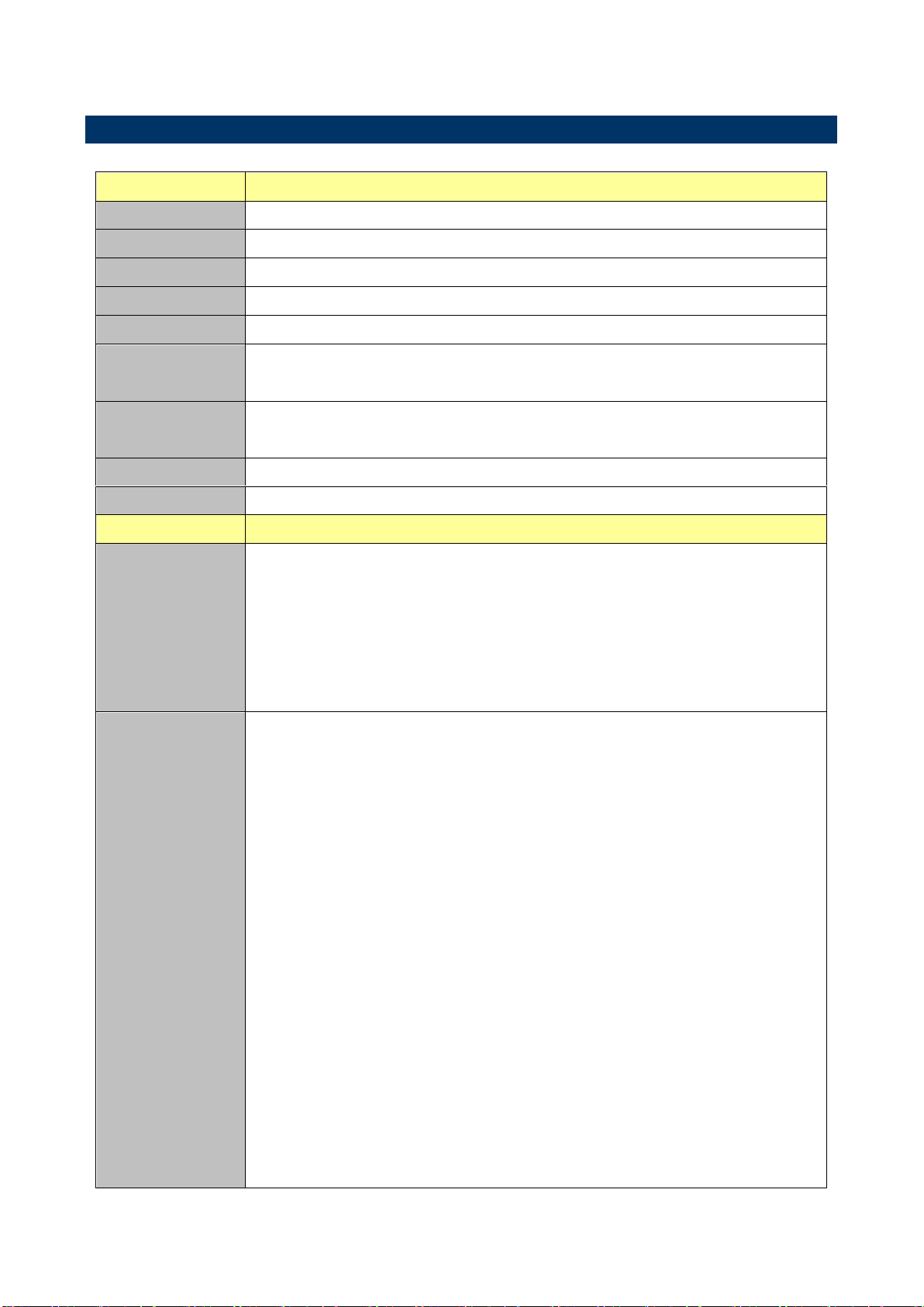
System
CPU
Intel® Atom™ Processor D525 Processor
BIOS
AMI uEFI BIOS, 16Mbit SPI Flash ROM
System Chipset
Intel® ICH8M
I/O Chip
Winbond W83627UHG
System Memory
1 x 204-pin DDR3 800/1066/1333 MHz SODIMMs, up to 4GB
Watchdog Timer
H/W Reset, 1sec. – 65535sec./min.
1sec. or 1min. step
H/W Status
Monitor
CPU & system temperature monitoring
Voltages monitoring
Buzzer
Buzzer onboard
Expansion
1 x Mini PCI-e (Mini PCI-e and mSATA SSD is Switchable Through Jumper)
I/O
Rear Side External
I/O Connector
2 x RJ-45 with dual deck USB2.0 connector
1 x VGA
1 x COM support RS-232 connector, Pin 9 with / +5V&12V supported
1 x Printer port
1 x Keyboard PS2 and 1 x Mouse PS2
1 x Mic-In and 1 x Line-out
Internal I/O
Connector
Storage:
- 2 x SATA II connector
COM:
- COM2~6: support RS-232 connector, Pin 9 with / +5V&+12V supported
1 x Mini PCI-e slot ( switchable to support mSATA or mini PCIe)
2 x 2 x 5 pin, pitch 2.54mm connector for USB 2.0
1 x 1 x 4 pin, pitch 2.54mm CPU fan connector
1 x horizontal type battery connector
1 x 2 x 8 pin, pitch 2.54mm connector for front panel
1 x 2 x 10 pin ATX power connector
1 x 2 x 20 pin, pitch 1.25mm connector for LVDS
1 x 3 pin, pitch 2.54mm connector for LVDS power
1 x 5 pin, pitch 2.54mm connector for Inverter
1 x 3 pin, pitch 2.54mm connector for Inverter power
1 x 2 x 5 pin, pitch 2.54mm connector for front Audio
1 x 2 x 22 pin, pitch 2.00mm connector for IDE
5 x 2 x 5 pin, pitch 2.00mm connector for COM port
1.5 Specifications
EMX-PNVB User’s Manual 9
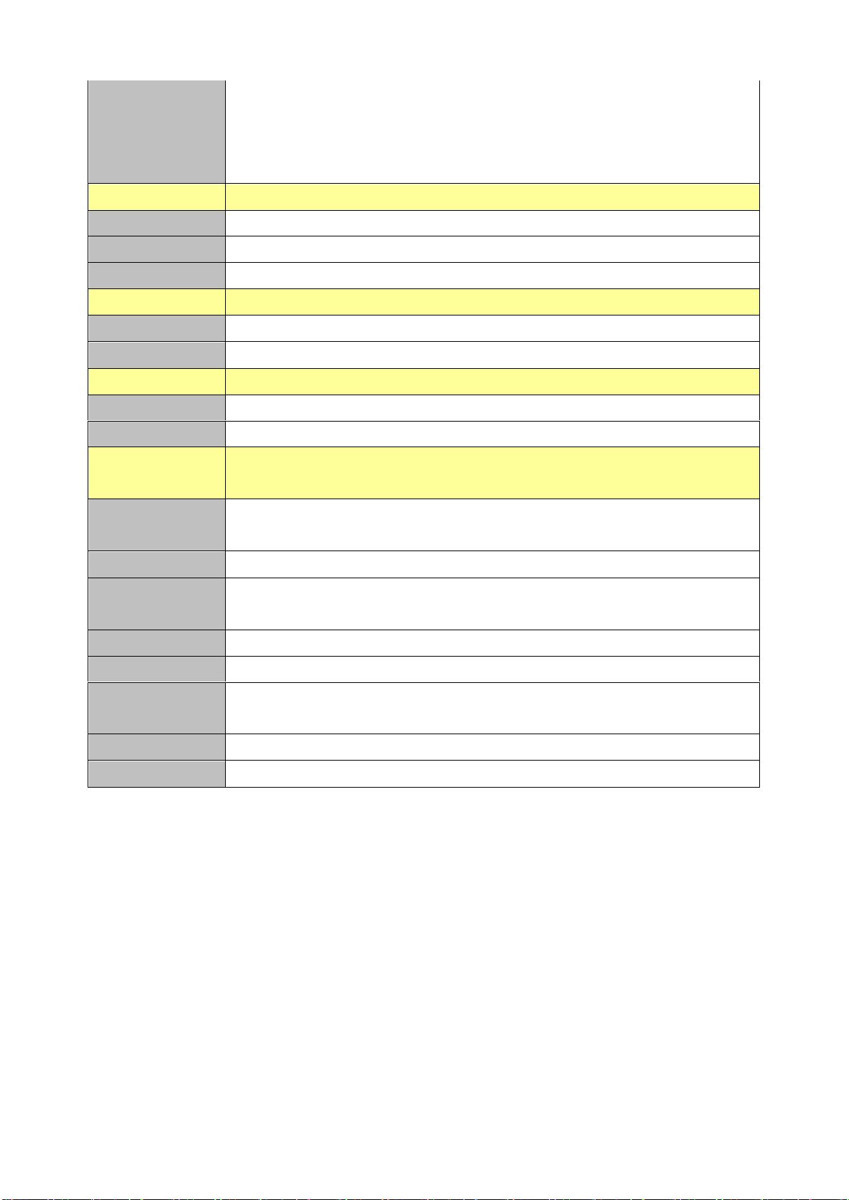
EMX-PNVB User’s Manual
1 x 2 x 5 pin, pitch 2.54mm connector for VGA
1 x 2 x 5 pin, pitch 2.54mm connector for Keyboard & Mouse
1 x 2 x 6 pin, pitch 2.54mm connector for 8 bit GPIO
1 x 3 pin, pitch 2.54mm connector for SPDIF
Display
Chipset
Intel ICH8M integrated
Resolution
VGA: 2048 x 1536
LVDS
1CH 18 bits LVDS 1366 x 768
Audio
Chipset
Realtek ALC661 HD Audio Decoding Controller
Audio Interface
Mic-In, Line-In
Ethernet
Chipset
2 x Realtek RTL8111E PCI-Express Gigabit Ethernet
Ethernet Interface
10/100/1000 Gigabit Ethernet
Mechanical &
Environmental
Power
Requirement
+12V / +5V / 5VSB /+3.3V
Power Type
ATX mode
ACPI
Single power ATX Support S0,S1, S3, S4, S5
ACPI 3.0 Compliant
Operating Temp.
0°C ~60°C
Storage Temp.
-40°C ~75°C
Operating
Humidity
0%~90% relative humidity, non-condensing
Size (L x W)
6.7" x 6.7" (170mm x 170mm)
Weight
0.40 kg
10 EMX-PNVB User’s Manual
EMX-PNVB User’s Manual
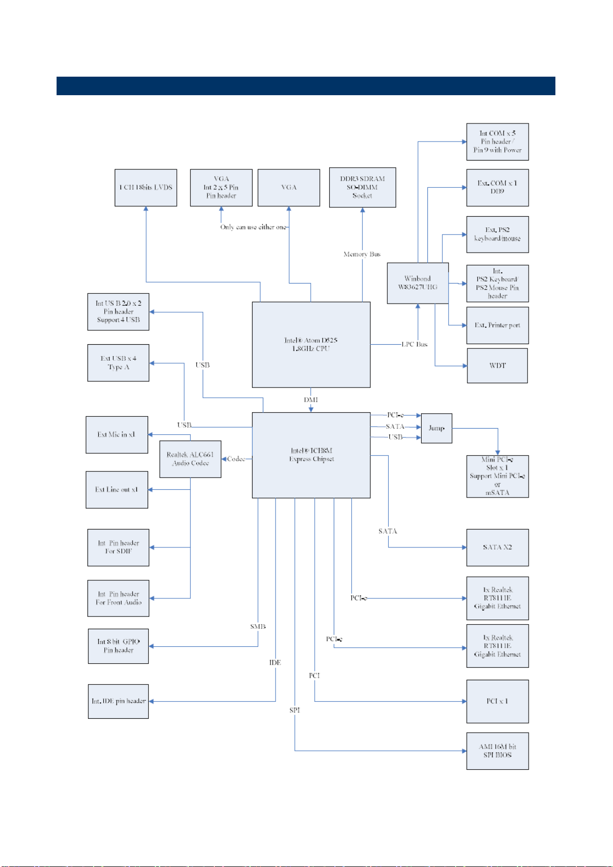
1.6 Architecture Overview—Block Diagram
The following block diagram shows the architecture and main components of EMX-PNVB.
EMX-PNVB User’s Manual 11

EMX-PNVB User’s Manual
2. Hardware
Configuration
12 EMX-PNVB User’s Manual
EMX-PNVB User’s Manual
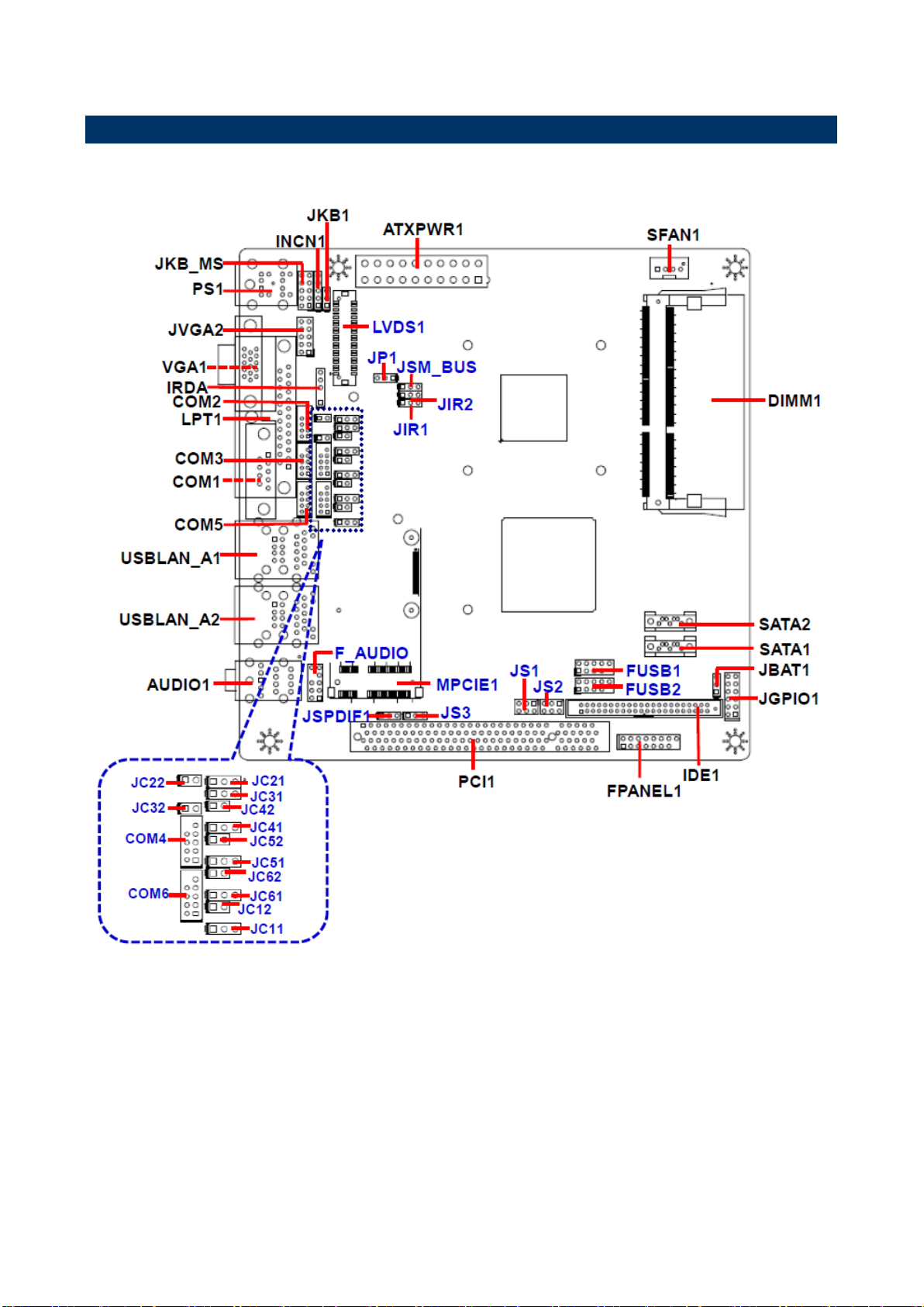
2.1 Product Overview
EMX-PNVB User’s Manual 13

EMX-PNVB User’s Manual
2.2 Installation Procedure
This chapter explains you the instructions of how to setup your system.
1. Turn off the power supply.
2. Insert the DIMM module (be careful with the orientation).
3. Insert all external cables for hard disk, floppy, keyboard, mouse, USB etc. except for flat
panel. A CRT monitor must be connected in order to change BIOS settings to support flat
panel.
4. Connect power supply to the board via the ATX Power.
5. Turn on the power.
6. Enter the BIOS setup by pressing the delete key during boot up. Use the "Save & Exit \
Restore Defaults" feature.
7. If TFT panel display is to be utilized, make sure the panel voltage is correctly set before
connecting the display cable and turning on the power.
14 EMX-PNVB User’s Manual
EMX-PNVB User’s Manual
Jumpers
Label
Function
Note
JP1
Jumper for LVDS PWR selection
1 x 3 header, pitch 2.54 mm
JKB1
Keyboard power select jumper
1 x 3 header, pitch 2.54 mm
JIR1~2
Jumper for COM2 or IR selection.
The IR function can’t be used.
1 x 3 header, pitch 2.54 mm
JC12/22/32/42/52/62
Serial port 1~6 or RI, USE
JC11/21/31/41/51/61 PIN 9 selector
1 x 2 header, pitch 2.54 mm
JBAT1
Clear CMOS
1 x 3 header, pitch2.54 mm
JS1~2
Jumper for MPCIE & MSATA selection
2 x 3 header, pitch 2.54 mm
JS3
Jumper for MPCIE PWR selection
1 x 3 header, pitch 2.54 mm
2.3 Jumper and Connector List
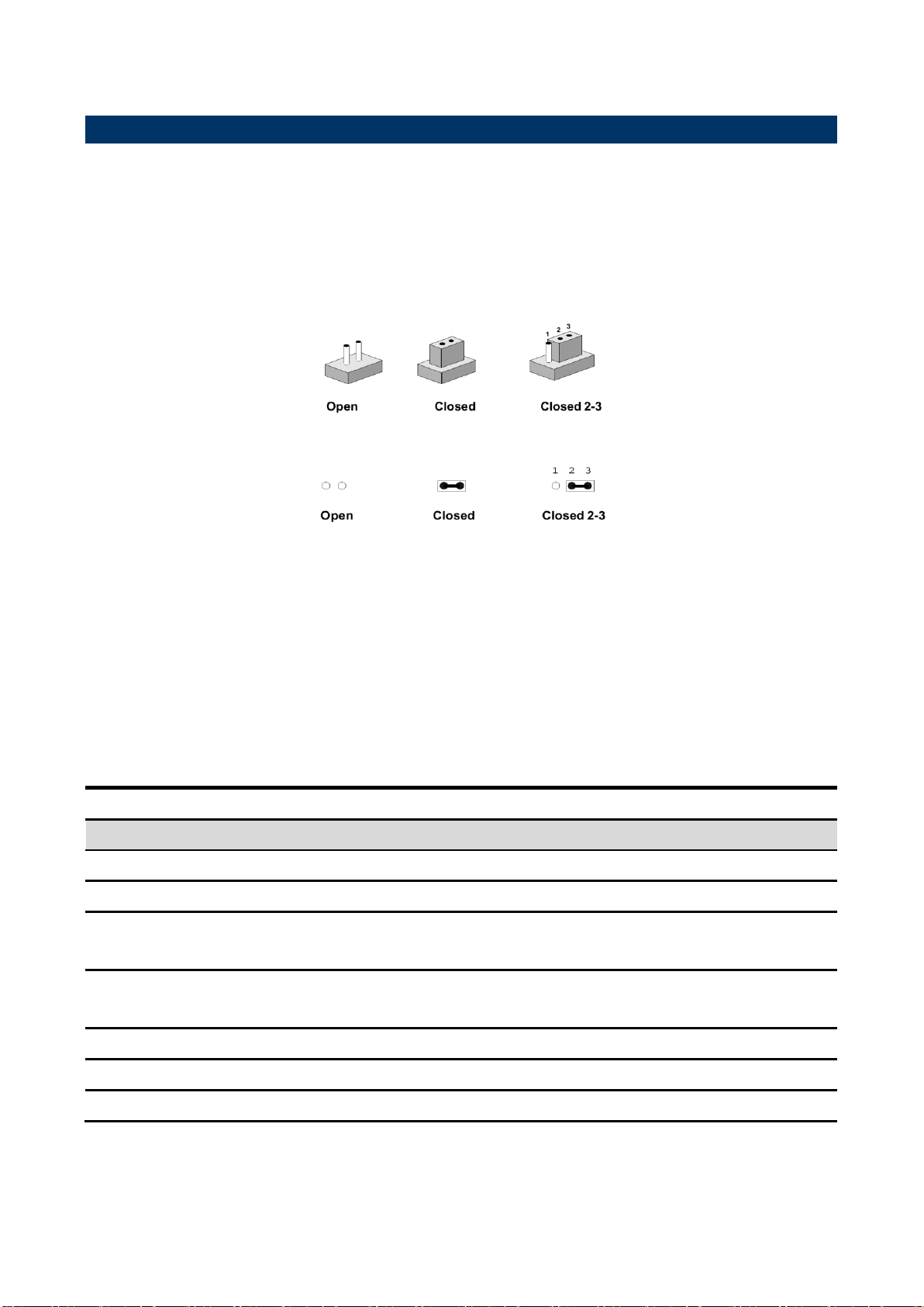
You can configure your board to match the needs of your application by setting jumpers. A
jumper is the simplest kind of electric switch.
It consists of two metal pins and a small metal clip (often protected by a plastic cover) that
slides over the pins to connect them. To “close” a jumper you connect the pins with the clip.
To “open” a jumper you remove the clip. Sometimes a jumper will have three pins, labeled 1,
2, and 3. In this case, you would connect either two pins.
The jumper settings are schematically depicted in this manual as follows:
A pair of needle-nose pliers may be helpful when working with jumpers.
Connectors on the board are linked to external devices such as hard disk drives, a
keyboard, or floppy drives. In addition, the board has a number of jumpers that allow you to
configure your system to suit your application.
If you have any doubts about the best hardware configuration for your application, contact
your local distributor or sales representative before you make any changes.
The following tables list the function of each of the board’s jumpers and connectors.
EMX-PNVB User’s Manual 15

EMX-PNVB User’s Manual
Connectors
Label
Function
Note
FPANEL1
Front Panel Switches
2 x 8 header, pitch 2.54 mm
MPCIE1
PCIE signal selector
PCI1
PCI slot
COM1
Serial port 1 connector
COM2~6
Serial port 2~6 connector
2 x 5 header, pitch 2.00 mm
JGPIO1
General Purpose I/O
2 x 6 header, pitch 2.54 mm
LVDS1
LVDS connector
2 x 20 wafer, pitch 1.25 mm
SATA1~2
Serial ATA connector 1~2
USB LAN_A1~2
USB & LAN port 1~2
F_USB1~2
USB connector 1~2
2 x 5 header, pitch 2.54 mm
SFAN1
System Fan connector
1 x 4 wafer, pitch 2.54 mm
LPT1
Printer
DIMM1
DDR3 SODIMM socket
VGA1
VGA connector
JVGA2
VGA connector
2 x 5 header, pitch 2.54 mm
PS1
PS/2 Keyboard & Mouse connector
F_AUDIO
Front Panel Audio Connection Header
2 x 5 header, pitch 2.54 mm
JSPDIF1
Sony/Philips Digital Interface
1 x 3 header, pitch 2.54 mm
IRDA
IRDA connector (not supported)
1 x 5 header, pitch 2.54 mm
IDE1
IDE connector
2 x 22 header, pitch 2.00 mm
ATXPWR1
ATX Power connector
2 x 10 wafer, pitch 4.20 mm
INCN1
Inverter connector
1 x 5 header, pitch 2.54 mm
JSM_BUS
System Management Bus controller
1 x 3 header, pitch 2.54 mm
JC11/21/31/41/51/61
Jumper for Serial port 1~6 pin9 power
selection
1 x 3 header, pitch 2.54 mm
JKB_MS
Keyboard & Mouse connector
2 x 5 header, pitch 2.54 mm
AUDIO1
Line-Out & Mic-In connector
16 EMX-PNVB User’s Manual
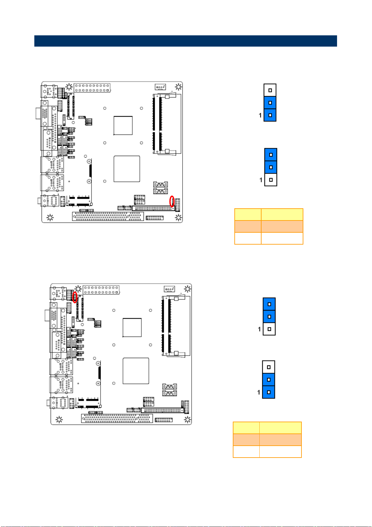
EMX-PNVB User’s Manual
* Default
Normal*
Clear CMOS
Pin
Define
1-2
Normal
2-3
Clear CMOS
* Default
Disabled*
Enabled
Pin
Define
1-2
Disabled
2-3
Enabled
2.4 Setting Jumpers & Connectors
2.4.1 Clear CMOS (JBAT1)
2.4.2 Keyboard power select jumper (JKB1)
EMX-PNVB User’s Manual 17
EMX-PNVB User’s Manual
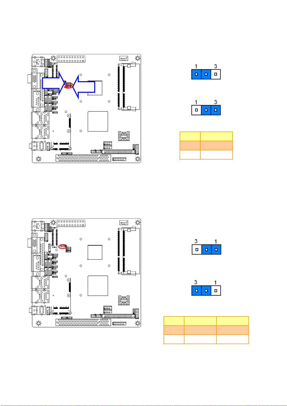
* Default
COM2*
IR
Pin
Define
1-2
COM2
2-3
IR
Note: IR is not functional.
* Default
3.3V*
5V
Pin
Define
Max current
1-2
3.3V
1A
2-3
5V
1A
JIR2
JIR1
2.4.3 Jumper for COM2 or IR selection (JIR1~2)
2.4.4 Jumper for LVDS PWR selection (JP1)
18 EMX-PNVB User’s Manual
EMX-PNVB User’s Manual
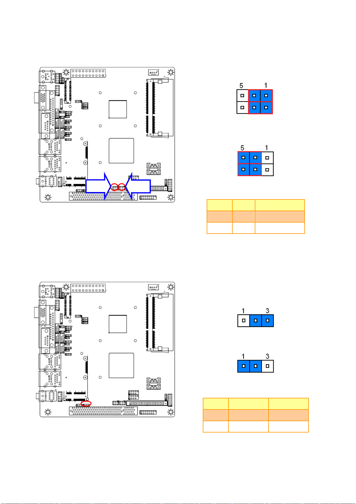
* Default
M-SATA*
MINIPCIE
Pin
Pin
Define
1-3
2-4
M-SATA
3-5
4-6
MINIPCIE
* Default
3.3V*
GND
Pin
Define
Max current
2-3
GND
1-2
3.3V
1A
JS2
JS1
2.4.5 Jumper for MPCIE selection (JS1~2)
2.4.6 Jumper for MPCIE PWR selection (JS3)
EMX-PNVB User’s Manual 19