

Avalue EMX-PNVB User Manual

EMX-PNVB
Intel® Atom™D525 Processor with ICH8M Chipset
Mini ITX Motherboard
Quick Installation Guide
1st Ed – 11 September 2013
Part No. E2017PNVB00R

EMX-PNVB Quick Installation Guide
FCC Statement
A Message to the Customer
THIS DEVICE COMPLIES WITH PART 15 FCC RULES. OPERATION IS
SUBJECT TO THE FOLLOWING TWO CONDITIONS:
(1) THIS DEVICE MAY NOT CAUSE HARMFUL INTERFERENCE.
(2) THIS DEVICE MUST ACCEPT ANY INTERFERENCE RECEIVED INCLUDING
INTERFERENCE THAT MAY CAUSE UNDESIRED OPERATION.
THIS EQUIPMENT HAS BEEN TESTED AND FOUND TO COMPLY WITH THE LIMITS
FOR A CLASS "A" DIGITAL DEVICE, PURSUANT TO PART 15 OF THE FCC RULES.
THESE LIMITS ARE DESIGNED TO PROVIDE REASONABLE PROTECTION AGAINST
HARMFUL INTERFERENCE WHEN THE EQUIPMENT IS OPERATED IN A
COMMERCIAL ENVIRONMENT. THIS EQUIPMENT GENERATES, USES, AND CAN
RADIATE RADIO FREQUENCY ENERGY AND, IF NOT INSTATLLED AND USED IN
ACCORDANCE WITH THE INSTRUCTION MANUAL, MAY CAUSE HARMFUL
INTERFERENCE TO RADIO COMMUNICATIONS.
OPERATION OF THIS EQUIPMENT IN A RESIDENTIAL AREA IS LIKELY TO CAUSE
HARMFUL INTERFERENCE IN WHICH CASE THE USER WILL BE REQUIRED TO
CORRECT THE INTERFERENCE AT HIS OWN EXPENSE.
Avalue Customer Services
Each and every Avalue’s product is built to the most exacting specifications to ensure
reliable performance in the harsh and demanding conditions typical of industrial
environments. Whether your new Avalue device is destined for the laboratory or the factory
floor, you can be assured that your product will provide the reliability and ease of operation
for which the name Avalue has come to be known.
Your satisfaction is our primary concern. Here is a guide to Avalue’s customer services. To
ensure you get the full benefit of our services, please follow the instructions below carefully.
Technical Support
We want you to get the maximum performance from your products. So if you run into
technical difficulties, we are here to help. For the most frequently asked questions, you can
easily find answers in your product documentation. These answers are normally a lot more
detailed than the ones we can give over the phone. So please consult the user’s manual
first.
To receive the latest version of the user’s manual; please visit our Web site at:
http://www.avalue.com.tw/
2 EMX-PNVB Quick Installation Guide
EMX-PNVB Quick Installation Guide
1. Getting Started
1.1 Safety Precautions
Warning!
Always completely disconnect the power cord from your
chassis whenever you work with the hardware. Do not
make connections while the power is on. Sensitive
electronic components can be damaged by sudden power
surges. Only experienced electronics personnel should
open the PC chassis.
Caution!
Always ground yourself to remove any static charge before
touching the CPU card. Modern electronic devices are very
sensitive to static electric charges. As a safety precaution,
use a grounding wrist strap at all times. Place all electronic
components in a static-dissipative surface or static-shielded
bag when they are not in the chassis.
Always note that improper disassembling action could cause damage to the
motherboard. We suggest not removing the heatsink without correct
instructions in any circumstance. If you really have to do this, please contact
us for further support.
1.2 Packing List
Before you begin installing your single board, please make sure that the
following materials have been shipped:
Quick Installation Guide X 1
Driver/Utility CD X 1
Serial ATA Signal Cable X 1
COM Port X 1
Screw X 2
Motherboard X 1
Front Audio cable X 1
IO Shield X 1
EMX-PNVB Quick Installation Guide 3

EMX-PNVB Quick Installation Guide
2. Hardware
Configuration
4 EMX-PNVB Quick Installation Guide
EMX-PNVB Quick Installation Guide
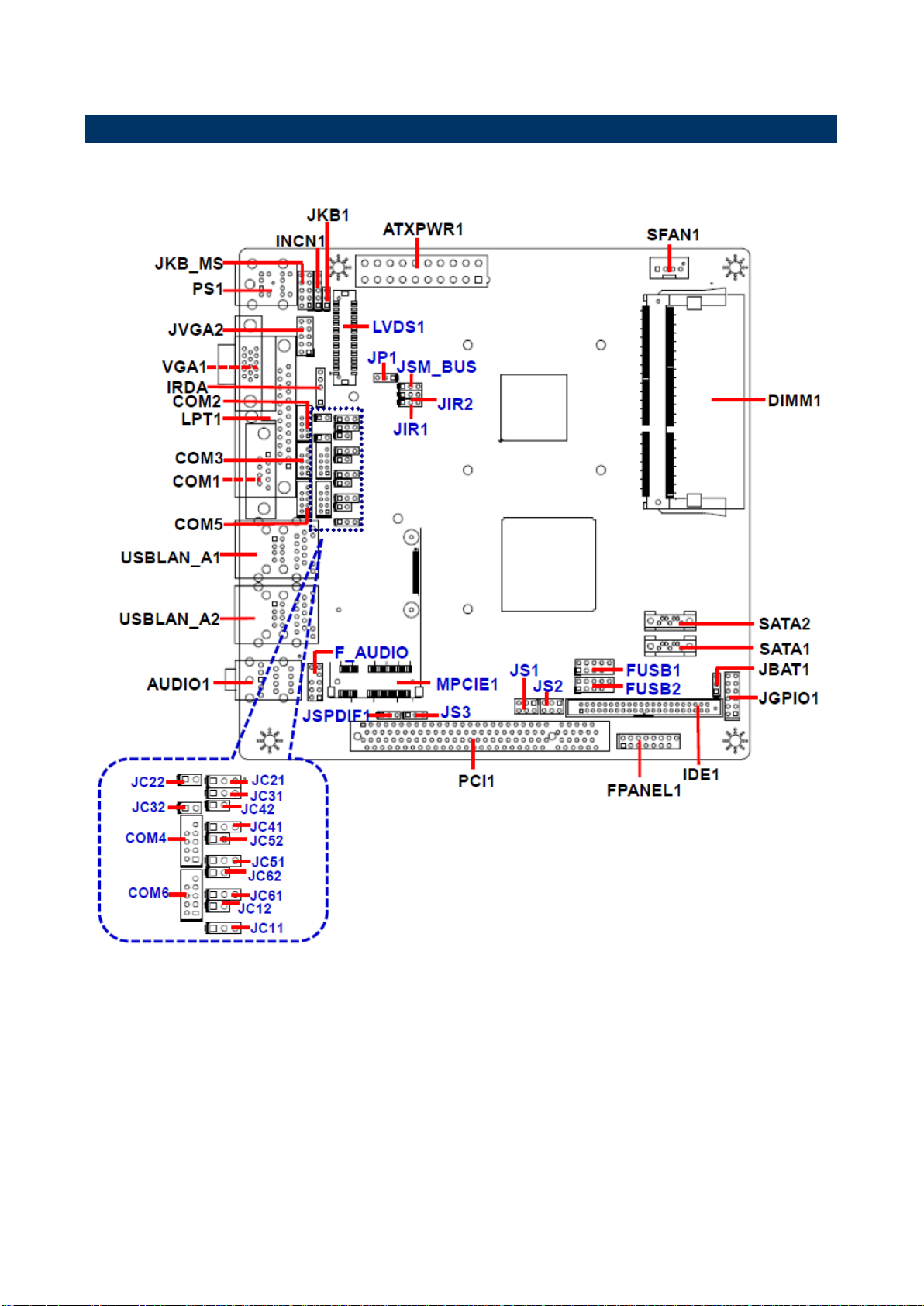
2.1 Product Overview
EMX-PNVB Quick Installation Guide 5
EMX-PNVB Quick Installation Guide
Jumpers
Label
Function
Note
JP1
Jumper for LVDS PWR selection
1 x 3 header, pitch 2.54 mm
JKB1
Keyboard power select jumper
1 x 3 header, pitch 2.54 mm
JIR1~2
Jumper for COM2 or IR selection.
The IR function can’t be used.
1 x 3 header, pitch 2.54 mm
JC12/22/32/42/52/62
Serial port 1~6 or RI, USE
JC11/21/31/41/51/61 PIN 9 selector
1 x 2 header, pitch 2.54 mm
JBAT1
Clear CMOS
1 x 3 header, pitch2.54 mm
JS1~2
Jumper for MPCIE & MSATA selection
2 x 3 header, pitch 2.54 mm
JS3
Jumper for MPCIE PWR selection
1 x 3 header, pitch 2.54 mm
2.2 Jumper and Connector List
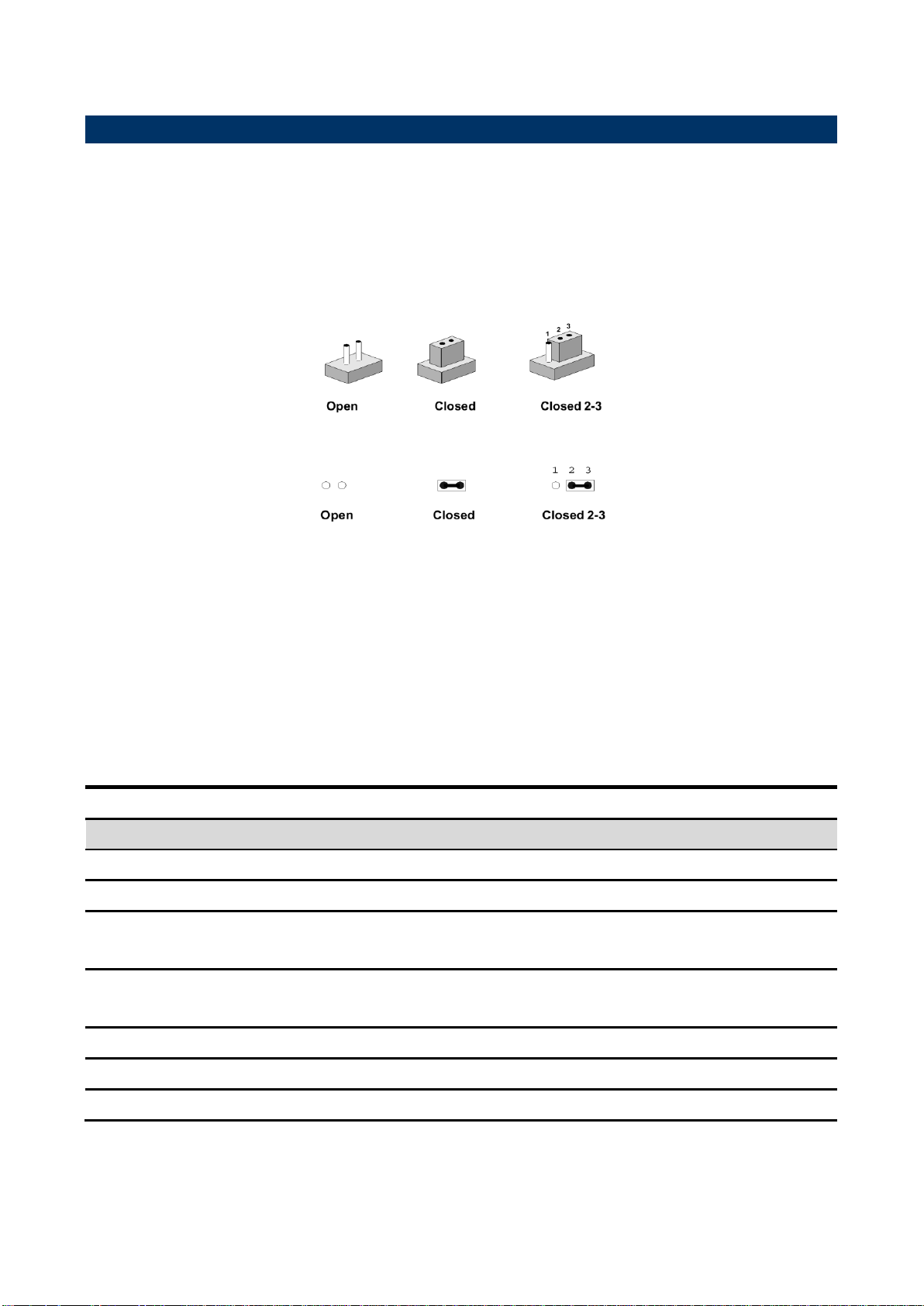
You can configure your board to match the needs of your application by setting jumpers. A
jumper is the simplest kind of electric switch.
It consists of two metal pins and a small metal clip (often protected by a plastic cover) that
slides over the pins to connect them. To “close” a jumper you connect the pins with the clip.
To “open” a jumper you remove the clip. Sometimes a jumper will have three pins, labeled 1,
2, and 3. In this case, you would connect either two pins.
The jumper settings are schematically depicted in this manual as follows:
A pair of needle-nose pliers may be helpful when working with jumpers.
Connectors on the board are linked to external devices such as hard disk drives, a
keyboard, or floppy drives. In addition, the board has a number of jumpers that allow you to
configure your system to suit your application.
If you have any doubts about the best hardware configuration for your application, contact
your local distributor or sales representative before you make any changes.
The following tables list the function of each of the board’s jumpers and connectors.
6 EMX-PNVB Quick Installation Guide
 Loading...