


EMX-H61B
Intel® Core™/ Pentium®/ Celeron® Mini ITX
Motherboard with Intel® H61 Express Chipset
User’s Manual
1st Ed – 15 May 2013
Part No. E2047H61B00R

EMX-H61B User’s Manual
Content
1. Getting Started ............................................................................................................ 4
1.1 Safety Precautions .......................................................................................... 4
1.2 Packing List .................................................................................................... 4
1.3 Document Amendment History ....................................................................... 5
1.4 Manual Objectives .......................................................................................... 6
1.5 Specifications ................................................................................................. 7
1.6 Architecture Overview—Block Diagram.......................................................... 9
2. Hardware Configuration ........................................................................................... 10
2.1 Product Overview ......................................................................................... 11
2.2 Installation Procedure ................................................................................... 13
2.3 Jumper and Connector List .......................................................................... 14
2.4 Setting Jumpers & Connectors ..................................................................... 16
2.4.1 Clear CMOS (JBAT) .............................................................................. 16
2.4.2 ME update (JME) .................................................................................. 16
2.4.3 DDR3/DDR3L using (JDIMM) ............................................................... 17
2.4.4 LVDS connector for 18/24 bit switches (JLVDS) ................................... 17
2.4.5 LVDS Power connector (JLVDS_P) ...................................................... 18
2.4.6 LVDS connector (LVDS1) ..................................................................... 18
2.4.7 General Purpose I/O (JGPIO1) ............................................................. 19
2.4.8 Serial port 1/2 connector (JCOM1/2) ..................................................... 19
2.4.9 System Fan connector (SFAN1) ........................................................... 20
2.4.10 CPU Fan connector (CFAN1) ............................................................... 20
2.4.11 USB Connector 1/2 - USB2.0 (FUSB1/2) ............................................. 21
2.4.12 Front Panel Switches (FPANEL) .......................................................... 21
2.4.13 DC power-in connector (JDCIN) ........................................................... 22
2.4.14 Inverter connector (Inverter) ................................................................. 22
2.4.15 SATA Power connector 1/2 (JSATA_P1/2) .......................................... 23
2.4.16 Speaker Headers (JSPEAK) ................................................................ 23
2.4.17 DC power-in connector (DCIN) ............................................................ 24
3.BIOS Setup .................................................................................................................... 25
3.1 Introduction ................................................................................................... 26
3.2 Starting Setup ............................................................................................... 26
3.3 Using Setup .................................................................................................. 27
3.4 Getting Help ................................................................................................. 28
3.5 In Case of Problems ..................................................................................... 28
3.6 BIOS setup ................................................................................................... 29
2 EMX-H61B User’s Manual

EMX-H61B User’s Manual
3.6.1 Main Menu ............................................................................................ 29
3.6.1.1 System Language .......................................................................... 29
3.6.1.2 System Date .................................................................................. 29
3.6.1.3 System Time .................................................................................. 29
3.6.2 Advanced BIOS settings ....................................................................... 30
3.6.2.1 CPU Configuration ......................................................................... 30
3.6.2.2 Onboard Device Configuration ....................................................... 31
3.6.2.3 USB Legacy Features .................................................................... 32
3.6.2.4 Inter® Rapid Start Technology ....................................................... 33
3.6.2.5 Advanced Power Management ...................................................... 33
3.6.2.6 Super IO Configuration .................................................................. 34
3.6.2.7 HW Monitor .................................................................................... 36
3.6.2.8 Watchdog Configuration ................................................................ 37
3.6.2.9 Serial Port Console Redirection ..................................................... 37
3.6.3 Chipset ..................................................................................................... 39
3.6.3.1 SB Configuration ............................................................................ 39
3.6.3.2 NB Configuration............................................................................ 40
3.6.4 Boot settings ......................................................................................... 41
3.6.5 Security ................................................................................................. 42
3.6.5.1 Administrator Password ................................................................. 42
3.6.5.2 User Password............................................................................... 42
3.6.6 Save & Exit ............................................................................................ 43
3.6.6.1 Save Changes and Reset .............................................................. 43
3.6.6.2 Discard Changes and Reset .......................................................... 43
4. Drivers Installation....................................................................................................... 44
4.1 Install Chipset Driver .................................................................................... 45
4.2 Install VGA Driver ......................................................................................... 46
4.3 Install LAN Driver (For Realtek 8111E Gigabit Ethernet) ............................. 47
4.4 Install ME Driver ........................................................................................... 48
4.5 Install Audio Driver (For Realtek ALC661 HD Audio) ................................... 50
5. Mechanical Drawing .................................................................................................... 51
EMX-H61B User’s Manual 3
EMX-H61B User’s Manual
1. Getting Started
1.1 Safety Precautions
Warning!
Always completely disconnect the power cord from your
chassis whenever you work with the hardware. Do not
make connections while the power is on. Sensitive
electronic components can be damaged by sudden power
surges. Only experienced electronics personnel should
open the PC chassis.
Caution!
Always ground yourself to remove any static charge before
touching the CPU card. Modern electronic devices are very
sensitive to static electric charges. As a safety precaution,
use a grounding wrist strap at all times. Place all electronic
components in a static-dissipative surface or static-shielded
bag when they are not in the chassis.
Always note that improper disassembling action could cause damage to the
motherboard. We suggest not removing the heatsink without correct
instructions in any circumstance. If you really have to do this, please contact
us for further support.
1.2 Packing List
Before you begin installing your single board, please make sure that the
following materials have been shipped:
Quick Installation Guide X 1
Driver/Utility CD X 1
Serial ATA Signal Cable X 1
Serial ATA Power Cable X 1
IO Shield
COM Cable X 1
Screw X 2
CPU Cooler back plate
Motherboard X 1
4 EMX-H61B User’s Manual

EMX-H61B User’s Manual
Revision
Date
By
Comment
1st
May 2013
Avalue
Initial Release
1.3 Document Amendment History
EMX-H61B User’s Manual 5

EMX-H61B User’s Manual
1.4 Manual Objectives
This manual describes in details Avalue Technology EMX-H61B Single Board.
We have tried to include as much information as possible but we have not duplicated
information that is provided in the standard IBM Technical References, unless it proved to
be necessary to aid in the understanding of this board.
We strongly recommend that you study this manual carefully before attempting to set up
EMX-H61B series or change the standard configurations. Whilst all the necessary
information is available in this manual we would recommend that unless you are confident,
you contact your supplier for guidance.
If you have any suggestions or find any errors regarding this manual and want to inform us
of these, please contact our Customer Service department with the relevant details.
6 EMX-H61B User’s Manual
EMX-H61B User’s Manual
System
CPU
Intel® LGA1155 Socket Supports 2nd /3rd Generation Core™ i7/ i5/ i3,
Pentium® and Celeron® Processors (Max. TDP at 65W)
BIOS
AMI uEFI BIOS, 64Mbit SPI Flash ROM
System Chipset
Intel® H61 Chipset
I/O Chip
ITE IT8728F
System Memory
2 x 204-pin DDR3/DDR3L(Jumper Selectable) 1333/1600 SODIMMs, Up to 16
GB
Watchdog Timer
H/W Reset, 1sec. – 65535sec./min.
1sec. or 1min. step
H/W Status
Monitor
CPU & system temperature monitoring
Voltages monitoring
TPM
N/A
Buzzer
Buzzer onboard
Expansion
1 x Mini PCI-e supported mSATA
1 x Mini PCI-e supported WiFi
I/O
Rear Side External
I/O Connector
1 x RJ-45
2 x dual deck USB 2.0 connectors
1 x VGA
1 x HDMI
1 x Mic-In and 1 x Line-out
DC Jack
Internal I/O
Connector
Storage:
- 2 x SATA II connectors
- 2 x SATA power connectors
- 1 x mSATA by Mini PCI-e slot
COM:
- COM1~2: support RS-232 connector, without / +5V&+12V supported
GPIO: 8 bits
1 x Mini PCI-e slot for WiFi
2 x 2 x 5 pin, pitch 2.54mm connector for USB 2.0
1 x 4 pin CPU fan connector with smart fan function supported
1 x 3 pin System fan connector.
1 x horizontal type battery connector
1 x 2 x 5 pin, pitch 2.54mm connector for front panel
1.5 Specifications
EMX-H61B User’s Manual 7
EMX-H61B User’s Manual
1 x 2 x 2 pin ATX power connector for DC +12~19V input
1 x 2 x 15 pin , pitch 1.00mm connector for LVDS
1 x 6 pin , pitch 2.00mm connector for Inverter
1 x 4 pin , pitch 2.00mm connector for speaker
1 x DC Jack connector
Display
Chipset
Intel H61 integrated
Resolution
Dual display pipes supported
- HDMI: 1920x1080
- VGA: 2048x1536
LVDS
Pardac PS8625 eDP to LVDS ,Support 2CH 24bits LVDS 1920x1200
Audio
Chipset
Realtek ALC661 HD Audio Decoding Controller.
Audio Interface
Mic-In, Line-In
Audio Amplifier
Realtek ALC112 Stereo Class-D 5W x 2
Ethernet
Chipset
1 x Realtek RTL8111E PCI-Express Gigabit Ethernet
Ethernet Interface
10/100/1000 Gigabit Ethernet
Mechanical &
Environmental
Power
Requirement
DC in +12V~19V
Power Type
Single power +12V~19V Power input / ATX mode
ACPI
Single power ATX Support S0,S1, S3, S4, S5
ACPI 3.0 Compliant
Operating Temp.
0°C ~60°C
Storage Temp.
-40°C ~75°C
Operating
Humidity
0%~90% relative humidity, non-condensing
Size (L x W)
6.7" x 6.7" (170mm x 170mm)
Weight
0.40 kg
8 EMX-H61B User’s Manual
EMX-H61B User’s Manual
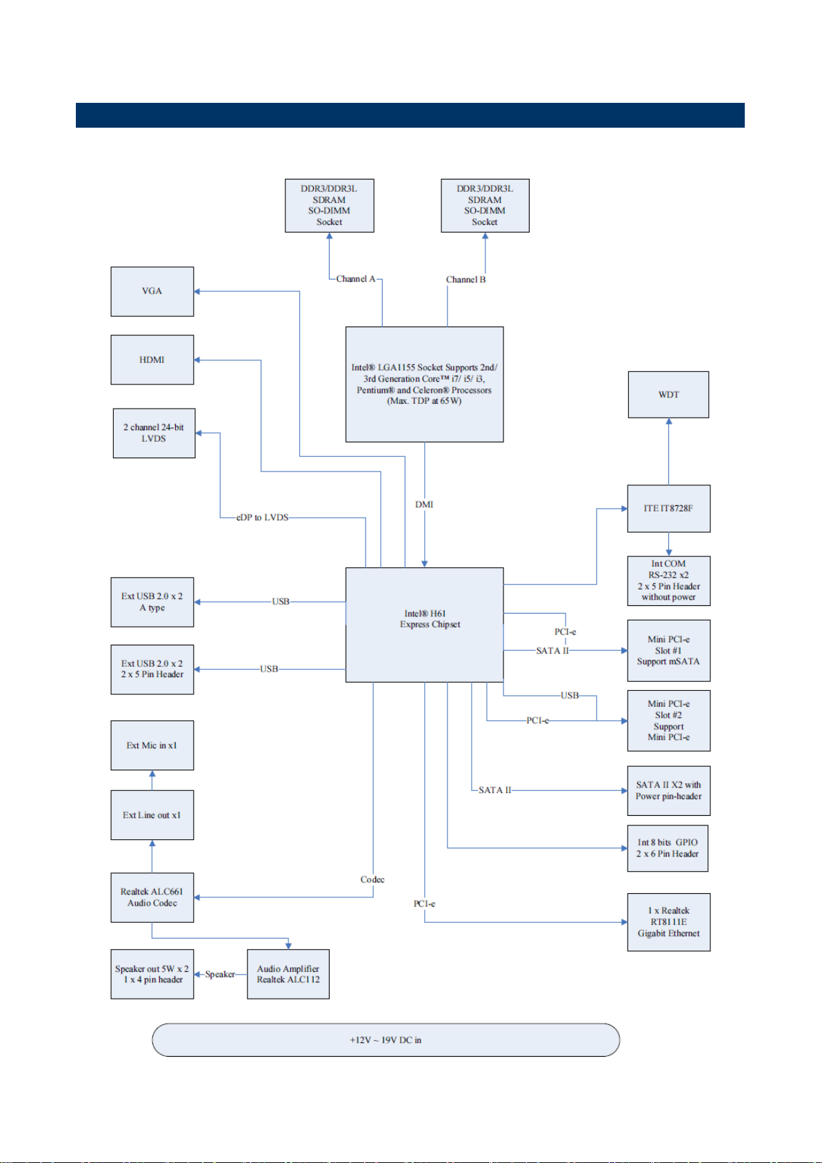
1.6 Architecture Overview—Block Diagram
The following block diagram shows the architecture and main components of EMX-H61B.
EMX-H61B User’s Manual 9

EMX-H61B User’s Manual
2. Hardware
Configuration
10 EMX-H61B User’s Manual
EMX-H61B User’s Manual
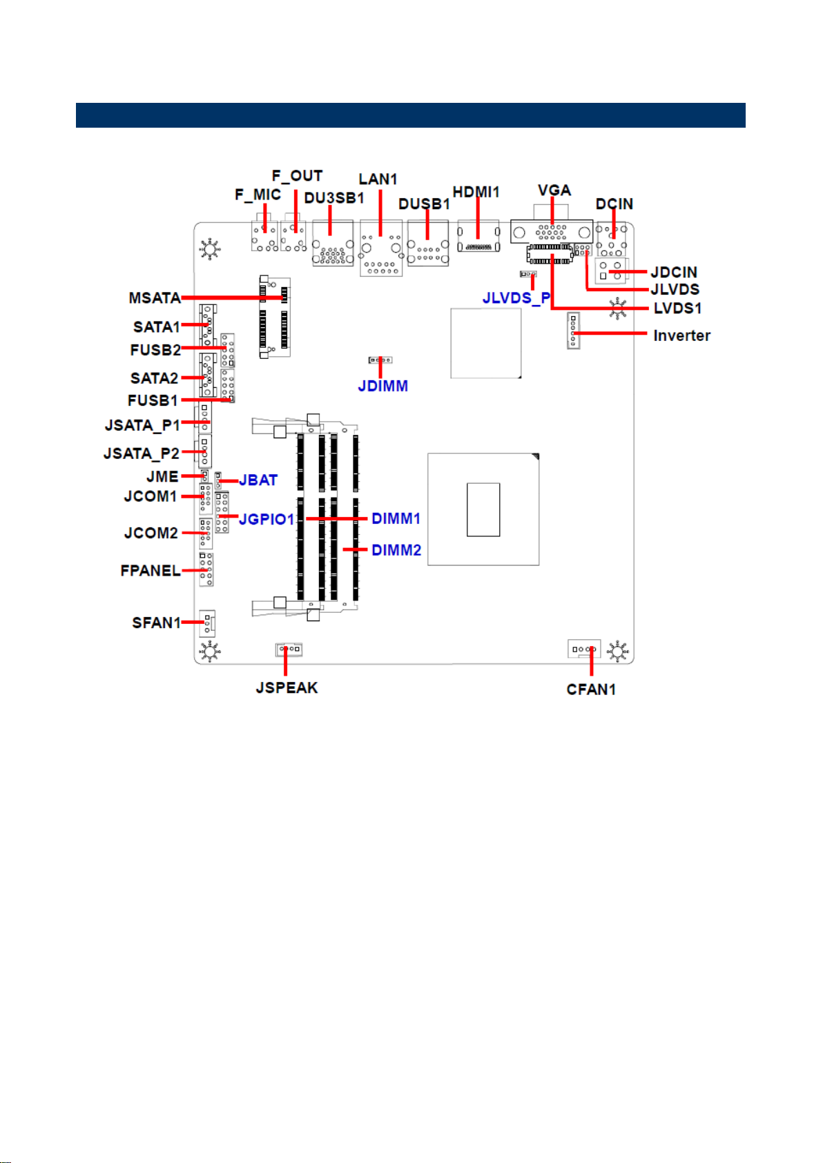
2.1 Product Overview
EMX-H61B User’s Manual 11
EMX-H61B User’s Manual
12 EMX-H61B User’s Manual

EMX-H61B User’s Manual
2.2 Installation Procedure
This chapter explains you the instructions of how to setup your system.
1. Turn off the power supply.
2. Insert the DIMM module (be careful with the orientation).
3. Insert all external cables for hard disk, floppy, keyboard, mouse, USB etc. except for flat
panel. A CRT monitor must be connected in order to change BIOS settings to support flat
panel.
4. Connect power supply to the board via the AC/DC Adapter.
5. Turn on the power.
6. Enter the BIOS setup by pressing the delete key during boot up. Use the "Save & Exit \
Restore Defaults" feature.
7. If TFT panel display is to be utilized, make sure the panel voltage is correctly set before
connecting the display cable and turning on the power.
EMX-H61B User’s Manual 13
EMX-H61B User’s Manual
Jumpers
Label
Function
Note
JBAT
Clear CMOS
1 x 3 header, pitch 2.00 mm
JME
ME update
1 x 2 header, pitch 2.00 mm
JLVDS
LVDS connector for 18/24 bit switches
2 x 3 header, pitch 2.00 mm
JLVDS_P
LVDS Power connector
1 x 3 header, pitch 2.00 mm
JDIMM
DDR3/DDR3L using
1 x 4 header, pitch 2.00 mm
Connectors
Label
Function
Note
F_MIC
Mic-in audio jack
3.5mm phone jack
F_OUT
Line-out audio jack
3.5mm phone jack
DU3SB1
USB connector
Stack USB 2.00 connector
2.3 Jumper and Connector List
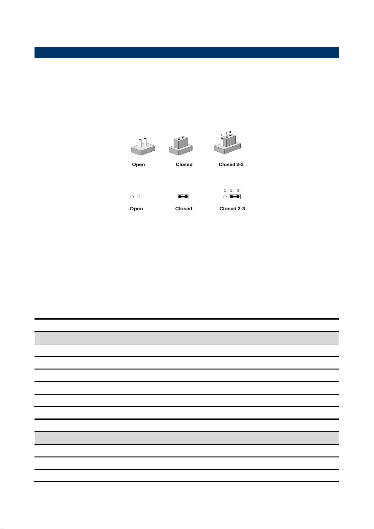
You can configure your board to match the needs of your application by setting jumpers. A
jumper is the simplest kind of electric switch.
It consists of two metal pins and a small metal clip (often protected by a plastic cover) that
slides over the pins to connect them. To “close” a jumper you connect the pins with the clip.
To “open” a jumper you remove the clip. Sometimes a jumper will have three pins, labeled 1,
2, and 3. In this case, you would connect either two pins.
The jumper settings are schematically depicted in this manual as follows:
A pair of needle-nose pliers may be helpful when working with jumpers.
Connectors on the board are linked to external devices such as hard disk drives, a
keyboard, or floppy drives. In addition, the board has a number of jumpers that allow you to
configure your system to suit your application.
If you have any doubts about the best hardware configuration for your application, contact
your local distributor or sales representative before you make any changes.
The following tables list the function of each of the board’s jumpers and connectors.
14 EMX-H61B User’s Manual

EMX-H61B User’s Manual
DUSB1
USB connector
Stack USB 2.00connector
LAN1
RJ-45 Ethernet connector 1
RJ45 w/ indicator connector
DCIN
DC power-in connector
JDCIN
DC power-in connector
2 x 2 wafer , pitch 4.20 mm
FPANEL
Front Panel Switches
2 x 5 header, pitch 2.54 mm
LVDS1
LVDS connector
2 x15 wafer, pitch 1.0 mm
JSPEAK
Speaker Headers
1 x 4 wafer, pitch 2.00 mm
HDMI1
HDMI connector
MSATA
mSATA slot
Full size
SATA1/2
Serial ATA connector 1/2
SATA 7P connector
JSATA_P1/2
SATA Power connector 1/2
1 x 4 wafer, pitch 2.54 mm
JCOM1/2
Serial port 1/2 connector
2 x 5 header, pitch 2.00 mm
JGPIO1
General Purpose I/O
2 x 6 header, pitch 2.54 mm
F_USB1/2
USB Connector 1/2 - USB2.0
2 x 5 header, pitch 2.54 mm
SFAN1
System Fan connector
1 x 3 wafer, pitch 2.54 mm
CFAN1
CPU Fan connector
1 x 4 wafer, pitch 2.54 mm
VGA
VGA connector
D-SUB 15pin
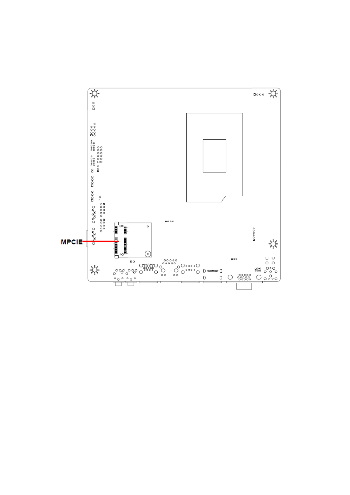
MPCIE
Mini-PCIe
Half size
DIMM1
DDR3 SODIMM connector1
SO-DIMM 204Pin
DIMM2
DDR3 SODIMM connector2
SO-DIMM 204Pin
Inverter
Inverter connector
1 x 6 wafer, pitch 2.00mm
EMX-H61B User’s Manual 15
EMX-H61B User’s Manual
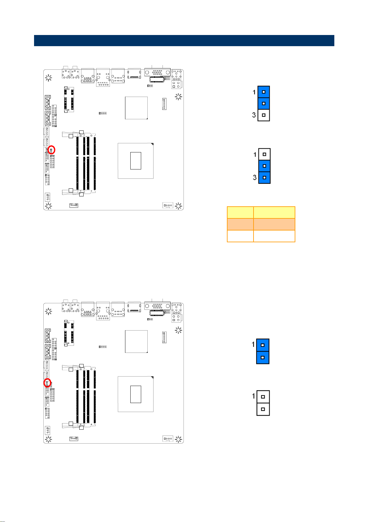
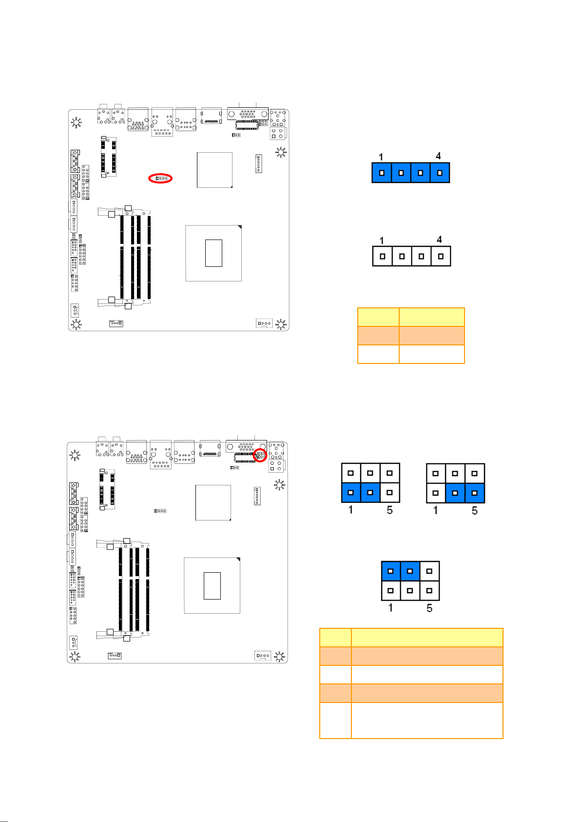
* Default
Normal*
Clear CMOS
Pin
Define
1-2
Normal
2-3
Clear CMOS
* Default
Refresh the ME*
Can’t refresh the ME
2.4 Setting Jumpers & Connectors
2.4.1 Clear CMOS (JBAT)
2.4.2 ME update (JME)
16 EMX-H61B User’s Manual
EMX-H61B User’s Manual
* Default
DDR3*
DDR3L
Pin
Define
Open
DDR3L
Close
DDR3
* Default
8 BIT JEIDE* 8BIT VESA
SINGLE LINK LVDS
Pin
Define
1-3
8BIT JEIDE
3-5
8BIT VESA
NC
6BIT
2-4
NC=DUANL LINK LVDS
CLOS=SINGLE LINK LVDS
2.4.3 DDR3/DDR3L using (JDIMM)
2.4.4 LVDS connector for 18/24 bit switches (JLVDS)
EMX-H61B User’s Manual 17

EMX-H61B User’s Manual
* Default
+5V*
+3.3V
Pin
Define
Max current
1-2
+3.3V
1A
2-3
+5V
1A
Note: This jumper is working for LVDS1 VDD
power.
Note: Mapping connector CSI-1171-30 (1.0mm).
Signal
PIN
PIN
Signal
GND
1 2 GND
DTX0+
3 4 DTX1+
DTX0-
5 6 DTX1-
DTX2+
7 8 DCLK+
DTX2-
9
10
DCLK-
DTX3+
11
12
GND
DTX3-
13
14
TX3+
GND
15
16
TX3-
TX0+
17
18
TX1+
TX0-
19
20
TX1-
TX2+
21
22
CLK+
TX2-
23
24
CLK-
GND
25
26
GND
VDD
27
28
VDD
VDD
29
30
VDD
2.4.5 LVDS Power connector (JLVDS_P)
2.4.6 LVDS connector (LVDS1)
18 EMX-H61B User’s Manual

EMX-H61B User’s Manual
Signal
PIN
PIN
Signal
+5V
1 2 12V
GPO
3 4 GPI
GPO
5 6 GPI
GPO
7 8 GPI
GPO
9
10
GPI
GND
11
12
GND
Signal
PIN
PIN
Signal
DCD
1 2 RXD
TXD
3 4 RTD
GND
5 6 DSR
RTS
7 8 CTS
RI
9
Note: COM 1/2 Pin9 without power.
JCOM2
JCOM1
2.4.7 General Purpose I/O (JGPIO1)
2.4.8 Serial port 1/2 connector (JCOM1/2)
EMX-H61B User’s Manual 19

EMX-H61B User’s Manual
PIN
Signal
1
RPM
2
+12V
3
Ground
PIN
Signal
1
Ground
2
+12V
3
RPM
4
Control
2.4.9 System Fan connector (SFAN1)
2.4.10 CPU Fan connector (CFAN1)
20 EMX-H61B User’s Manual

EMX-H61B User’s Manual
Signal
PIN
PIN
Signal
GND
10
GND
8 7 GND
DATA+
6 5 DATA+
DATA-
4 3 DATA-
5V
2 1 5V
Signal
PIN
PIN
Signal
HDLED+
1 2 PWRLED+
HDLED-
3 4 PWRLED-
GND
5 6 GND
RESET
7 8 PWRBTN#
10
GND
FUSB1
FUSB2
2.4.11 USB Connector 1/2 - USB2.0 (FUSB1/2)
2.4.12 Front Panel Switches (FPANEL)
EMX-H61B User’s Manual 21

EMX-H61B User’s Manual
Signal
PIN
PIN
Signal
GND
2 4 +12~19V
GND
1 3 +12~19V
Note: Suggest bundle with 19V power adapter.
PIN
Signal
Max current
1
+12V
1A 2 +12V
1A
3
BLK_ON
4
Brightness
5 GND
6 GND
Note: Mapping connector PHR6.
2.4.13 DC power-in connector (JDCIN)
2.4.14 Inverter connector (Inverter)
22 EMX-H61B User’s Manual

EMX-H61B User’s Manual
PIN
Signal
Max current
1
+12V
1A 2 GND
3 GND
4 VCC
PIN
Signal
1
INTSPL+
2
INTSPL-
3
INTSPR+
4
INTSPR-
Note: Support 5W 8ΩX 2 speaker.
Mapping connector PHR-4.
JSATA_P2
JSATA_P1
2.4.15 SATA Power connector 1/2 (JSATA_P1/2)
2.4.16 Speaker Headers (JSPEAK)
EMX-H61B User’s Manual 23

EMX-H61B User’s Manual
2.4.17 DC power-in connector (DCIN)
24 EMX-H61B User’s Manual

EMX-H61B User’s Manual
3.BIOS Setup
EMX-H61B User’s Manual 25

EMX-H61B User’s Manual
3.1 Introduction
The BIOS setup program allows users to modify the basic system configuration. In this
following chapter will describe how to access the BIOS setup program and the
configuration options that may be changed.
3.2 Starting Setup
The BIOS is immediately activated when you first power on the computer. The BIOS reads
the system information contained in the NVRAM and begins the process of checking out
the system and configuring it. When it finishes, the BIOS will seek an operating system on
one of the disks and then launch and turn control over to the operating system.
While the BIOS is in control, the Setup program can be activated in one of two ways:
By pressing <Del> immediately after switching the system on, or
By pressing the <Del> key when the following message appears briefly at the bottom of the
screen during the POST (Power On Self Test).
Press DEL to enter setup, F11 to popup menu
If the message disappears before you respond and you still wish to enter Setup, restart the
system to try again by turning it OFF then ON or pressing the "RESET" button on the
system case. You may also restart by simultaneously pressing <Ctrl>, <Alt>, and <Delete>
keys. If you do not press the keys at the correct time and the system does not boot, an error
message will be displayed and you will again be asked to.
Press DEL to enter setup, F11 to popup menu
26 EMX-H61B User’s Manual

EMX-H61B User’s Manual
Button
Description
↑
Move to previous item
↓
Move to next item
←
Move to the item in the left hand
→
Move to the item in the right hand
Esc key
Main Menu -- Quit and not save changes into NVRAM
Status Page Setup Menu and Option Page Setup Menu -- Exit current page and
return to the pervious page or Main Menu
+ key
Increase the numeric value or make changes
- key
Decrease the numeric value or make changes
F1 key
General help, only for Status Page Setup Menu and Option Page Setup Menu
F7 key
Previous Values
F9 key
Optimized Defaults
F10 key
Save and Exit
3.3 Using Setup
In general, you use the arrow keys to highlight items, press <Enter> to select, use the
PageUp and PageDown keys to change entries, press <F1> for help and press <Esc> to
quit. The following table provides more detail about how to navigate in the Setup program
using the keyboard.
Navigating Through The Menu Bar
Use the left and right arrow keys to choose the menu you want to be in.
Note: Some of the navigation keys differ from one screen to another.
To Display a Sub Menu
Use the arrow keys to move the cursor to the sub menu you want. Then press
<Enter>. A “” pointer marks all sub menus.
EMX-H61B User’s Manual 27

EMX-H61B User’s Manual
3.4 Getting Help
Press F1 to pop up a small help window that describes the appropriate keys to use and the
possible selections for the highlighted item. To exit the Help Window press <Esc> or the F1
key again.
3.5 In Case of Problems
If, after making and saving system changes with Setup, you discover that your computer no
longer is able to boot, the BIOS supports an override to the NVRAM settings which resets
your system to its defaults.
The best advice is to only alter settings which you thoroughly understand. To this end, we
strongly recommend that you avoid making any changes to the chipset defaults. These
defaults have been carefully chosen by both AMI and your systems manufacturer to
provide the absolute maximum performance and reliability. Even a seemingly small change
to the chipset setup has the potential for causing you to use the override.
28 EMX-H61B User’s Manual

EMX-H61B User’s Manual
3.6 BIOS setup
Once you enter the BIOS Setup Utility, the Main Menu will appear on the screen. The Main
Menu allows you to select from several setup functions and exit choices. Use the arrow
keys to select among the items and press <Enter> to accept and enter the sub-menu.
3.6.1 Main Menu
This section allows you to record some basic hardware configurations in your computer and
set the system clock.
3.6.1.1 System Language
Use this option to select system language
3.6.1.2 System Date
Use the system date option to set the system date. Manually enter the day, month and
year.
3.6.1.3 System Time
Use the system time option to set the system time. Manually enter the hours, minutes and
seconds.
Note: BIOS setup screens shown in this chapter are for reference only, and may
not exactly match what you see on your screen. Visit the Avalue website
(www.avalue.com.tw) to download the latest product and BIOS information.
EMX-H61B User’s Manual 29

EMX-H61B User’s Manual
3.6.2 Advanced BIOS settings
This section allows you to configure your CPU and other system devices for basic operation
through the following sub-menus.
3.6.2.1 CPU Configuration
Use the CPU configuration menu to view detailed CPU specification and configure the
CPU.
30 EMX-H61B User’s Manual

EMX-H61B User’s Manual
Item
Options
Description
Onboard LAN1 Control
Disabled
Enabled[Default]
Enable or disable Onboard LAN1.
Mini PCIE Control
Disabled
Enabled[Default]
Enable or disable Mini PCIE.
Launch PXE OpROM policy
Disabled[Default]
Enabled
Controls the execution of UEFI and Legacy
PXE OpROM.
Launch Storage OpROM policy
Disabled
Enabled[Default]
Controls the execution of UEFI and Legacy
Storage OpROM.
USB Control
Disabled
Enabled[Default]
Enable/Disable USB controller.
Onboard Audio Control
Disabled
Enabled
Auto[Default]
Control Detection of the Azalia device.
Disabled = Azalia will be unconditionally
disabled Enabled = Azalia will be
unconditionally enabled Auto = Azalia will be
enabled if present, disabled otherwise.
Intel HDMI codec Port C
Disabled
Enabled[Default]
Enable or disable internal HDMI codec Port for
Azalia.
3.6.2.2 Onboard Device Configuration
EMX-H61B User’s Manual 31

EMX-H61B User’s Manual
Item
Options
Description
Legacy USB Support
Enabled[Default]
Disabled
Auto
Enables Legacy USB support, AUTO option
disables legacy support if no USB devices are
connected. DISABLE option will keep USB
devices available only for EFI applications.
EHCI Hand-off
Disabled[Default]
Enabled
This is a workaround for OSes without EHCI
hand-off support. The EHCI ownership change
should be claimed by EHCI driver.
Port 60/64 Emulation
Disabled
Enabled[Default]
Enables I/O port 60h/64h emulation support.
This should be enabled for the complete USB
keyboard legacy support for non-USB aware
OSes.
USB transfer time-out
1 sec
5 sec
10 sec
20 sec[Default]
The time-out value for Control, Bulk, and
Interrupt transfers.
Device reset time-out
10 sec
20 sec[Default]
30 sec
40 sec
USB mass storage device Start Unit command
time-out.
Device power-up delay
Auto[Default]
Manual
Maximum time the device will take before it
properly reports itself to the Host Controller.
‘Auto’ uses default value: for a Root port it is
100 ms, for a Hub port the delay is taken from
Hub descriptor.
SanDisk Extreme 0001
Auto[Default]
Floppy
Forced FDD
Hard Disk
CD-ROM
Mass storage device emulation type. ‘AUTO’
enumerates devices according to their media
format. Optical drives are emulated as
‘CDROM’, drives with no media will be
emulated according to a drive type.
3.6.2.3 USB Legacy Features
32 EMX-H61B User’s Manual

EMX-H61B User’s Manual
Item
Options
Description
ACPI Sleep State
Suspend Disabled
S1 only(CPU Stop Clock)[Default]
S3 only(Suspend to RAM)
Select ACPI sleep state the system will enter
when the SUSPEND button is pressed.
3.6.2.4 Inter® Rapid Start Technology
3.6.2.5 Advanced Power Management
EMX-H61B User’s Manual 33

EMX-H61B User’s Manual
Wake on LAN
Disabled[Default]
Enabled
Enable system to wake from S5 using LAN
wake event.
Power-Loss State
Power Off[Default]
Power On
Keep Last State
Specify what state to go to when power is
re-applied after a power failure.
Poweron By RTC
Disabled[Default]
Enabled
Enable or disable System wake on alarm
event. When enabled, System will wake on the
hr::min::sec specified.
Item
Description
Serial Port 0 Configuration
Set Parameters of Serial Port 0 (COMA).
Serial Port 1 Configuration
Set Parameters of Serial Port 1 (COMB).
3.6.2.6 Super IO Configuration
You can use this item to set up or change the Super IO configuration for FDD controllers,
parallel ports and serial ports.
34 EMX-H61B User’s Manual

EMX-H61B User’s Manual
Item
Option
Description
Serial Port
Disabled
Enabled[Default]
Enable or Disable Serial Port
(COM).
Change Settings
Auto[Default]
IO=3F8h; IRQ=4;
IO=3F8h; IRQ=3,4,5,6,7,9,10,11,12;
IO=2F8h; IRQ=3,4,5,6,7,9,10,11,12;
IO=3E8h; IRQ=3,4,5,6,7,9,10,11,12;
IO=2E8h; IRQ=3,4,5,6,7,9,10,11,12;
Select an optimal setting for
Super IO device.
3.6.2.6.1 Serial Port 0 Configuration
3.6.2.6.2 Serial Port 1 Configuration
EMX-H61B User’s Manual 35

EMX-H61B User’s Manual
Item
Option
Description
Serial Port
Disabled
Enabled[Default]
Enable or Disable Serial Port
(COM).
Change Settings
Auto[Default]
IO=2F8h; IRQ=3;
IO=3F8h; IRQ=3,4,5,6,7,9,10,11,12;
IO=2F8h; IRQ=3,4,5,6,7,9,10,11,12;
IO=3E8h; IRQ=3,4,5,6,7,9,10,11,12;
IO=2E8h; IRQ=3,4,5,6,7,9,10,11,12;
Select an optimal setting for
Super IO device.
Item
Options
Description
Smart Fan 1 Mode
Full on Mode
Automatic Mode[Default]
Smart Fan 1 Mode Select.
Fan off temperature limit
0-127
Fan will off when temperature lower than this
limit. [0-127]
Fan start temperature limit
0-127
Fan will work when temperature higher than
this limit. [0-127]
Fan start PWM
0-255
Fan will stat with this PWM value. [0-255]
PWM SLOPE SETTING
0-127
PWM SLOPE Value. [0-127]
3.6.2.7 HW Monitor
The H/W Monitor shows the operating temperature, fan speeds and system voltages.
36 EMX-H61B User’s Manual

EMX-H61B User’s Manual
Item
Options
Description
Watchdog Count Mode
Second[Default]
Minute
Watchdog Count Mode Selection.
Watchdog TimeOut Value
0 to 255
Set Watchdog time, from 0 to 255.
3.6.2.8 Watchdog Configuration
3.6.2.9 Serial Port Console Redirection
EMX-H61B User’s Manual 37

EMX-H61B User’s Manual
Item
Options
Description
Console Redirection
Disabled
Enabled[Default]
Console Redirection Enable or Disable.
Console Redirection Settings
The settings specify how the host computer and the remote computer
(which the user is using) will exchange data. Both computers should have
the same or compatible settings.
Item
Options
Description
Out-of-Band Mgmt Port
COM0[Default]
Microsoft Windows Emergency Management.
Services (EMS) allows for remote management of a
Windows Server OS through a serial port.
Terminal Type
VT100
VT100+
VT-UTF8[Default]
ANSI
VT-UTF8 is the preferred terminal type for
out-of-band management. The next best choice is
VT100+ and then VT100. See above, in Console
Redirection Settings page, for more Help with
Terminal Type/Emulation.
Bits per second
9600
19200
57600
115200[Default]
Select serial port transmission speed. The speed
must be matched on the other side. Long or noisy
lines may require lower speeds.
Flow Control
None[Default]
Hardware RTS/CTS
Software Xon/Xoff
Flow control can prevent data loss from buffer
overflow. When sending data, if the receiving buffers
are full, a ‘stop’ signal can be sent to stop the data
flow. Once the buffers are empty, a ‘start’ signal can
be sent to re-start the flow. Hardware flow control
uses two wires to send start/stop signals.
3.6.2.9.1 Console Redirection Settings
38 EMX-H61B User’s Manual

EMX-H61B User’s Manual
Item
Description
SB Configuration
PCH Parameters.
NB Configuration
NB Parameters.
3.6.3 Chipset
3.6.3.1 SB Configuration
EMX-H61B User’s Manual 39

EMX-H61B User’s Manual
Item
Options
Description
SATA Mode Selection
IDE[Default]
AHCI
Determines how SATA controller(s) operate.
IDE Legacy / Native Mode
Selection
Native[Default]
Legacy
IDE Legacy / Native Mode Selection.
Item
Options
Description
DVMT Pre-Allocated
32M/64M[Default]/96M/128M/
160M/192M/224M/256M/288M
/320M/352M/384M/416M/448
M/480M/512M/1024M
Select DVMT 5.0 Pre-Allocated (Fixed)
Graphics Memory size used by the Internal
Graphics Device.
DVMT Total Gfx Mem
128M/256M[Default]/MAX
Select DVMT 5.0 Total Graphics Memory size
used by the Internal Graphics Device.
Primary IGFX Boot Display
VBIOS Default[Default]
CRT
None Use
LVDS
None Use
HDMI
None Use
Select the Video Device which will be
activated during POST. This has no effect if
external graphics present. Secondary boot
display selection will appear based on your
selection. VGA modes will be supported only
on primary display.
Active LFP
No LVDS[Default]
eDP Port-D
Select the Active LFP Configuration. No
LVDS:VBIOS does not enable LVDS. eDP
Port-D:LFP Driven by Int-DisplayPort encoder
from Port-D(through PCH).
LCD Panel Type
VBIOS Default[Default]
640x480 18/1
800x600 18/1
1024x768 18/1
1280x1024 24/2
1400x1050 24/1
Select LCD panel used by Internal Graphics
Device by selecting the appropriate setup
item. (VBIOS Default: 1024x768)
3.6.3.2 NB Configuration
40 EMX-H61B User’s Manual

EMX-H61B User’s Manual
1400x1050 24/2
1600x1200 24/2
1366x768 24/1
1680x1050 24/2
1920x1200 24/2
1440x900 18/2
1600x900 24/2
1024x768 24/1
1280x800 18/1
1920x1080 24/2
2048x1536 24/2
Backlight Control
PWM Inverted[Default]
PWM Normal
Back Light Control Setting.
Item
Option
Description
Setup Prompt Timeout
1~65535
Number of seconds to wait for
setup activation key.
65535(0xFFFF) means indefinite
waiting.
Bootup NumLock State
On[Default]
Off
Select the keyboard NumLock
state.
Full Logo Screen
Disabled[Default]
Enabled
Enables or disables Full Logo
Screen option.
Fast Boot
Disabled[Default]
Enabled
Enables or disables boot with
initialization of a minimal set of
devices required to launch active
boot option. Has no effect for BBS
boot options.
Boot Option #1
Sets the system boot order.
3.6.4 Boot settings
EMX-H61B User’s Manual 41

EMX-H61B User’s Manual
3.6.5 Security
Use the Security menu to set system and user password.
3.6.5.1 Administrator Password
This setting specifies a password that must be entered to access the BIOS Setup Utility. If
only the Administrator's password is set, then this only limits access to the BIOS setup
program and is only asked for when entering the BIOS setup program. By default, no
password is specified.
3.6.5.2 User Password
This setting specifies a password that must be entered to access the BIOS Setup Utility or
to boot the system. If only the User's password is set, then this is a power on password and
must be entered to boot or enter the BIOS setup program. In the BIOS setup program, the
User will have Administrator rights. By default, no password is specified.
42 EMX-H61B User’s Manual

EMX-H61B User’s Manual
3.6.6 Save & Exit
3.6.6.1 Save Changes and Reset
Any changes made to BIOS settings are stored in NVRAM. The setup program then exits
and reboots the controller.
3.6.6.2 Discard Changes and Reset
Any changes made to BIOS settings during this session of the BIOS setup program are
discarded. The setup program then exits and reboots the controller.
EMX-H61B User’s Manual 43

EMX-H61B User’s Manual
4. Drivers Installation
Note: Installation procedures and screen shots in this section are
for your reference and may not be exactly the same as
shown on your screen.
44 EMX-H61B User’s Manual

EMX-H61B User’s Manual
Insert the Supporting DVD-ROM to
DVD-ROM drive, click on “start” icon and it
should show the index page of Avalue’s
products automatically. If not, locate the
folder HTML and choose the product from
the targeted folder.
Note: The installation procedures and
screen shots in this section are based
on Windows 7 operating system.
Step 1. Locate
「\Driver_Chipset\Intel\EMX-H61B_Chipset」.
Step 4. Select Next to continue
installation.
Step 2. Select Next to start setup.
Step 5. Select Next to continue
installation.Select Finish to complete
Installation.
Step 3. Select Yes to the next step.
Step 6. Select Finish to complete
Installation.
4.1 Install Chipset Driver
EMX-H61B User’s Manual 45

EMX-H61B User’s Manual
Insert the Supporting DVD-ROM to
DVD-ROM drive, click on “start” icon and it
should show the index page of Avalue’s
products automatically. If not, locate the
folder HTML and choose the product from
the targeted folder.
Note: The installation procedures and
screen shots in this section are
based on Windows 7 operating
system.
Step 1. Locate 「\VGA\EMX-H61B_VGA」.
Step 4. Select Next to continue
installation.
Step 2. Select Next to start setup.
Step 5. Select Next to continue installation.
Step 3. Select Yes to the next step.
Step 6. Select Finish to complete
installation.
4.2 Install VGA Driver
46 EMX-H61B User’s Manual

EMX-H61B User’s Manual
Insert the Supporting DVD-ROM to DVD-ROM
drive, and it should show the index page of
Avalue’s products automatically. If not, locate
Index.htm and choose the product from the
menu left, or link to
\Driver_Gigabit\Realtek\RTL8111E\EMX-H61B
_LAN.
Note: The installation procedures and screen
shots in this section are based on
Windows 7 operation system.
Step 3. Click Finish to complete setup.
Step 1. Click Next to Install.
Step 2. Click Install to begin the installation.
4.3 Install LAN Driver (For Realtek 8111E Gigabit Ethernet)
EMX-H61B User’s Manual 47

EMX-H61B User’s Manual
Insert the Supporting DVD-ROM to
DVD-ROM drive, click on “start” icon and it
should show the index page of Avalue’s
products automatically. If not, locate the
folder HTML and choose the product from
the targeted folder.
Note: The installation procedures and
screen shots in this section are
based on Windows 7 operating
system.
Step 1. Locate
「\Utility\EMX-H61B_ME_5M_Driver_Production」.
Step 4. Select Next to continue
installation.
Step 2. Select Next to start setup.
Step 5. Select Install to continue
installation.
Step 3. Select Yes to the next step.
Step 6. Select Next to continue
installation.
4.4 Install ME Driver
48 EMX-H61B User’s Manual

EMX-H61B User’s Manual
Step 7. Select Finish to complete installation
EMX-H61B User’s Manual 49

EMX-H61B User’s Manual
Insert the Supporting DVD-ROM to
DVD-ROM drive, and it should show the
index page of Avalue’s products
automatically. If not, locate Index.htm and
choose the product from the menu left, or
link to
\Driver_Audio\EMX-H61B_Audio\R2.66
Note: The installation procedures and
screen shots in this section are
based on Windows 7 operation
system. If the warning message
appears while the installation
process, click Continue to go on.
Step1. Click Next to Install..
Step 2. Select Finish to complete
Installation.
4.5 Install Audio Driver (For Realtek ALC661 HD Audio)
50 EMX-H61B User’s Manual

EMX-H61B User’s Manual
5. Mechanical Drawing
EMX-H61B User’s Manual 51

EMX-H61B User’s Manual
Unit: mm
52 EMX-H61B User’s Manual

EMX-H61B User’s Manual
Unit: mm
EMX-H61B User’s Manual 53

EMX-H61B User’s Manual
Unit: mm
54 EMX-H61B User’s Manual
 Loading...