


EMX-CDT
Intel® Atom™ Cedar Trail Mini ITX Motherboard
With Intel® D2550 Processor + NM10 Chipset
Quick Installation Guide
2nd Ed – 6 July 2012
Copyright Notice
Copyright 2011-2012 Avalue Technology Inc., ALL RIGHTS RESERVED.
Part No. E2017XCDT01R

EMX-CDT Quick Installation Guide
Content
1. Getting Started ............................................................................................................ 3
1.1 Safety Precautions .......................................................................................... 3
1.2 Packing List .................................................................................................... 3
1.3 Specifications ................................................................................................. 4
2 Hardware Configuration ............................................................................................. 6
2.1 Product Overview ........................................................................................... 7
2.1.1 Main board layout .................................................................................... 7
2.1.2 Connecting Rear Panel I/O Devices ........................................................ 7
2.2 Setting Jumpers & Connectors ....................................................................... 8
2.2.1 LVDS _PWR1 ......................................................................................... 8
2.2.2 20PIN ATXPWR ...................................................................................... 8
2.2.3 JLVDS1 ................................................................................................... 9
2.3.4 JU1/ JU2 ............................................................................................... 10
2.2.5 JP1-JP4 ................................................................................................. 10
2.2.6 JIR1/ JIR2 ............................................................................................. 11
2.2.7 FPANEL1 .............................................................................................. 11
2.2.8 JVGA ..................................................................................................... 12
2.2.9 GPIO ..................................................................................................... 12
2.2.10 JINVERT1 ............................................................................................. 13
2.2.11 IRDA ...................................................................................................... 13
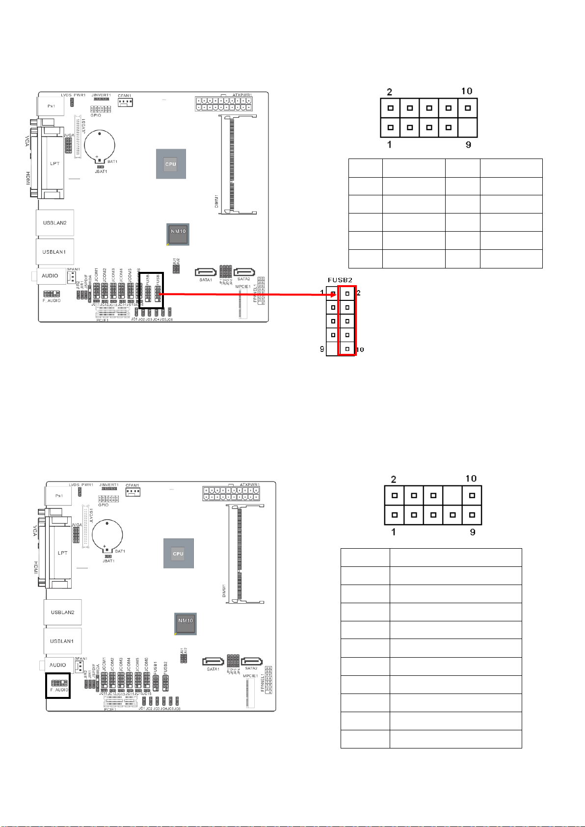
2.2.12 FUSB1/FUSB2 ...................................................................................... 14
2.2.13 F_AUDIO ............................................................................................... 14
2.2.14 JSPDIF1 ................................................................................................ 15
2.2.15 JCOM1-6 ............................................................................................... 15
2.2.16 JCOM1-6 (9th Pin definition) ................................................................. 16
2 EMX-CDT Quick Installation Guide
EMX-CDT Quick Installation Guide
1. Getting Started
1.1 Safety Precautions
Warning!
Always completely disconnect the power cord from your
chassis whenever you work with the hardware. Do not
make connections while the power is on. Sensitive
electronic components can be damaged by sudden power
surges. Only experienced electronics personnel should
open the PC chassis.
Caution!
Always ground yourself to remove any static charge before
touching the CPU card. Modern electronic devices are very
sensitive to static electric charges. As a safety precaution,
use a grounding wrist strap at all times. Place all electronic
components in a static-dissipative surface or static-shielded
bag when they are not in the chassis.
Always note that improper disassembling action could cause damage to the
motherboard. We suggest not removing the heatsink without correct
instructions in any circumstance. If you really have to do this, please contact
us for further support.
1.2 Packing List
Before you begin installing your single board, please make sure that the
following materials have been shipped:
Rear I/O bracket X 1
Quick Installation Guide X 1
Driver/Utility CD X 1
Serial ATA Signal Cable X 1
COM Cable X 1
Motherboard X 1
EMX-CDT Quick Installation Guide 3
EMX-CDT Quick Installation Guide
Title
EMX-CDT
Intel® Atom™ Cedar Trail Mini ITX Motherboard
With Intel® D2550 Processor + NM10 Chipset
Features
Mini-ITX
Onboard Intel® Atom™ processor Cedar Trail
IOH: NM10
One 204-pin DDR3 1066/1033MHZ SO-DIMM socket, supports up to 4GB
Max
1x VGA
1x HDMI
1x 18/24 bit single-channel LVDS
2x Realtek RT8111E PCIe Gigabit Ethernet
1x Mini PCI-e socket
*Mini PCI-e and M-SATA SSD switch through Jumper
1x PCIE x1
Specifications
System
CPU
Onboard Intel® Atom™ Processor D2550 Cedar Trail (1M Cache, 1.86
GHz)
BIOS
AMI 16MBit SPI BIOS
System Chipset
Intel® NM10
I/O Chip
Winbond W83627UHG
System Memory
One 204-pin DDR3 1066/1333MHZ SO-DIMM socket, supports up to 4GB
Max
SSD
NA
Watchdog Timer
Reset : 1 to 255 sec/min per step
H/W Status
Monitor
Monitoring temperature, voltage, and cooling fan
status. Auto throttling control when CPU overheats
Expansion
1x Mini PCI-e socket
*Mini PCI-e and m-SATA SSD switch through Jumper
1x PCIE x1
I/O
MIO
Serial port x 6 internal RS-232 ports with 5V/12V power
2x SATAII Connector(3Gb/s)
1 x 10 pin-headers for VGA output port (The I/O VGA DB15 connector &
1.3 Specifications
4 EMX-CDT Quick Installation Guide
EMX-CDT Quick Installation Guide
1 x 10 pin-headers can’t use in the same time)
USB
8 x USB 2.0/1.1
4 x internal USB port (pin-header) ,4x rear I/O connectors
Parallel Port
1 x LPT port rear I/O connectors
PS2 KB/MS
1 x PS2 keyboard , 1 x PS2 Mouse
DIO
supports 8-bit General Purpose I/O for DI and DO
Display
Chipset
Integrated Intel® Graphics Media Accelerator 3650
(Gfx freq @ 640Mhz) support DX9
Resolution
VGA /HDMI Display: 1920 x 1200
Internal LVDS 1440 x 900
Dual Display
Yes , LVDS+VGA, VGA+HDMI, HDMI+LVDS
Audio
Audio Codec
Realtek ALC661 HD Audio Decoding controller
Audio Interface
Mic-in ,Line out
Support On-board S/PDIF input/output
Ethernet
LAN Chip
2 x Realtek RT8111E PCIe Gigabit Ethernet
Ethernet Interface
10 /100 /1000 Base-Tx Gigabit Ethernet
Mechanical &
Environmental
Power
Requirement
+12V/+5V/5Vsb/+3.3V
Power Type
ATX
Operating Temp.
0 ~ 60°C (32 ~ 140°F)
Storge Temp
-40 ~ 75°C (-40 ~ 167°F)
Operating
Humidity
0 ~ 90% Relative Humidity, Non-condensing
Size (L x W)
6.69” x 6.6” (170mm x 170mm)
Weight
1.058lbs (0.48kg)
EMX-CDT Quick Installation Guide 5

EMX-CDT Quick Installation Guide
2 Hardware
Configuration
6 EMX-CDT Quick Installation Guide

EMX-CDT Quick Installation Guide
2.1 Product Overview
2.1.1 Main board layout
2.1.2 Connecting Rear Panel I/O Devices
EMX-CDT Quick Installation Guide 7

EMX-CDT Quick Installation Guide
Pin No.
Definition
1-2
5V
2-3
3.3V
1-2, Set JLVDS1 Pin1,2,5,6 VDDSAFE as 5V
2-3, Set JLVDS1 Pin1,2,5,6 VDDSAFE as 3.3V
Pin No.
Definition
Pin No.
Definition
1
+3.3V 2 +3.3V
3
GND 4 +5V
5
GND 6 +5V
7
GND 8 PWR OK
9
+5VSB
10
+12V
11
+3.3V
12
-12V
13
GND
14
PS-ON
15
GND
16
GND
17
GND
18
-5V
19
+5V
20
+5V
2.2 Setting Jumpers & Connectors
2.2.1 LVDS _PWR1
2.2.2 20PIN ATXPWR
8 EMX-CDT Quick Installation Guide
EMX-CDT Quick Installation Guide
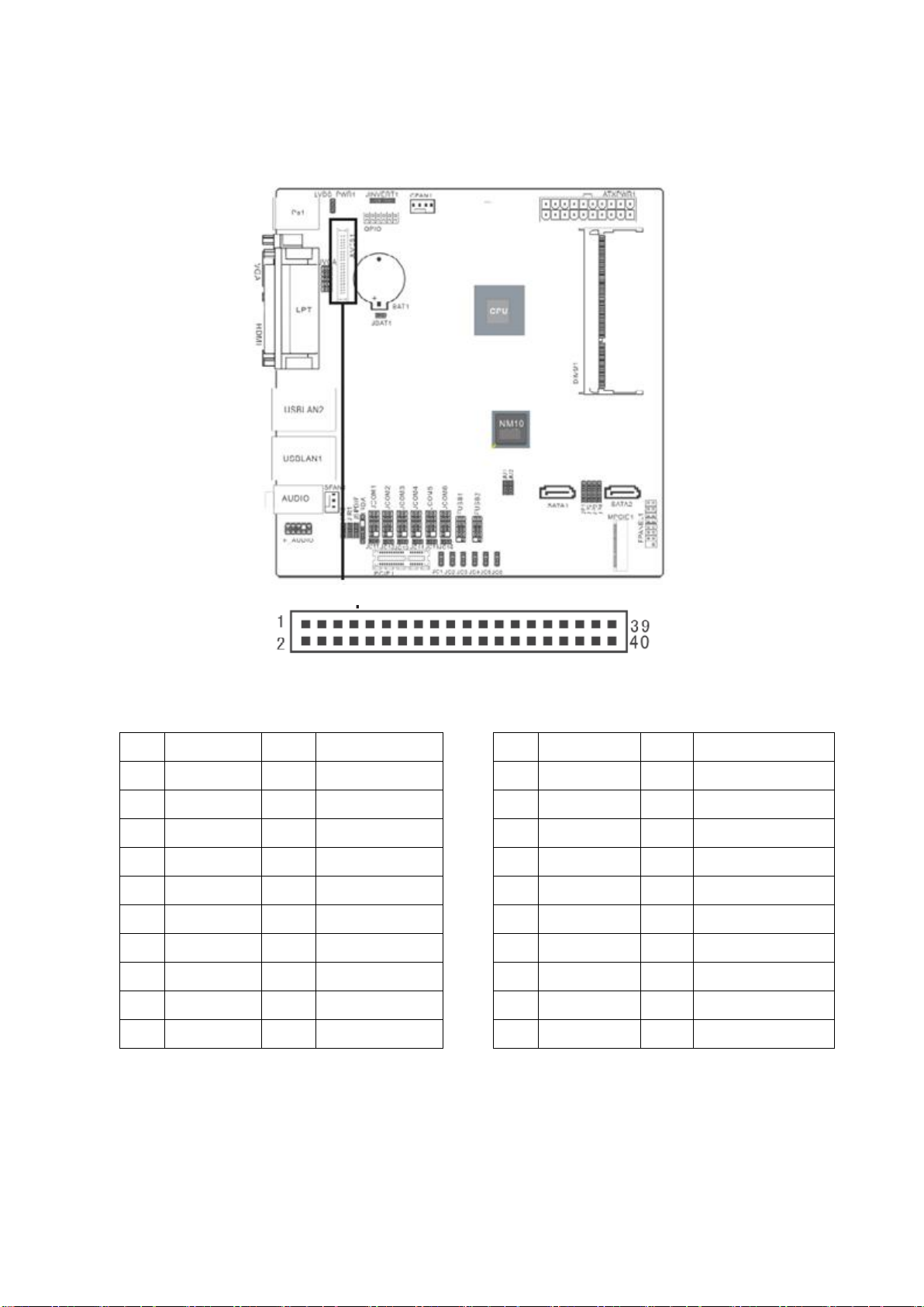
Pin No.
Definition
Pin No.
Definition
1
VDDSAFE
2
VDDSAFE
3
GND 4 GND
5
VDDSAFE
6
VDDSAFE
7
LVDS0_N0 8 NC
9
LVDS0_P0
10
NC
11
GND
12
GND
13
LVDS0_N1
14
NC
15
LVDS0_P1
16
NC
17
GND
18
GND
19
LVDS0_N2
20
NC
Pin No.
Definition
Pin No.
Definition
21
LVDS0_P2
22
NC
23
GND
24
GND
25
LVDS0_CLKN
26
NC
27
LVDS0_CLKP
28
NC
29
GND
30
GND
31
LVDS_DDCPCLK
32
LVDS_DDCPDATA
33
GND
34
GND
35
LVDS0_N3
36
NC
37
LVDS0_P3
38
NC
39
NC
40
LVDS_VCON
2.2.3 JLVDS1
EMX-CDT Quick Installation Guide 9

EMX-CDT Quick Installation Guide
Pin No.
Definition
FUSB2 (USB7)
Mini PCI-e WiFi Card (USB interface)
Mini PCI-e Card
1-2
FUSB2
Enabled
Don’t use USB interface Mini PCI-e card
in the Mini PCI-e slot
Enabled
2-3
MINIPCIE
Disabled
Enabled
Enabled
Pin No.
Definition
1-2
MINIPCIE
2-3
M-SATA
3-4
SATA2
When you want to use Wifi on MINIPCIE1 slot,
please set up JP1-JP4 as 1-2.
When you want to use M-SATA on MINIPCIE1
slot, please set up JP1-JP4 as 2-3.
When you use SATA2 connect, please set up
JP1-JP4 as 3-4.
2.3.4 JU1/ JU2
2.2.5 JP1-JP4
10 EMX-CDT Quick Installation Guide

EMX-CDT Quick Installation Guide
Pin No.
Definition
1-2
COM2
2-3
IR
For COM2, please set up JIR1/ JIR2 as 1-2.
For IR, please set up JIR1/ JIR2 as 2-3.
Pin No.
Definition
Pin No.
Definition
1
5VSB
2
+HD_LED
3
+P_LED
4
-HD_LED
5
-P_LED
6
PS_ON
7
+SPEAK
8
-PS_ON
9
NC
10
RESET
11
NC
12
-RESET
13
-SPEAK
14
+SLEEP_LED
15
KEY
16
-SLEEP_LED
2.2.6 JIR1/ JIR2
2.2.7 FPANEL1
EMX-CDT Quick Installation Guide 11

EMX-CDT Quick Installation Guide
(The I/O VGA DB15 connector & 2 x 5
pin-headers can’t use in the same time)
Pin No.
Definition
Pin No.
Definition
1
GND 2 R 3 GND 4 G 5 GND 6 B
7
HSYNC
8
VSYNC
9
DDC_DATA
10
DDC_CLK
Pin No.
Definition
Pin No.
Definition
1
+5V
2
+12V
3
GPIO
4
GPIO
5
GPIO
6
GPIO
7
GPIO
8
GPIO
9
GPIO
10
GPIO
11
GND
12
GND
2.2.8 JVGA
2.2.9 GPIO
12 EMX-CDT Quick Installation Guide

EMX-CDT Quick Installation Guide
Pin No.
Definition
Pin No.
Definition
1
12V
2
GND
3
BLEN
4
PWM
5
5V
Only for specially used (Can’t send data)
Pin No.
Definition
Pin No.
Definition
1
VCC 2
3
IRRX
4
GND
5
IRTX
2.2.10 JINVERT1
2.2.11 IRDA
EMX-CDT Quick Installation Guide 13
EMX-CDT Quick Installation Guide
Pin No.
Definition
Pin No.
Definition
1
VCC
2
VCC
3
Data 0-
4
Data 1-
5
Data 0+
6
Data 1+
7
GND
8
GND
9
NC(CUT)
10
GND
When JU1/JU2 jumpers are set to 2-3,
FUSB2 (USB7) will be disabled.
(Please refer to P.15 2.3.4 for more information.)
Pin No.
Definition
1
FRONT_MIC
2
GND
3
VREF_OUT
4
5V
5
FRONT_OUT_R
6
AUD_RET_R
7
GND
8
NC(CUT)
9
FRONT_OUT_L
10
AUD_RET_L
2.2.12 FUSB1/FUSB2
2.2.13 F_AUDIO
14 EMX-CDT Quick Installation Guide

EMX-CDT Quick Installation Guide
Pin No.
Definition
1
NC
2
GND
3
OUT
Pin No.
Definition
Pin No.
Definition
1
DCD
2
RXD
3
TXD
4
RTD
5
GND
6
DSR
7
RTS
8
CTS
9
RI
10
NC(CUT)
2.2.14 JSPDIF1
2.2.15 JCOM1-6
EMX-CDT Quick Installation Guide 15

EMX-CDT Quick Installation Guide
COM1 to COM6 9th Pin definition
Pin No.
Pin
Definition
JC11/12/13
CLOSE
RI
JC14/15/16
OPEN
USE JC1-JC6
JC1/2/3
1-2
+5V
JC4/5/6
2-3
+12V
2.2.16 JCOM1-6 (9th Pin definition)
16 EMX-CDT Quick Installation Guide
 Loading...