


EMX-CDD
Intel® Atom™ D2550 Process + NM10 Chipset
Mini ITX Motherboard
User’s Manual
1st Ed – 30 September 2013
Part No. E2047CDDM00R

EMX-CDD User’s Manual
FCC Statement
A Message to the Customer
THIS DEVICE COMPLIES WITH PART 15 FCC RULES. OPERATION IS
SUBJECT TO THE FOLLOWING TWO CONDITIONS:
(1) THIS DEVICE MAY NOT CAUSE HARMFUL INTERFERENCE.
(2) THIS DEVICE MUST ACCEPT ANY INTERFERENCE RECEIVED INCLUDING
INTERFERENCE THAT MAY CAUSE UNDESIRED OPERATION.
THIS EQUIPMENT HAS BEEN TESTED AND FOUND TO COMPLY WITH THE LIMITS
FOR A CLASS "A" DIGITAL DEVICE, PURSUANT TO PART 15 OF THE FCC RULES.
THESE LIMITS ARE DESIGNED TO PROVIDE REASONABLE PROTECTION AGAINST
HARMFUL INTERFERENCE WHEN THE EQUIPMENT IS OPERATED IN A
COMMERCIAL ENVIRONMENT. THIS EQUIPMENT GENERATES, USES, AND CAN
RADIATE RADIO FREQUENCY ENERGY AND, IF NOT INSTATLLED AND USED IN
ACCORDANCE WITH THE INSTRUCTION MANUAL, MAY CAUSE HARMFUL
INTERFERENCE TO RADIO COMMUNICATIONS.
OPERATION OF THIS EQUIPMENT IN A RESIDENTIAL AREA IS LIKELY TO CAUSE
HARMFUL INTERFERENCE IN WHICH CASE THE USER WILL BE REQUIRED TO
CORRECT THE INTERFERENCE AT HIS OWN EXPENSE.
Avalue Customer Services
Each and every Avalue’s product is built to the most exacting specifications to ensure
reliable performance in the harsh and demanding conditions typical of industrial
environments. Whether your new Avalue device is destined for the laboratory or the factory
floor, you can be assured that your product will provide the reliability and ease of operation
for which the name Avalue has come to be known.
Your satisfaction is our primary concern. Here is a guide to Avalue’s customer services. To
ensure you get the full benefit of our services, please follow the instructions below carefully.
Technical Support
We want you to get the maximum performance from your products. So if you run into
technical difficulties, we are here to help. For the most frequently asked questions, you can
easily find answers in your product documentation. These answers are normally a lot more
detailed than the ones we can give over the phone. So please consult the user’s manual
first.
To receive the latest version of the user’s manual; please visit our Web site at:
http://www.avalue.com.tw/
2 EMX-CDD User’s Manual

EMX-CDD User’s Manual
Content
1. Getting Started ............................................................................................................ 6
1.1 Safety Precautions .......................................................................................... 6
1.2 Packing List .................................................................................................... 6
1.3 Document Amendment History ....................................................................... 7
1.4 Manual Objectives .......................................................................................... 8
1.5 Specifications ................................................................................................. 9
1.6 Architecture Overview—Block Diagram........................................................ 11
2. Hardware Configuration ........................................................................................... 12
2.1 Product Overview ......................................................................................... 13
2.2 Installation Procedure ................................................................................... 14
2.3 Jumper and Connector List .......................................................................... 15
2.4 Setting Jumpers & Connectors ..................................................................... 17
2.4.1 Clear CMOS (JBAT1) ............................................................................ 17
2.4.2 Keyboard power select jumper (JKB1) .................................................. 17
2.4.3 Jumper for COM2, IR selection (JIR1~2) .............................................. 18
2.4.4 Jumper for FUSB2, MINIPCIE selection (JU1~2) .................................. 18
2.4.5 Jumper for MPCIE_WIFI_SATA (JP1~4) .............................................. 19
2.4.6 Jumper for LVDS power (LVDS_PWR1) ............................................... 19
2.4.7 Jumper for inverter power (ADJ_PWR1) ............................................... 20
2.4.8 Serial port 1~6 – RI, USE JC1~6 PIN 9 selector (JC11~16) ................. 20
2.4.9 Jumper for Serial port 1~6 selection (JC1~6) ........................................ 21
2.4.10 Jumper for MSATA PWR selection (J_MSATA_P) ............................... 21
2.4.11 General Purpose I/O (GPIO) ................................................................ . 22
2.4.12 Front Panel Switches (FPANEL1) ......................................................... 22
2.4.13 LVDS connector (JLVDS1) .................................................................... 23
2.4.14 Printer (JLPT) ........................................................................................ 24
2.4.15 VGA connector (JVGA) ......................................................................... 24
2.4.16 Inverter connector (JINVERT1) ............................................................. 25
2.4.17 USB Connector 1~3 - USB2.0 (FUSB1~3) ............................................ 25
2.4.18 Front Panel Audio Connection Header (F_AUDIO1) ............................. 26
2.4.19 Serial port 1~6 connector (JCOM1~6) ................................................... 26
2.4.20 Keyboard & Mouse connector (KM1) .................................................... 27
2.4.21 DC power-in connector (J14) ................................................................ 27
2.4.22 SATA Power connector 1~2 (SATA1~2_PWR) ..................................... 28
2.4.23 Speaker Headers (JSPK) ...................................................................... 28
2.4.24 System Fan connector (SFAN1) ........................................................... 29
EMX-CDD User’s Manual 3

EMX-CDD User’s Manual
2.4.25 CPU Fan connector (CFAN1) ................................................................ 29
3.BIOS Setup .................................................................................................................... 30
3.1 Introduction ................................................................................................... 31
3.2 Starting Setup ............................................................................................... 31
3.3 Using Setup .................................................................................................. 32
3.4 Getting Help ................................................................................................. 33
3.5 In Case of Problems ..................................................................................... 33
3.6 BIOS setup ................................................................................................... 34
3.6.1 Main Menu ............................................................................................ 34
3.6.1.1 System Language .......................................................................... 34
3.6.1.2 System Date .................................................................................. 34
3.6.1.3 System Time .................................................................................. 34
3.6.2 Advanced BIOS settings ....................................................................... 35
3.6.2.1 ACPI Settings ................................................................................ 35
3.6.2.2 RTC Wake Settings ....................................................................... 36
3.6.2.3 CPU Configuration ......................................................................... 37
3.6.2.4 IDE Configuration ........................................................................... 38
3.6.2.5 USB Configuration ......................................................................... 38
3.6.2.6 Power Management ....................................................................... 39
3.6.2.7 W83627UHG Super IO Configuration ............................................ 40
3.6.2.8 WatchDogTimer Settings ............................................................... 47
3.6.2.9 W83627UHG HW Monitor .............................................................. 47
3.6.3 Chipset ..................................................................................................... 48
3.6.3.1 Host Bridge .................................................................................... 48
3.6.3.2 South Bridge .................................................................................. 50
3.6.4 Boot settings ......................................................................................... 52
3.6.5 Security ................................................................................................. 53
3.6.5.1 Administrator Password ................................................................. 53
3.6.5.2 User Password............................................................................... 53
3.6.6 Save & Exit ............................................................................................ 54
3.6.6.1 Save Changes and Exit ................................................................. 54
3.6.6.2 Discard Changes and Exit ............................................................. 54
3.6.6.3 Save Changes and Reset .............................................................. 55
3.6.6.4 Discard Changes and Reset .......................................................... 55
3.6.6.5 Save Changes ............................................................................... 55
3.6.6.6 Discard Changes ........................................................................... 55
3.6.6.7 Restore Defaults ............................................................................ 55
3.6.6.8 Save as User Defaults ................................................................... 55
3.6.6.9 Restore User Defaults .................................................................... 55
4 EMX-CDD User’s Manual

EMX-CDD User’s Manual
4. Drivers Installation....................................................................................................... 56
4.1 Install Chipset Driver .................................................................................... 57
4.2 Install VGA Driver ......................................................................................... 59
4.3 Install LAN Driver (For Realtek 8111E Gigabit Ethernet) ............................. 61
4.4 Install Audio Driver (For Realtek ALC661 HD Audio) ................................... 62
5. Mechanical Drawing .................................................................................................... 63
EMX-CDD User’s Manual 5
EMX-CDD User’s Manual
1. Getting Started
1.1 Safety Precautions
Warning!
Always completely disconnect the power cord from your
chassis whenever you work with the hardware. Do not
make connections while the power is on. Sensitive
electronic components can be damaged by sudden power
surges. Only experienced electronics personnel should
open the PC chassis.
Caution!
Always ground yourself to remove any static charge before
touching the CPU card. Modern electronic devices are very
sensitive to static electric charges. As a safety precaution,
use a grounding wrist strap at all times. Place all electronic
components in a static-dissipative surface or static-shielded
bag when they are not in the chassis.
Always note that improper disassembling action could cause damage to the
motherboard. We suggest not removing the heatsink without correct
instructions in any circumstance. If you really have to do this, please contact
us for further support.
1.2 Packing List
Before you begin installing your single board, please make sure that the
following materials have been shipped:
Quick Installation Guide X 1
Driver/Utility CD X 1
Serial ATA Signal Cable X 1
Serial ATA Power Cable X 1
Screw X 2
Motherboard X 1
6 EMX-CDD User’s Manual

EMX-CDD User’s Manual
Revision
Date
By
Comment
1st
September
2013
Avalue
Initial Release
1.3 Document Amendment History
EMX-CDD User’s Manual 7

EMX-CDD User’s Manual
1.4 Manual Objectives
This manual describes in details Avalue Technology EMX-CDD Single Board.
We have tried to include as much information as possible but we have not duplicated
information that is provided in the standard IBM Technical References, unless it proved to
be necessary to aid in the understanding of this board.
We strongly recommend that you study this manual carefully before attempting to set up
EMX-CDD series or change the standard configurations. Whilst all the necessary
information is available in this manual we would recommend that unless you are confident,
you contact your supplier for guidance.
If you have any suggestions or find any errors regarding this manual and want to inform us
of these, please contact our Customer Service department with the relevant details.
8 EMX-CDD User’s Manual
EMX-CDD User’s Manual
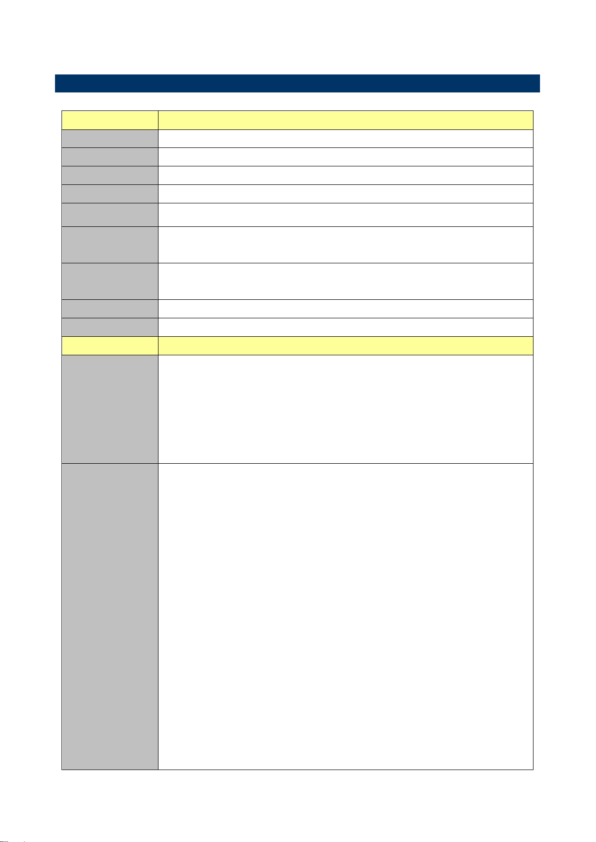
System
CPU
Intel® Atom™ processor D2550 Processor
BIOS
AMI uEFI BIOS, 16Mbit SPI Flash ROM
System Chipset
Intel® NM10
I/O Chip
Winbond W83627UHG
System Memory
1 x 204-pin DDR3 1066/1333 MHz SODIMMs, up to 4GB
Watchdog Timer
H/W Reset, 1sec. – 65535sec./min
1sec. or 1min. step
H/W Status
Monitor
CPU & system temperature monitoring
Voltages monitoring
Buzzer
Buzzer onboard
Expansion
1 x Mini PCI-e (Mini PCI-e and mSATA SSD is Switchable Through Jumper)
I/O
Rear Side External
I/O Connector
2 x RJ-45
1 x dual deck USB 2.0 connectors
1 x VGA
1 x HDMI
1 x Mic-In and 1 x Line-out
1 x DC Jack
Internal I/O
Connector
Storage:
- 1 x mSATA connector (The mSATA and SATA II is Switchable Through
Jumper)
- 2 x SATA II connector
- 2 x SATA power connectors
COM:
- COM1~6: support RS-232 connector, Pin 9 without / +5V&+12V supported
GPIO: 8 bits
1 x LVDS
1 x Mini PCI-e slot
3 x 2 x 5 pin, pitch 2.54mm connector for USB 2.0
1 x 1 x 4 pin, pitch 2.50mm CPU fan connector with smart fan function
supported
1 x horizontal type battery connector
1 x 2 x 8 pin, pitch 2.54mm connector for front panel
1 x 2 x 2 pin ATX power connector for DC 12V input
1 x 2 x 20 pin, pitch 1.25mm connector for LVDS
1.5 Specifications
EMX-CDD User’s Manual 9

EMX-CDD User’s Manual
1 x 5 pin, pitch 2.54mm connector for Inverter
1 x 2 x 5 pin, pitch 2.54mm connector for Audio
1 x 3 pin, pitch 2.54mm connector for LVDS PWR selection
1 x 2 x 12 pin, pitch 2.54mm connector for printer port
1 x 2 x 5 pin, pitch 2.54mm connector for VGA
1 x 2 x 5 pin, pitch 2.54mm connector for Keyboard & Mouse
1 x 1 x 4 pin, pitch 2.00mm connector for Amplifier
Display
Chipset
Intel NM10 integrated
Resolution
HDMI:1920 x 1200
VGA:1920 x 1200
LVDS
1CH 18/24bits LVDS 1400 x 900
Audio
Chipset
Realtek ALC661 HD Audio Decoding Controller.
Audio Interface
Mic-In, Line-In
Audio Amplifier
Realtek ALC105 Stereo Class-D 3W x 2
Ethernet
Chipset
2 x Realtek RTL8111E PCI-Express Gigabit Ethernet
Ethernet Interface
10/100/1000 Gigabit Ethernet
Mechanical &
Environmental
Power
Requirement
DC in +12V
Power Type
Single power +12V Power input / ATX mode
ACPI
Single power ATX Support S0,S1, S3, S4, S5
ACPI 3.0 Compliant
Operating Temp.
0°C ~60°C
Storage Temp.
-40°C ~75°C
Operating
Humidity
0%~90% relative humidity, non-condensing
Size (L x W)
6.7" x 6.7" (170mm x 170mm)
Weight
0.40 kg
Note: The USB keyboard and USB mouse can’t support wake up form S4 mode.
10 EMX-CDD User’s Manual
EMX-CDD User’s Manual
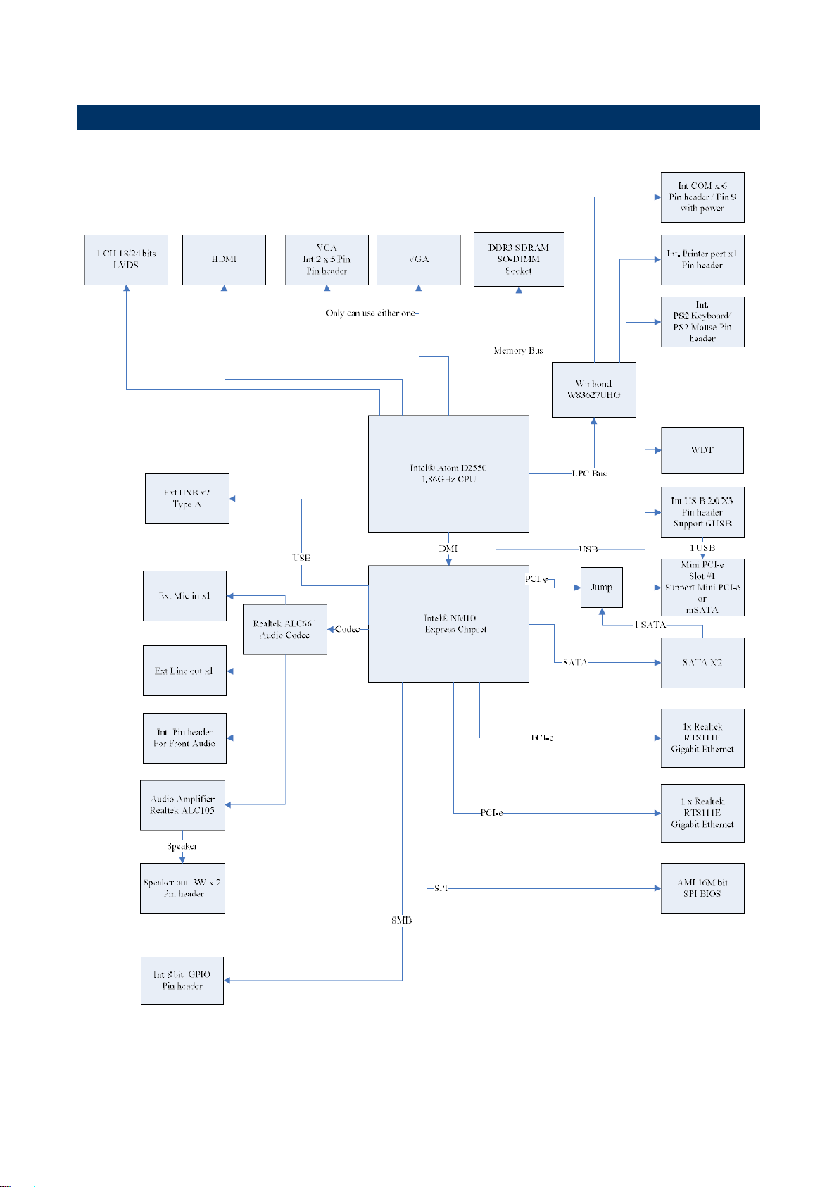
1.6 Architecture Overview—Block Diagram
The following block diagram shows the architecture and main components of EMX-CDD.
EMX-CDD User’s Manual 11

EMX-CDD User’s Manual
2. Hardware
Configuration
12 EMX-CDD User’s Manual
EMX-CDD User’s Manual
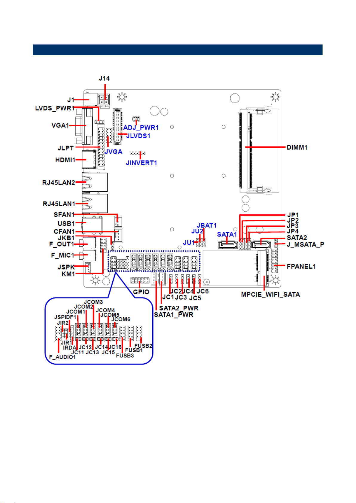
2.1 Product Overview
EMX-CDD User’s Manual 13

EMX-CDD User’s Manual
2.2 Installation Procedure
This chapter explains you the instructions of how to setup your system.
1. Turn off the power supply.
2. Insert the DIMM module (be careful with the orientation).
3. Insert all external cables for hard disk, floppy, keyboard, mouse, USB etc. except for flat
panel. A CRT monitor must be connected in order to change BIOS settings to support flat
panel.
4. Connect power supply to the board via the AC/DC Adapter.
5. Turn on the power.
6. Enter the BIOS setup by pressing the delete key during boot up. Use the "Save & Exit \
Restore Defaults" feature.
7. If TFT panel display is to be utilized, make sure the panel voltage is correctly set before
connecting the display cable and turning on the power.
14 EMX-CDD User’s Manual
EMX-CDD User’s Manual
Jumpers
Label
Function
Note
LVDS_PWR1
Jumper for LVDS PWR selection
1 x 3 header, pitch 2.54 mm
JP1~4
Jumper for MPCIE_WIFI_SATA
1 x 4 header, pitch 2.54 mm
ADJ_PWR1
Jumper for inverter power
2 x 3 header, pitch 2.00 mm
JKB1
Keyboard power select jumper
1 x 3 header, pitch 2.54 mm
JIR1~2
Jumper for COM2, IR selection
1 x 3 header, pitch 2.54 mm
JC1~6
Jumper for Serial port 1~6 selection
1 x 3 header, pitch 2.54 mm
JC11~16
Serial port 1~6 – RI, USE JC1~6
PIN 9 selector
1 x 2 header, pitch 2.54 mm
JU1~2
Jumper for FUSB2, MINIPCIE selection
1 x 3 header, pitch 2.54 mm
JBAT1
Clear CMOS
1 x 3 header, pitch 2.54 mm
J_MSATA_P
Jumper for MSATA PWR selection
1 x 3 header, pitch 2.54 mm
2.3 Jumper and Connector List
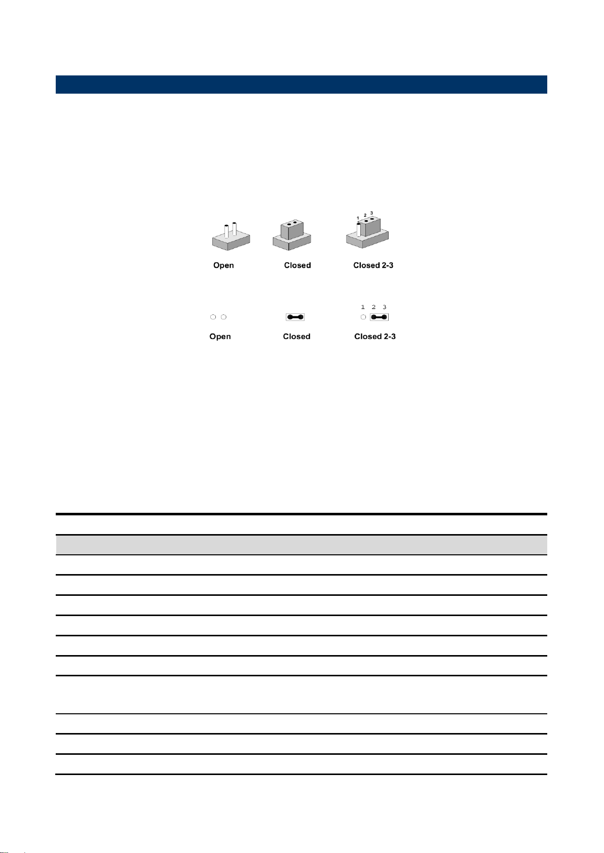
You can configure your board to match the needs of your application by setting jumpers. A
jumper is the simplest kind of electric switch.
It consists of two metal pins and a small metal clip (often protected by a plastic cover) that
slides over the pins to connect them. To “close” a jumper you connect the pins with the clip.
To “open” a jumper you remove the clip. Sometimes a jumper will have three pins, labeled 1,
2, and 3. In this case, you would connect either two pins.
The jumper settings are schematically depicted in this manual as follows:
A pair of needle-nose pliers may be helpful when working with jumpers.
Connectors on the board are linked to external devices such as hard disk drives, a
keyboard, or floppy drives. In addition, the board has a number of jumpers that allow you to
configure your system to suit your application.
If you have any doubts about the best hardware configuration for your application, contact
your local distributor or sales representative before you make any changes.
The following tables list the function of each of the board’s jumpers and connectors.
EMX-CDD User’s Manual 15

EMX-CDD User’s Manual
Connectors
Label
Function
Note
FPANEL1
Front Panel Switches
2 x 8 header, pitch 2.54 mm
MPCIE_WIFI_SATA
PCIE signal selector
HDMI1
HDMI connector
J1
ATX power connector for DC 12V input
JSPK
Speaker connector
1 x 4 wafer, pitch 2.00 mm
J14
DC power-in connector
2 x 2 header, pitch 4.20 mm
JCOM1~6
Serial port 1~6 connector
2 x 5 header, pitch 2.00 mm
GPIO
General Purpose I/O
2 x 6 header, pitch 2.54 mm
JLVDS1
LVDS connector
2 x 20 wafer, pitch 1.25 mm
SATA1~2
Serial ATA connector 1~2
SATA1~2_PWR
SATA Power connector 1~2
1 x 4 header, pitch 2.54 mm
F_MIC1
Mic-in audio jack
3.5mm phone jack
F_OUT1
Line-out audio jack
3.5mm phone jack
RJ45LAN1~2
LAN port 1~2
F_USB1~3
USB connector 1~3
2 x 5 header, pitch 2.54 mm
USB1
USB connector
SFAN1
System Fan connector
1 x 3 wafer, pitch 2.54 mm
CFAN1
CPU Fan connector
1 x 4 wafer, pitch 2.50 mm
JLPT
Printer
2 x 12 header, pitch 2.54 mm
DIMM1
DDR3 SODIMM socket
VGA1
VGA connector
JVGA
VGA connector
2 x 5 header, pitch 2.54 mm
JINVERT1
Inverter connector
1 x 5 header, pitch 2.54 mm
KM1
Keyboard & Mouse connector
2 x 5 header, pitch 2.54 mm
F_AUDIO1
Front Panel Audio Connection Header
2 x 5 header, pitch 2.54 mm
JSPIDF1
Sony/Philips Digital Interface
1 x 5 header, pitch 2.54 mm
IRDA
IRDA connector (not supported)
1 x 5 header, pitch 2.00 mm
16 EMX-CDD User’s Manual
EMX-CDD User’s Manual
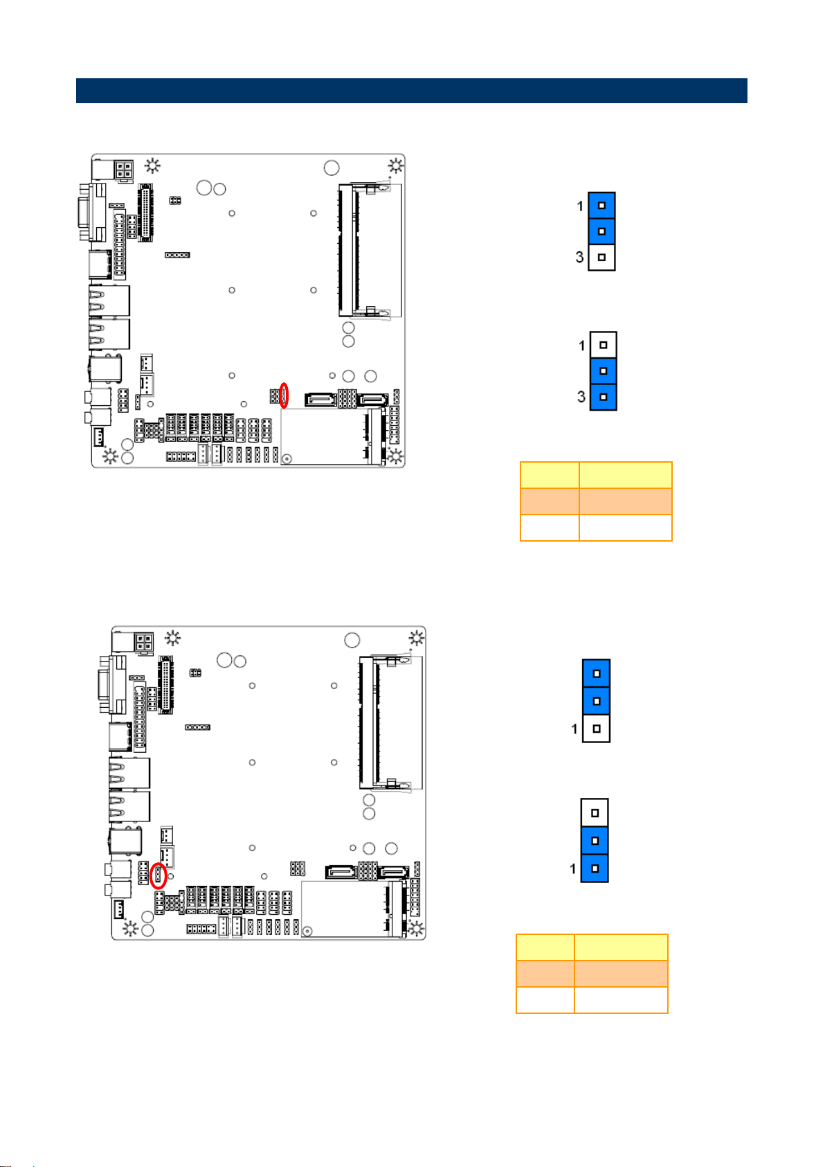
* Default
Normal*
Clear CMOS
Pin
Define
1-2
Normal
2-3
Clear CMOS
* Default
Disabled*
Enabled
Pin
Define
1-2
Disabled
2-3
Enabled
2.4 Setting Jumpers & Connectors
2.4.1 Clear CMOS (JBAT1)
2.4.2 Keyboard power select jumper (JKB1)
EMX-CDD User’s Manual 17
EMX-CDD User’s Manual
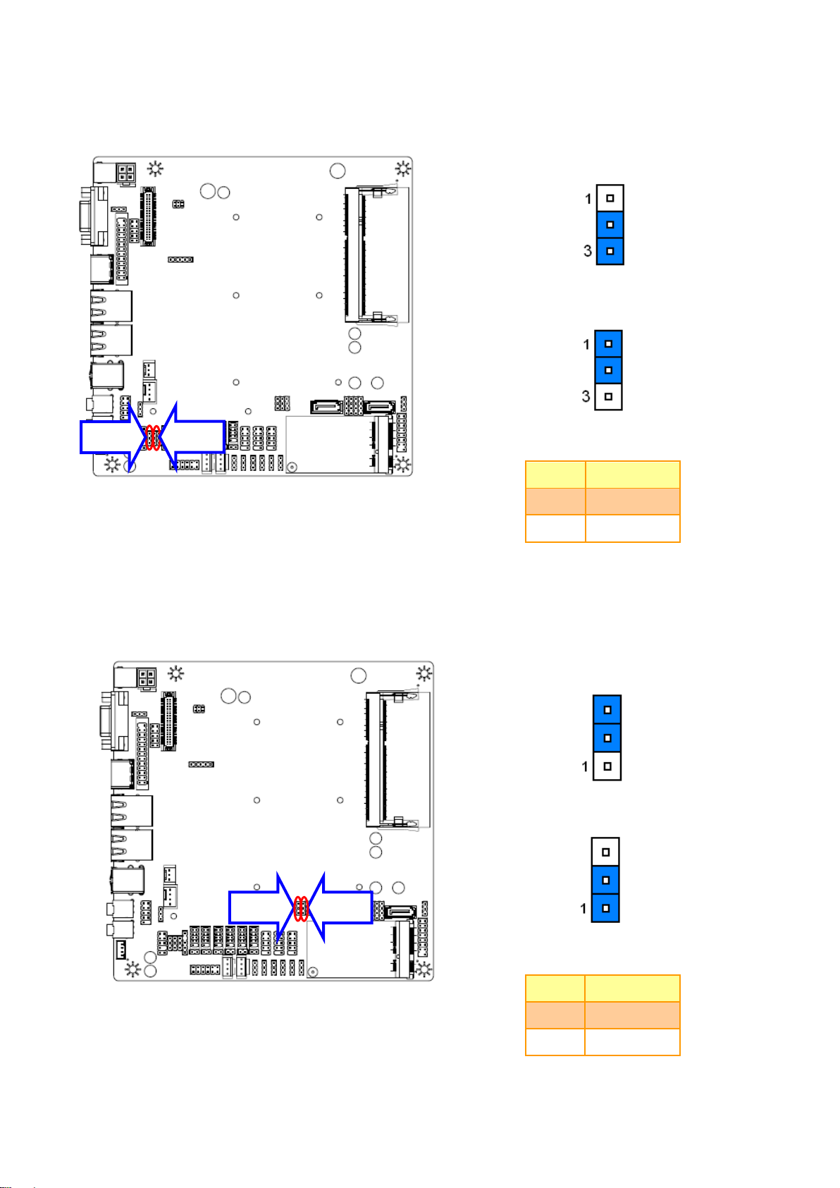
* Default
IR*
COM
Pin
Define
1-2
COM
2-3
IR
Note: IR is not functional.
* Default
FUSB2*
MINIPCIE
Pin
Define
1-2
FUSB2
2-3
MINIPCIE
JIR2
JIR1
JU2
JU1
2.4.3 Jumper for COM2, IR selection (JIR1~2)
2.4.4 Jumper for FUSB2, MINIPCIE selection (JU1~2)
18 EMX-CDD User’s Manual
EMX-CDD User’s Manual
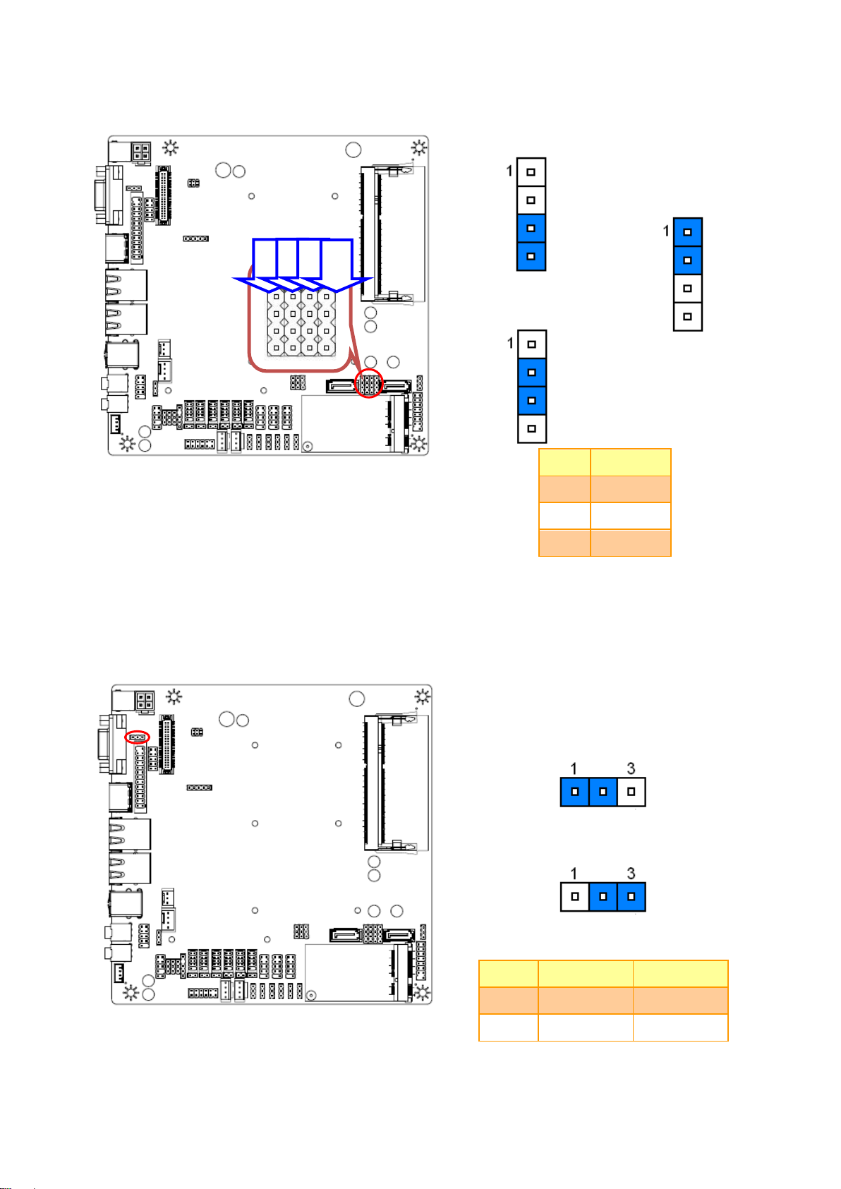
* Default
Note: SATA 2 bond together with M-SATA, it can only
work either way at one time.
SATA2*
M-SATA
MINIPCIE
PIN
Define
1-2
MINIPCIE
2-3
M-SATA
3-4
SATA2
* Default
5V*
3.3V
Pin
Define
Max current
1-2
5V
1A
2-3
3.3V
1A
JP1
JP2
JP3
JP4
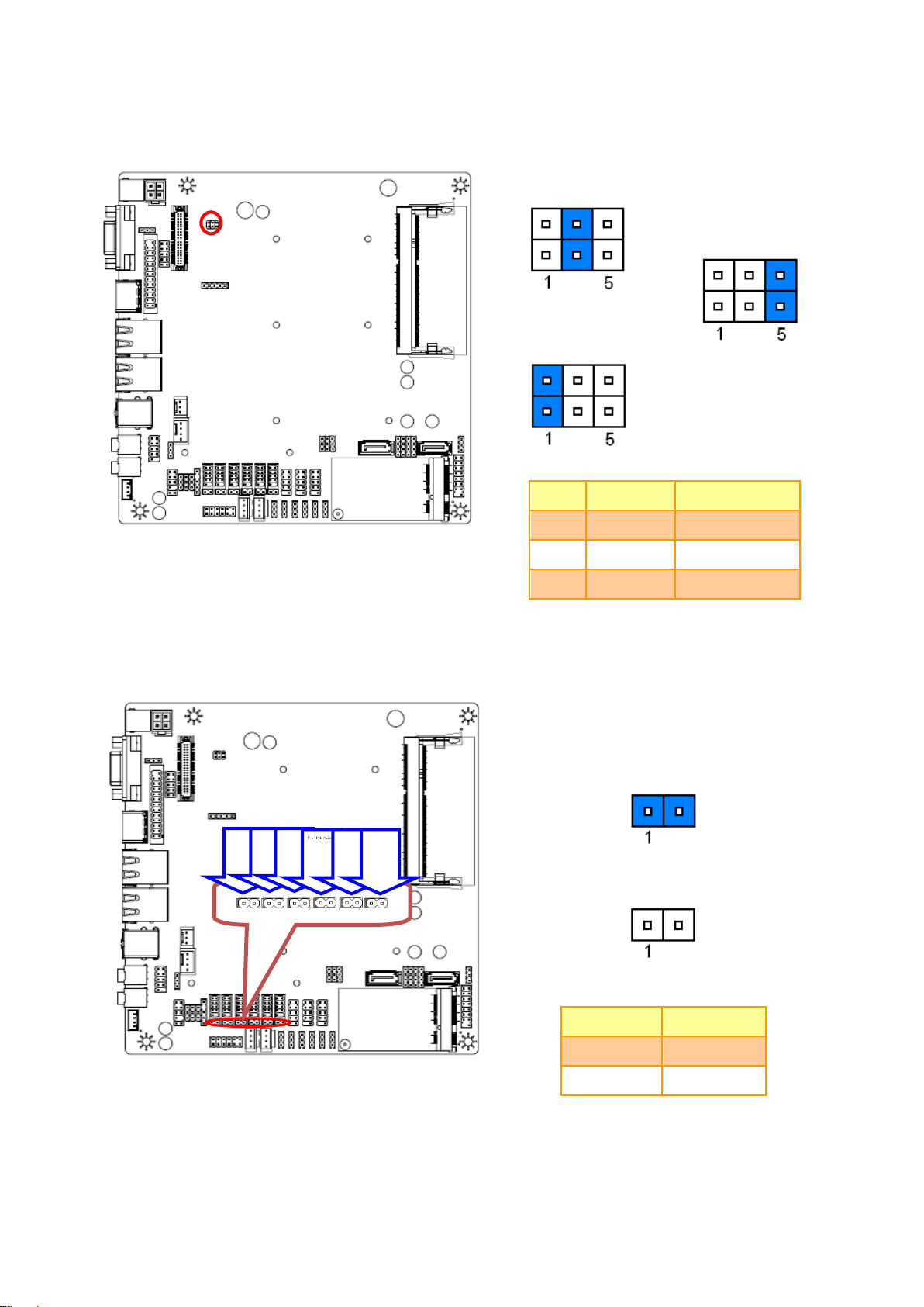
2.4.5 Jumper for MPCIE_WIFI_SATA (JP1~4)
2.4.6 Jumper for LVDS power (LVDS_PWR1)
EMX-CDD User’s Manual 19
EMX-CDD User’s Manual
* Default
5V*
5V
0
PIN
Define
Max current
1-2
5V
1A
3-4
5V
1A
5-6 0 1A
* Default
RI*
USE JC1_JC6
PIN Option
Define
CLOSE
RI
OPEN
USE JC_JC6
JC11
JC12
JC13
JC14
JC15
JC16
2.4.7 Jumper for inverter power (ADJ_PWR1)
2.4.8 Serial port 1~6 – RI, USE JC1~6 PIN 9 selector (JC11~16)
20 EMX-CDD User’s Manual

EMX-CDD User’s Manual
+5V
+12V
PIN
Define
Max current
1-2
+5V
1A
2-3
+12V
1A
* Default
M_PCIE*
M_SATA
Pin
Define
1-2
M_SATA
2-3
M_PCIE
JC1
JC2
JC3
JC4
JC5
JC6
2.4.9 Jumper for Serial port 1~6 selection (JC1~6)
2.4.10 Jumper for MSATA PWR selection (J_MSATA_P)
EMX-CDD User’s Manual 21

EMX-CDD User’s Manual
Signal
PIN
PIN
Signal
+5V
1 2 +12V
GPIO
3 4 GPIO
GPIO
5 6 GPIO
GPIO
7 8 GPIO
GPIO
9
10
GPIO
GND
11
12
GND
Signal
PIN
PIN
Signal
5VSB
1
2
+HD_LED
+P_LED
3
4
-HD_LED
-P_LED
5
6
PS_ON
+SPEAK
7
8
-PS_ON
NC
9
10
RESET
NC
11
12
-RESET
-SPEAK
13
14
+SLPLED
16
-SLPLED
2.4.11 General Purpose I/O (GPIO)
2.4.12 Front Panel Switches (FPANEL1)
22 EMX-CDD User’s Manual

EMX-CDD User’s Manual
Note: Mapping connector DF13-40DS-1.25C
(1.0mm).
Signal
PIN
PIN
Signal
VDDPAEA
2 1 VDDPAEA
GND
4 3 GND
VDDPAEA
6 5 VDDPAEA
NC
8 7 LVDS0_N0
NC
10 9 LVDS0_P0
GND
12
11
GND
NC
14
13
LVDS0_N1
NC
16
15
LVDS0_P1
GND
18
17
GND
NC
20
19
LVDS0_N2
NC
22
21
LVDS0_P2
GND
24
23
NC
NC
26
25
LVDS0_CLKN
NC
28
27
LVDS0_CLKP
GND
30
29
GND
LVDS_DDCPDATA
32
31
LVDS_DDCPCLK
GND
34
33
GND
NC
36
35
LVDS0_N3
NC
38
37
LVDS0_P3
LVDS_VCON
40
39
NC
2.4.13 LVDS connector (JLVDS1)
EMX-CDD User’s Manual 23

EMX-CDD User’s Manual
Signal
PIN
PIN
Signal
25
SLCT
GND
24
23
PE
GND
22
21
BUSY
GND
20
19
ACK
GND
18
17
PD7
GND
16
15
PD6
GND
14
13
PD5
GND
12
11
PD4
GND
10 9 PD3
SLIN
8 7 PD2
INIT
6 5 PD1
ERR
4 3 PD0
AFD
2 1 STB
Note: It can only use either D-SUB connector or Pin
Header.
Signal
PIN
PIN
Signal
DDC_CLK
10 9 DDC_DATA
VSYNC
8 7 HSYNC
BLUE
6 5 GND
GREEN
4 3 GND
RED
2 1 GND
2.4.14 Printer (JLPT)
2.4.15 VGA connector (JVGA)
24 EMX-CDD User’s Manual

EMX-CDD User’s Manual
PIN
Signal
Max current
1
12V
1A 2 GND
3 BLEN
4 PWM
5 5V
1A
Signal
PIN
PIN
Signal
VCC
1 2 VCC
DATA-
3 4 DATA-
DATA+
5 6 DATA+
GND
7 8 GND
10
GND
FUSB3
FUSB1
FUSB2
2.4.16 Inverter connector (JINVERT1)
2.4.17 USB Connector 1~3 - USB2.0 (FUSB1~3)
EMX-CDD User’s Manual 25

EMX-CDD User’s Manual
Signal
PIN
PIN
Signal
FROT1L
1 2 GND
PROT1R
3 4 PRESENCE#
PORT2R
5 6 SENSE1_RETURN
SENSE_SEND
7
PORT2L
9
10
SENSE2_RETURN
Signal
PIN
PIN
Signal
DCD
1 2 RXD
TXD
3 4 DTR
GND
5 6 DSR
RTS
7 8 CTS
RI
9
JCOM1
JCOM2
JCOM3
JCOM4
JCOM5
JCOM6
2.4.18 Front Panel Audio Connection Header (F_AUDIO1)
2.4.19 Serial port 1~6 connector (JCOM1~6)
26 EMX-CDD User’s Manual

EMX-CDD User’s Manual
Signal
PIN
PIN
Signal
MDT
1 2 KB_DATA
MCK
3 4 KB_CLK
GND
5 6 GND
VCC
7 8 VCC
KEY
9
Signal
PIN
PIN
Signal
GND
1 2 GND
+12V
3 4 +12V
2.4.20 Keyboard & Mouse connector (KM1)
2.4.21 DC power-in connector (J14)
EMX-CDD User’s Manual 27

EMX-CDD User’s Manual
PIN
Signal
Max current
4
5V
1A
3
GND
2
GND
1 12V
1A
PIN
Signal
4
INTSPR-
3
INTSPR+
2
INTSPL-
1
INTSPL+
Note: Support 3W X 2 speaker.
Mapping Connector PHR-4
SATA1_PWR
SATA2_PWR
2.4.22 SATA Power connector 1~2 (SATA1~2_PWR)
2.4.23 Speaker Headers (JSPK)
28 EMX-CDD User’s Manual

EMX-CDD User’s Manual
PIN
Signal
3
Ground
2
+12V
1
RPM
PIN
Signal
1
Ground
2
+12V
3
RPM
4
Control
2.4.24 System Fan connector (SFAN1)
2.4.25 CPU Fan connector (CFAN1)
EMX-CDD User’s Manual 29

EMX-CDD User’s Manual
3.BIOS Setup
30 EMX-CDD User’s Manual

EMX-CDD User’s Manual
3.1 Introduction
The BIOS setup program allows users to modify the basic system configuration. In this
following chapter will describe how to access the BIOS setup program and the
configuration options that may be changed.
3.2 Starting Setup
The BIOS is immediately activated when you first power on the computer. The BIOS reads
the system information contained in the NVRAM and begins the process of checking out
the system and configuring it. When it finishes, the BIOS will seek an operating system on
one of the disks and then launch and turn control over to the operating system.
While the BIOS is in control, the Setup program can be activated in one of two ways:
By pressing <Del> immediately after switching the system on, or
By pressing the <Del> key when the following message appears briefly at the bottom of the
screen during the POST (Power On Self Test).
Press DEL to enter setup, F11 to popup menu
If the message disappears before you respond and you still wish to enter Setup, restart the
system to try again by turning it OFF then ON or pressing the "RESET" button on the
system case. You may also restart by simultaneously pressing <Ctrl>, <Alt>, and <Delete>
keys. If you do not press the keys at the correct time and the system does not boot, an error
message will be displayed and you will again be asked to.
Press DEL to enter setup, F11 to popup menu
EMX-CDD User’s Manual 31

EMX-CDD User’s Manual
Button
Description
↑
Move to previous item
↓
Move to next item
←
Move to the item in the left hand
→
Move to the item in the right hand
Esc key
Main Menu -- Quit and not save changes into NVRAM
Status Page Setup Menu and Option Page Setup Menu -- Exit current page and
return to the pervious page or Main Menu
+ key
Increase the numeric value or make changes
- key
Decrease the numeric value or make changes
F1 key
General help, only for Status Page Setup Menu and Option Page Setup Menu
F7 key
Previous Values
F8 key
Fail-Safe Values
F9 key
Optimized Defaults
F10 key
Save and Exit
3.3 Using Setup
In general, you use the arrow keys to highlight items, press <Enter> to select, use the
PageUp and PageDown keys to change entries, press <F1> for help and press <Esc> to
quit. The following table provides more detail about how to navigate in the Setup program
using the keyboard.
Navigating Through The Menu Bar
Use the left and right arrow keys to choose the menu you want to be in.
Note: Some of the navigation keys differ from one screen to another.
To Display a Sub Menu
Use the arrow keys to move the cursor to the sub menu you want. Then press
<Enter>. A “” pointer marks all sub menus.
32 EMX-CDD User’s Manual

EMX-CDD User’s Manual
3.4 Getting Help
Press F1 to pop up a small help window that describes the appropriate keys to use and the
possible selections for the highlighted item. To exit the Help Window press <Esc> or the F1
key again.
3.5 In Case of Problems
If, after making and saving system changes with Setup, you discover that your computer no
longer is able to boot, the BIOS supports an override to the NVRAM settings which resets
your system to its defaults.
The best advice is to only alter settings which you thoroughly understand. To this end, we
strongly recommend that you avoid making any changes to the chipset defaults. These
defaults have been carefully chosen by both AMI and your systems manufacturer to
provide the absolute maximum performance and reliability. Even a seemingly small change
to the chipset setup has the potential for causing you to use the override.
EMX-CDD User’s Manual 33

EMX-CDD User’s Manual
3.6 BIOS setup
Once you enter the BIOS Setup Utility, the Main Menu will appear on the screen. The Main
Menu allows you to select from several setup functions and exit choices. Use the arrow
keys to select among the items and press <Enter> to accept and enter the sub-menu.
3.6.1 Main Menu
This section allows you to record some basic hardware configurations in your computer and
set the system clock.
3.6.1.1 System Language
Use this option to select system language
3.6.1.2 System Date
Use the system date option to set the system date. Manually enter the day, month and
year.
3.6.1.3 System Time
Use the system time option to set the system time. Manually enter the hours, minutes and
seconds.
Note: BIOS setup screens shown in this chapter are for reference only, and may
not exactly match what you see on your screen. Visit the Avalue website
(www.avalue.com.tw) to download the latest product and BIOS information.
34 EMX-CDD User’s Manual

EMX-CDD User’s Manual
Item
Options
Description
Launch PXE OpROM
Disable[Default]
Enable
Controls the execution of UEFI and Legacy
PXE OpROM.
3.6.2 Advanced BIOS settings
This section allows you to configure your CPU and other system devices for basic operation
through the following sub-menus.
3.6.2.1 ACPI Settings
EMX-CDD User’s Manual 35

EMX-CDD User’s Manual
Item
Options
Description
Enable ACPI Auto
Configuration
Disabled
Enabled[Default]
Enable or Disable BIOS ACPI Auto
Configuration.
Enable Hibernation
Disabled
Enabled[Default]
Enable or Disable System ability to Hibernate
(OS/S4 Sleep State). This option may be not
effective with some OS.
ACPI Sleep State
Suspend Disabled
S1 only(CPU Stop Clock)
S3 only(Suspend to RAM)
[Default]
Select ACPI sleep state the system will enter
when the SUSPEND button is pressed.
Lock Legacy Resources
Disabled
Enabled[Default]
Enable or Disable Lock of Legacy Resources.
S3 Video Repost
Disabled[Default]
Enabled
Enable or Disable S3 Video Repost.
Item
Options
Description
Wake system with Fixed Time
Disabled[Default]
Enabled
Enable or Disable System wake on alarm
event. When enabled, System will wake on the
hr::min::sec specified.
3.6.2.2 RTC Wake Settings
36 EMX-CDD User’s Manual

EMX-CDD User’s Manual
Item
Options
Description
CPU C1E Support
Disabled[Default]
Enabled
Enable/Disable CPU C1E state.
Hyper-Threading
Disabled[Default]
Enabled
Enable for Windows XP and Linux (OS optimized
for Hyper – Threading Technology) and Disabled
for other OS (OS not optimized for Hyper –
Threading Technology).
Execute Disable Bit
Disabled[Default]
Enabled
XD can prevent certain classes of malicious buffer
overflow attacks when combined with a supporting
OS (Windows Server 2003 SP1, Windows XP SP2,
SuSE Linux 9.2, RedHat Enterprise 3 Update 3.)
Limit CPUID Maximum
Disabled[Default]
Enabled
Disabled for Windows XP.
3.6.2.3 CPU Configuration
Use the CPU configuration menu to view detailed CPU specification and configure the
CPU.
EMX-CDD User’s Manual 37

EMX-CDD User’s Manual
Item
Options
Description
SATA Controller(s)
Disabled
Enabled[Default]
SATA Ports (0-3) Device Names if Present and
Enabled.
Configure SATA as
IDE[Default]
AHCI
Select a configuration for SATA Controller.
3.6.2.4 IDE Configuration
3.6.2.5 USB Configuration
38 EMX-CDD User’s Manual

EMX-CDD User’s Manual
Item
Options
Description
Legacy USB Support
Enabled[Default]
Disabled
Auto
Enables Legacy USB support. AUTO option
disables legacy support if no USB devices are
connected. DISABLE option will keep USB devices
available only for EFI applications.
EHCI Hand-off
Enabled
Disabled[Default]
This is a workaround for OSes without EHCI
hand-off support. The EHCI ownership change
should be claimed by EHCI driver.
USB transfer time-out
1 sec
5 sec
10 sec
20 sec[Default]
This time-out value for Control, Bulk, and Interrupt
transfers.
Device reset time-out
10 sec
20 sec[Default]
30 sec
40 sec
USB mass storage device Start Unit command
time-out.
Device power-up delay
Auto[Default]
Manual
Maximum time the device will take before it
properly reports itself to the Host Controller. ‘Auto’
uses default value: for a Root port it is 100 ms, for a
Hub port the delay is taken from Hub descriptor.
Item
Options
Description
Power On By PS/2 Keyboard
Disabled [Default]
Anykey
Password
Power On By PS/2 Keyboard.
Power On By PS/2 Mouse
Enabled
Disabled[Default]
Power On By PS/2 Mouse.
Wake By PME
Enabled
Disabled[Default]
Wake By PME.
AC Power Loss
Power Off[Default]
Power On
Last State
AC Power Loss.
3.6.2.6 Power Management
EMX-CDD User’s Manual 39

EMX-CDD User’s Manual
Item
Description
Serial Port 1/2/3/4/5/6
Configuration
Set Parameters of Serial Port 1/2/3/4/5/6 (COMA/B/C/D/E/F).
Parallel Port Configuration
Set Parameters of Parallel Port (LPT/LPTE).
3.6.2.7 W83627UHG Super IO Configuration
3.6.2.7.1 Serial Port 1 Configuration
40 EMX-CDD User’s Manual

EMX-CDD User’s Manual
Item
Option
Description
Serial Port
Disabled
Enabled[Default]
Enable or Disable Serial Port
(COM).
Change Settings
Auto[Default]
IO=3F8h; IRQ=4;
IO=3F8h; IRQ=3,4,5,6,7,10,11,12;
IO=2F8h; IRQ=3,4,5,6,7,10,11,12;
IO=3E8h; IRQ=3,4,5,6,7,10,11,12;
IO=2E8h; IRQ=3,4,5,6,7,10,11,12;
Select an optimal setting for
Super IO device.
Item
Option
Description
Serial Port
Disabled
Enabled[Default]
Enable or Disable Serial Port
(COM).
Change Settings
Auto[Default]
IO=2F8h; IRQ=3;
IO=3F8h; IRQ=3,4,5,6,7,10,11,12;
IO=2F8h; IRQ=3,4,5,6,7,10,11,12;
IO=3E8h; IRQ=3,4,5,6,7,10,11,12;
IO=2E8h; IRQ=3,4,5,6,7,10,11,12;
Select an optimal setting for
Super IO device.
Device Mode
Standard Serial Port Mode[Default]
None use
None use
Change the Serial Port mode.
Select <High Speed> or <Normal
mode> mode.
3.6.2.7.2 Serial Port 2 Configuration
EMX-CDD User’s Manual 41

EMX-CDD User’s Manual
Item
Option
Description
Serial Port
Disabled
Enabled[Default]
Enable or Disable Serial Port
(COM).
Change Settings
Auto[Default]
IO=3E8h; IRQ=7;
IO=3F8h; IRQ=3,4,5,6,7,10,11,12;
IO=2F8h; IRQ=3,4,5,6,7,10,11,12;
IO=3E8h; IRQ=3,4,5,6,7,10,11,12;
IO=2E8h; IRQ=3,4,5,6,7,10,11,12;
IO=2F0h; IRQ=3,4,5,6,7,10,11,12;
IO=2E0h; IRQ=3,4,5,6,7,10,11,12;
Select an optimal setting for
Super IO device.
3.6.2.7.3 Serial Port 3 Configuration
42 EMX-CDD User’s Manual

EMX-CDD User’s Manual
Item
Option
Description
Serial Port
Disabled
Enabled[Default]
Enable or Disable Serial Port
(COM).
Change Settings
Auto[Default]
IO=2E8h; IRQ=7;
IO=3F8h; IRQ=3,4,5,6,7,10,11,12;
IO=2F8h; IRQ=3,4,5,6,7,10,11,12;
IO=3E8h; IRQ=3,4,5,6,7,10,11,12;
IO=2E8h; IRQ=3,4,5,6,7,10,11,12;
IO=2F0h; IRQ=3,4,5,6,7,10,11,12;
IO=2E0h; IRQ=3,4,5,6,7,10,11,12;
Select an optimal setting for
Super IO device.
3.6.2.7.4 Serial Port 4 Configuration
EMX-CDD User’s Manual 43

EMX-CDD User’s Manual
Item
Option
Description
Serial Port
Disabled
Enabled[Default]
Enable or Disable Serial Port
(COM).
Change Settings
Auto[Default]
IO=2F0h; IRQ=7;
IO=3F8h; IRQ=3,4,5,6,7,10,11,12;
IO=2F8h; IRQ=3,4,5,6,7,10,11,12;
IO=3E8h; IRQ=3,4,5,6,7,10,11,12;
IO=2E8h; IRQ=3,4,5,6,7,10,11,12;
IO=2F0h; IRQ=3,4,5,6,7,10,11,12;
IO=2E0h; IRQ=3,4,5,6,7,10,11,12;
Select an optimal setting for
Super IO device.
3.6.2.7.5 Serial Port 5 Configuration
44 EMX-CDD User’s Manual

EMX-CDD User’s Manual
Item
Option
Description
Serial Port
Disabled
Enabled[Default]
Enable or Disable Serial Port
(COM).
Change Settings
Auto[Default]
IO=2E0h; IRQ=7;
IO=3F8h; IRQ=3,4,5,6,7,10,11,12;
IO=2F8h; IRQ=3,4,5,6,7,10,11,12;
IO=3E8h; IRQ=3,4,5,6,7,10,11,12;
IO=2E8h; IRQ=3,4,5,6,7,10,11,12;
IO=2F0h; IRQ=3,4,5,6,7,10,11,12;
IO=2E0h; IRQ=3,4,5,6,7,10,11,12;
Select an optimal setting for
Super IO device.
3.6.2.7.6 Serial Port 6 Configuration
EMX-CDD User’s Manual 45

EMX-CDD User’s Manual
Item
Option
Description
Parallel Port
Disabled
Enabled[Default]
Enable or Disable Parallel Port
(LPT/LPTE).
Change Settings
Auto[Default]
IO=378h; IRQ=5;
IO=378h; IRQ=5,6,7,11,12;
None use
None use
Select an optimal setting for
Super IO device.
Device Mode
STD Printer Mode[Default]
SPP Mode
EPP -1.9 and SPP Mode
EPP -1.7 and SPP Mode
ECP Mode
ECP and EPP 1.9 Mode
ECP and EPP 1.7 Mode
Change the Serial Port mode.
Select <High Speed> or <Normal
mode> mode.
3.6.2.7.7 Parallel Port Configuration
46 EMX-CDD User’s Manual

EMX-CDD User’s Manual
Item
Options
Description
WatchDogTimer
Disabled[Default]
Enabled
WatchDogTimer Setting.
3.6.2.8 WatchDogTimer Settings
3.6.2.9 W83627UHG HW Monitor
The H/W Monitor shows the operating temperature, fan speeds and system voltages.
EMX-CDD User’s Manual 47

EMX-CDD User’s Manual
Item
Description
Host Bridge
Host Bridge Parameters.
South Bridge
South Bridge Parameters.
Item
Options
Description
Intel IGD Configuration
Config Intel IGD Settings.
3.6.3 Chipset
3.6.3.1 Host Bridge
48 EMX-CDD User’s Manual

EMX-CDD User’s Manual
Item
Options
Description
IGFX – Boot Type
VBIOS Default[Default]
CRT
LVDS
HDMI
CRT+LVDS
CRT+HDMI
HDMI+LVDS
Select the Video Device which will be
activated during POST. This has no effect if
external graphics present.
LCD Panel Type
VBIOS Default[Default]
640x480 18/1
800x600 18/1
1024x768 18/1
None use
1366x768 24/1
1366x768 18/1
1024x600 18/1
1280x800 18/1
Select LCD panel used by Internal Graphics
Device by selecting the appropriate setup
item.
Panel Scaling
Auto[Default]
Force Scaling
Off
Maintain Aspect Ratio
Select the LCD panel scaling option used by
the Internal Graphics Device.
Backlight Control
PWM Inverted
None use
PWM Normal[Default]
None use
Back Light Control Setting.
Active LFP
No LVDS[Default]
LVDS
None use
Select the Active LFP Configuration. No
LVDS:VBIOS does not enable LVDS.
Int-LVDS:VBIOS enables LVDS driver by
Integrated encoder. SDVO LVDS:VBIOS
enables LVDS driver by SDVO encoder. eDP
3.6.3.1.1 Intel IGD Configuration
EMX-CDD User’s Manual 49

EMX-CDD User’s Manual
Port-A:LFP Driven by Int-Display Port encoder
from Port-A. eDP Port-D:LFP Driven by
Int-DisplayPort encoder from Port-D(through
PCH).
Fixed Graphics Memory
Size
128 MB[Default]
256 MB
Configure Fixed Graphics Memory Size.
Item
Options
Description
Azalia Controller
Disabled
HD Audio[Default]
Azalia Controller.
Azalia PME Enable
Disabled[Default]
Enabled
Enable or Disable Power Management capability of
Audio Controller.
Azalia Vci Enable
Disabled
Enabled[Default]
Azalia supports 1 extended VC, which, when
enabled, overrides ICH VCp settings.
USB Function
Disabled
1 USB Ports
2 USB Ports
3 USB Ports
4 USB Ports
5 USB Ports
6 USB Ports
7 USB Ports
8 USB Ports[Default]
Enable/Disable USB Function.
Onboard LAN 1/2 Conroller
Disabled
Enabled
Auto[Default]
Enable/Disable Onboard Lan Controller.
PCIE1X Configuration
PCI Express Root Port 1 Settings.
3.6.3.2 South Bridge
50 EMX-CDD User’s Manual

EMX-CDD User’s Manual
Item
Options
Description
PCI Express Port 1
Disabled
Enabled
Auto[Default]
Enable/Disable PCI Express Root Port 1.
Port 0 I0xAPIC
VBIOS Default[Default]
640x480 18/1
800x600 18/1
1024x768 18/1
None use
1366x768 24/1
1366x768 18/1
1024x600 18/1
1280x800 18/1
Select LCD panel used by Internal Graphics
Device by selecting the appropriate setup
item.
Automatic ASPM
Manual
Auto[Default]
Automatically enable ASPM based on
reported capabilities and known issue.
URR
Disabled[Default]
Enabled
PCI Express Unsupported Request Reporting
Enable/Disable.
FER
Disabled[Default]
Enabled
PCI Express Device Fatal Error Reporting
Enable/Disable.
NFER
Disabled[Default]
Enabled
PCI Express Device Non-Fatal Error
Reporting Enable/Disable.
CER
Disabled[Default]
Enabled
PCI Express Device Correctable Error
Reporting Enable/Disable.
CTO
Disabled[Default]
Enabled
PCI Express Completion Timer TO
Enable/Disable.
SEFE
Disabled[Default]
Enabled
Root PCI Express System Error on Fatal Error
Enable/Disable.
SENFE
Disabled[Default]
Enabled
Root PCI Express System Error on Non-Fatal
Error Enable/Disable.
SECE
Disabled[Default]
Root PCI Express System Error on
3.6.3.2.1 PCIE1X Configuration
EMX-CDD User’s Manual 51

EMX-CDD User’s Manual
Enabled
Correctable Error Enable/Disable.
PME SCI
Disabled
Enabled[Default]
PCI Express PME SCI Enable/Disable.
Hot Plug
Disabled[Default]
Enabled
PCI Express Hot Plug Enable/Disable.
Extra Bus Reserved
0-7
Extra Bus Reserved (0-7) for bridges behind
this Root Bridge.
Reserved Memory
1-20
Reserved Memory and Prefetchable Memory
(1-20MB) Range for this Root Bridge.
Reserved I/O
4-20
Reserved I/O (4K/8K/12K/16K/20K) Range for
this Bridge.
Item
Option
Description
Setup Prompt Timeout
1~65535
Number of seconds to wait for setup
activation key. 65535(0xFFFF) means
indefinite waiting.
Bootup NumLock State
On
Off[Default]
Select the keyboard NumLock state.
Quiet Boot
Disabled[Default]
Enabled
Enables or disables Quiet Boot option.
GateA20 Active
Upon Request[Default]
Always
UPON REQUEST – GA20 can be
disabled using BIOS services.
ALWAYS – do not allow disabling GA20;
this option is useful when any RT code
is executed above 1MB.
Option ROM Messages
Force BIOS[Default]
Keep Current
Set display mode for Option ROM.
INT19 Trap Response
Immediate
Postponed[Default]
BIOS reaction on INT19 trapping by
Option ROM: IMMEDIATE – execute
the trap right away; POSTPONED –
execute the trap during legacy boot.
3.6.4 Boot settings
52 EMX-CDD User’s Manual

EMX-CDD User’s Manual
3.6.5 Security
Use the Security menu to set system and user password.
3.6.5.1 Administrator Password
This setting specifies a password that must be entered to access the BIOS Setup Utility. If
only the Administrator's password is set, then this only limits access to the BIOS setup
program and is only asked for when entering the BIOS setup program. By default, no
password is specified.
3.6.5.2 User Password
This setting specifies a password that must be entered to access the BIOS Setup Utility or
to boot the system. If only the User's password is set, then this is a power on password and
must be entered to boot or enter the BIOS setup program. In the BIOS setup program, the
User will have Administrator rights. By default, no password is specified.
EMX-CDD User’s Manual 53

EMX-CDD User’s Manual
3.6.6 Save & Exit
3.6.6.1 Save Changes and Exit
Exit system setup after saving the changes.
3.6.6.2 Discard Changes and Exit
Exit system setup without saving any changes.
54 EMX-CDD User’s Manual

EMX-CDD User’s Manual
3.6.6.3 Save Changes and Reset
Reset the system after saving the changes.
3.6.6.4 Discard Changes and Reset
Any changes made to BIOS settings during this session of the BIOS setup program are
discarded. The setup program then exits and reboots the controller.
3.6.6.5 Save Changes
Save Changes done so far to any of the setup options.
3.6.6.6 Discard Changes
Discard Changes done so far to any of the setup options.
3.6.6.7 Restore Defaults
This option restores all BIOS settings to the factory default. This option is useful if the
controller exhibits unpredictable behavior due to an incorrect or inappropriate BIOS setting.
3.6.6.8 Save as User Defaults
This option saves a copy of the current BIOS settings as the User Defaults. This option is
useful for preserving custom BIOS setup configurations.
3.6.6.9 Restore User Defaults
This option restores all BIOS settings to the user defaults. This option is useful for restoring
previously preserved custom BIOS setup configurations.
EMX-CDD User’s Manual 55

EMX-CDD User’s Manual
4. Drivers Installation
Note: Installation procedures and screen shots in this section are
for your reference and may not be exactly the same as
shown on your screen.
56 EMX-CDD User’s Manual

EMX-CDD User’s Manual
Insert the Supporting DVD-ROM to
DVD-ROM drive, click on “start” icon and it
should show the index page of Avalue’s
products automatically. If not, locate the
folder HTML and choose the product from the
targeted folder.
Note: The installation procedures and screen
shots in this section are based on
Windows 7 operating system.
Step 1. Locate
「\Driver_Chipset\Intel\EMX-CDD_Chipset」.
Step 4. Select Yes to the next step.
Step 2. Start setup.
Step 5. Select Next to continue
installation.
Step 3. Select Next to continue installation.
Step 6. Installing.
4.1 Install Chipset Driver
EMX-CDD User’s Manual 57

EMX-CDD User’s Manual
Step 7. Select Next to the next step.
Step 8. Select Finish to complete
Installation.
58 EMX-CDD User’s Manual

EMX-CDD User’s Manual
Insert the Supporting DVD-ROM to
DVD-ROM drive, click on “start” icon and it
should show the index page of Avalue’s
products automatically. If not, locate the
folder HTML and choose the product from the
targeted folder.
Note: The installation procedures and screen
shots in this section are based on
Windows 7 operating system.
Step 1. Locate
「\VGA\EMX-CDD_Video」.
Step 4. Select YES to continue
installation.
Step 2. Select Next to start setup.
Step 5. Select Next to continue
installation.
Step 3. Select Next to the next step.
Step 6. Installing.
4.2 Install VGA Driver
EMX-CDD User’s Manual 59

EMX-CDD User’s Manual
Step 7. Select Next to the next step.
Step 8. Select Finish to complete
Installation.
60 EMX-CDD User’s Manual

EMX-CDD User’s Manual
Insert the Supporting DVD-ROM to
DVD-ROM drive, and it should show the
index page of Avalue’s products
automatically. If not, locate Index.htm and
choose the product from the menu left, or
link to
\Driver_Gigabit\Realtek\RTL8111E\EMX-CD
D_LAN.
Note: The installation procedures and
screen shots in this section are
based on Windows 7 operation
system.
Step 3. Installing.
Step 1. Click Next to Install.
Step 4. Installing.
Step 2. Click Install to begin the installation.
Step 5. Click Finish to complete setup.
4.3 Install LAN Driver (For Realtek 8111E Gigabit Ethernet)
EMX-CDD User’s Manual 61

EMX-CDD User’s Manual
Insert the Supporting DVD-ROM to
DVD-ROM drive, and it should show the
index page of Avalue’s products
automatically. If not, locate Index.htm and
choose the product from the menu left, or link
to
\Driver_Audio\Realtek\ALC661\EMX-CDD_Audio.
Note: The installation procedures and screen
shots in this section are based on
Windows 7 operation system. If the
warning message appears while the
installation process, click Continue to
go on.
Step 3. Installing.
Step1. Click Next to Install.
Step2. Click Next to continue installation.
Step 4. Select Yes to complete Installation.
4.4 Install Audio Driver (For Realtek ALC661 HD Audio)
62 EMX-CDD User’s Manual

EMX-CDD User’s Manual
5. Mechanical Drawing
EMX-CDD User’s Manual 63

EMX-CDD User’s Manual
Unit: mm
64 EMX-CDD User’s Manual

EMX-CDD User’s Manual
Unit: mm
EMX-CDD User’s Manual 65
 Loading...