

Page 1

Part No. E2047EMSW02R
EMX-BSWP
Intel ® Celeron® Processor N3160
Mini ITX Motherboard
User’s Manual
2nd Ed – 08 April 2016
Page 2

EMX-BSWP User’s Manual
2 EMX-BSWP User’s Manual
FCC Statement
THIS DEVICE COMPLIES WITH PART 15 FCC RULES. OPERATION IS
SUBJECT TO THE FOLLOWING TWO CONDITIONS:
(1) THIS DEVICE MAY NOT CAUSE HARMFUL INTERFERENCE.
(2) THIS DEVICE MUST ACCEPT ANY INTERFERENCE RECEIVED INCLUDING
INTERFERENCE THAT MAY CAUSE UNDESIRED OPERATION.
THIS EQUIPMENT HAS BEEN TESTED AND FOUND TO COMPLY WITH THE LIMITS
FOR A CLASS "A" DIGITAL DEVICE, PURSUANT TO PART 15 OF THE FCC RULES.
THESE LIMITS ARE DESIGNED TO PROVIDE REASONABLE PROTECTION AGAINST
HARMFUL INTERFERENCE WHEN THE EQUIPMENT IS OPERATED IN A
COMMERCIAL ENVIRONMENT. THIS EQUIPMENT GENERATES, USES, AND CAN
RADIATE RADIO FREQUENCY ENERGY AND, IF NOT INSTALLED AND USED IN
ACCORDANCE WITH THE INSTRUCTION MANUAL, MAY CAUSE HARMFUL
INTERFERENCE TO RADIO COMMUNICATIONS.
OPERATION OF THIS EQUIPMENT IN A RESIDENTIAL AREA IS LIKELY TO CAUSE
HARMFUL INTERFERENCE IN WHICH CASE THE USER WILL BE REQUIRED TO
CORRECT THE INTERFERENCE AT HIS OWN EXPENSE.
Notice
This guide is designed for experienced users to setup the system within the shortest time.
For detailed information, please always refer to the electronic user's manual.
Copyright Notice
Copyright 2016 Avalue Technology Inc., ALL RIGHTS RESERVED.
No part of this document may be reproduced, copied, translated, or transmitted in any form
or by any means, electronic or mechanical, for any purpose, without the prior written
permission of the original manufacturer.
Trademark Acknowledgement
Brand and product names are trademarks or registered trademarks of their respective
owners.
Disclaimer
Avalue Technology Inc. reserves the right to make changes, without notice, to any product,
including circuits and/or software described or contained in this manual in order to improve
design and/or performance. Avalue Technology assumes no responsibility or liability for the
use of the described product(s), conveys no license or title under any patent, copyright, or
masks work rights to these products, and makes no representations or warranties that
Page 3

User’s Manual
EMX-BSWP User’s Manual
3
these products are free from patent, copyright, or mask work right infringement, unless
otherwise specified. Applications that are described in this manual are for illustration
purposes only. Avalue Technology Inc. makes no representation or warranty that such
application will be suitable for the specified use without further testing or modification.
Life Support Policy
Avalue Technology’s PRODUCTS ARE NOT FOR USE AS CRITICAL COMPONENTS IN
LIFE SUPPORT DEVICES OR SYSTEMS WITHOUT THE PRIOR WRITTEN APPROVAL
OF Avalue Technology Inc.
As used herein:
1. Life support devices or systems are devices or systems which, (a) are intended for
surgical implant into body, or (b) support or sustain life and whose failure to perform,
when properly used in accordance with instructions for use provided in the labeling, can
be reasonably expected to result in significant injury to the user.
2. A critical component is any component of a life support device or system whose
failure to perform can be reasonably expected to cause the failure of the life
support device or system, or to affect its safety or effectiveness.
A Message to the Customer
Avalue Customer Services
Each and every Avalue’s product is built to the most exacting specifications to ensure
reliable performance in the harsh and demanding conditions typical of industrial
environments. Whether your new Avalue device is destined for the laboratory or the factory
floor, you can be assured that your product will provide the reliability and ease of operation
for which the name Avalue has come to be known.
Your satisfaction is our primary concern. Here is a guide to Avalue’s customer services. To
ensure you get the full benefit of our services, please follow the instructions below carefully.
Technical Support
We want you to get the maximum performance from your products. So if you run into
technical difficulties, we are here to help. For the most frequently asked questions, you can
easily find answers in your product documentation. These answers are normally a lot more
detailed than the ones we can give over the phone. So please consult the user’s manual
first.
To receive the latest version of the user’s manual; please visit our Web site at:
http://www.avalue.com.tw/
Page 4

EMX-BSWP User’s Manual
4 EMX-BSWP User’s Manual
Product Warranty
Avalue warrants to you, the original purchaser, that each of its products will be free from
defects in materials and workmanship for two years from the date of purchase.
This warranty does not apply to any products which have been repaired or altered by
persons other than repair personnel authorized by Avalue, or which have been subject to
misuse, abuse, accident or improper installation. Avalue assumes no liability under the
terms of this warranty as a consequence of such events. Because of Avalue’s high
quality-control standards and rigorous testing, most of our customers never need to use our
repair service. If any of Avalue’s products is defective, it will be repaired or replaced at no
charge during the warranty period. For out-of-warranty repairs, you will be billed according
to the cost of replacement materials, service time, and freight. Please consult your dealer
for more details. If you think you have a defective product, follow these steps:
1. Collect all the information about the problem encountered. (For example,
CPU type and speed, Avalue’s products model name, hardware & BIOS
revision number, other hardware and software used, etc.) Note anything
abnormal and list any on-screen messages you get when the problem occurs.
2. Call your dealer and describe the problem. Please have your manual, product,
and any helpful information available.
3. If your product is diagnosed as defective, obtain an RMA (return material
authorization) number from your dealer. This allows us to process your good
return more quickly.
4. Carefully pack the defective product, a complete Repair and Replacement
Order Card and a photocopy proof of purchase date (such as your sales
receipt) in a shippable container. A product returned without proof of the
purchase date is not eligible for warranty service.
5. Write the RMA number visibly on the outside of the package and ship it
prepaid to your dealer.
Page 5

User’s Manual
EMX-BSWP User’s Manual
5
Content
1. Getting Started ............................................................................................................ 8
1.1 Safety Precautions .................................................................................................... 8
1.2 Packing List ............................................................................................................... 8
1.3 Document Amendment History ................................................................................. 9
1.4 Manual Objectives ................................................................................................... 10
1.5 System Specifications ............................................................................................. 11
1.6 Architecture Overview—Block Diagram .................................................................. 14
2. Hardware Configuration ........................................................................................... 15
2.1 Product Overview .................................................................................................... 16
2.2 Jumper and Connector List ..................................................................................... 17
2.3 Setting Jumpers & Connectors ............................................................................... 19
2.3.1 Serial port 1/2/3/4/5/6 pin9 signal select (JRI1/JRI2/JRI3/JRI4/JRI5/JRI6) ................................... 19
2.3.2 SATA2/MSATA1 mPCIe slot selector (JMSW1) ............................................................................ 19
2.3.3 LVDS Back Light power selection (JSBKL1).................................................................................. 20
2.3.4 AT/ATX Power Mode Select (JSATX1) .......................................................................................... 20
2.3.5 Clear CMOS (CMOS1) ................................................................................................................... 21
2.3.6 LCD Inverter connector (JBKL1) .................................................................................................... 21
2.3.7 Serial port 1/2 connector (COM1/2) ............................................................................................... 22
2.3.8 Serial port 3/4/5/6 connector (COM3/4/5/6) ................................................................................... 22
2.3.9 Serial Port 1 RS485/422 Mode connector (JRS485) ..................................................................... 23
2.3.10 General purpose I/O connector (DIO1) ...................................................................................... 23
2.3.11 SATA Power connector 1/2 (SPWR1/2) .................................................................................... 24
2.3.12 Power connector (PWR1) .......................................................................................................... 24
2.3.13 USB connector 3/4 (USB3/4) ..................................................................................................... 25
2.3.14 Battery connector (BT1) ............................................................................................................. 25
2.3.15 LVDS connector (LVDS1) .......................................................................................................... 26
2.3.16 Audio connector (FAUD1) .......................................................................................................... 27
2.3.16.1 Signal Description –Front Audio connector (FAUD1) ............................................................ 27
2.3.17 LPC connector (JLPC1) ............................................................................................................. 28
2.3.18 EC_Program (EC1) .................................................................................................................... 28
2.3.19 PS/2 keyboard & mouse connector (KBMS1) ............................................................................ 29
2.3.20 SPI connector (SPI1) ................................................................................................................. 29
2.3.21 Sony/Philips Digital Interface (SPDIF1) ..................................................................................... 30
2.3.22 Speaker connector (SPK1) ........................................................................................................ 30
2.3.23 Miscellaneous setting connector 1 (FPT1) ................................................................................ 31
2.3.24 Miscellaneous setting connector 2 (FPT2) ................................................................................ 31
Page 6

EMX-BSWP User’s Manual
6 EMX-BSWP User’s Manual
2.3.25 LED indicator connector 1 (LED1) ............................................................................................. 32
2.3.26 LED indicator connector 2 (LED2) ............................................................................................. 32
2.3.27 CPU fan connector (FAN1) ........................................................................................................ 33
3.BIOS Setup .................................................................................................................... 34
3.1 Introduction ............................................................................................................. 35
3.2 Starting Setup ......................................................................................................... 35
3.3 Using Setup ............................................................................................................ 36
3.4 Getting Help ............................................................................................................ 37
3.5 In Case of Problems ................................................................................................ 37
3.6 BIOS setup .............................................................................................................. 38
3.6.1 Main Menu ...................................................................................................................................... 38
3.6.1.1 System Language .................................................................................................................. 39
3.6.1.2 System Date .......................................................................................................................... 39
3.6.1.3 System Time .......................................................................................................................... 39
3.6.2 Advanced Menu ............................................................................................................................. 39
3.6.2.1 Driver Health .......................................................................................................................... 40
3.6.2.2 Trusted Computing ................................................................................................................ 41
3.6.2.3 APCI Settings ........................................................................................................................ 45
3.6.2.4 IT8528 Super IO Configuration .............................................................................................. 49
3.6.2.4.1 Serial Port 1 Configuration .................................................................................................... 50
3.6.2.4.2 Serial Port 2 Configuration .................................................................................................... 51
3.6.2.4.3 Serial Port 3 Configuration .................................................................................................... 52
3.6.2.4.4 Serial Port 4 Configuration .................................................................................................... 53
3.6.2.4.5 Serial Port 5 Configuration .................................................................................................... 53
3.6.2.4.6 Serial Port 6 Configuration .................................................................................................... 54
3.6.2.5 H/W Monitor ........................................................................................................................... 55
3.6.2.6 S5 RTC Wake Settings .......................................................................................................... 56
3.6.2.7 Serial Port Console Redirection ............................................................................................ 57
3.6.2.8 CPU Configuration ................................................................................................................. 58
3.6.2.8.1 Socket 0 CPU Information ..................................................................................................... 61
3.6.2.9 SATA Configuration ............................................................................................................... 62
3.6.2.10 Miscellaneous Configuration ................................................................................................. 65
3.6.2.11 LPSS & SCC Configuration ................................................................................................... 66
3.6.2.12 Network Stack Configuration ................................................................................................. 69
3.6.2.13 CSM Configuration ................................................................................................................ 70
3.6.2.14 SDIO Configuration ............................................................................................................... 75
3.6.2.15 USB Configuration ................................................................................................................. 76
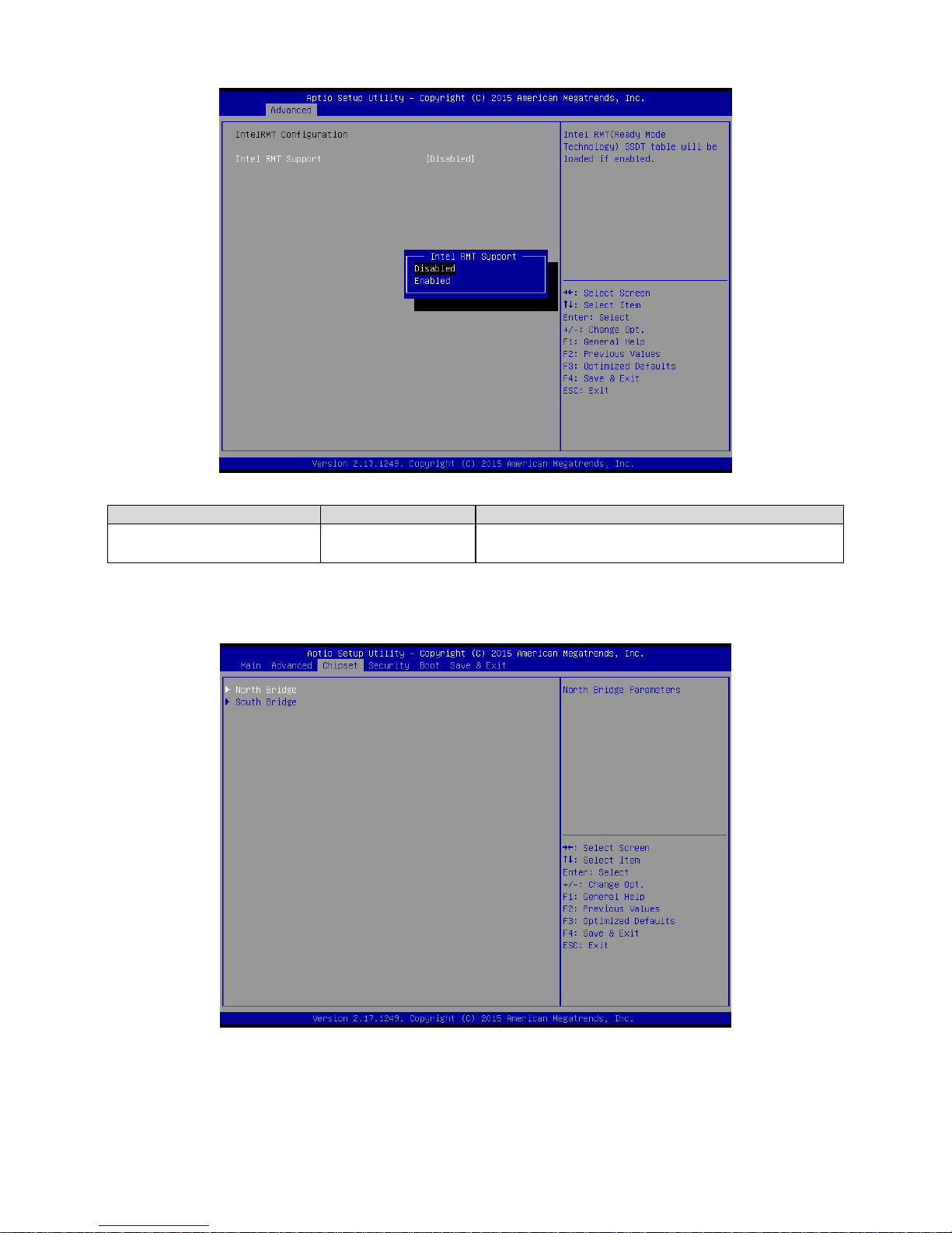
3.6.2.16 IntelRMT Configuration .......................................................................................................... 80
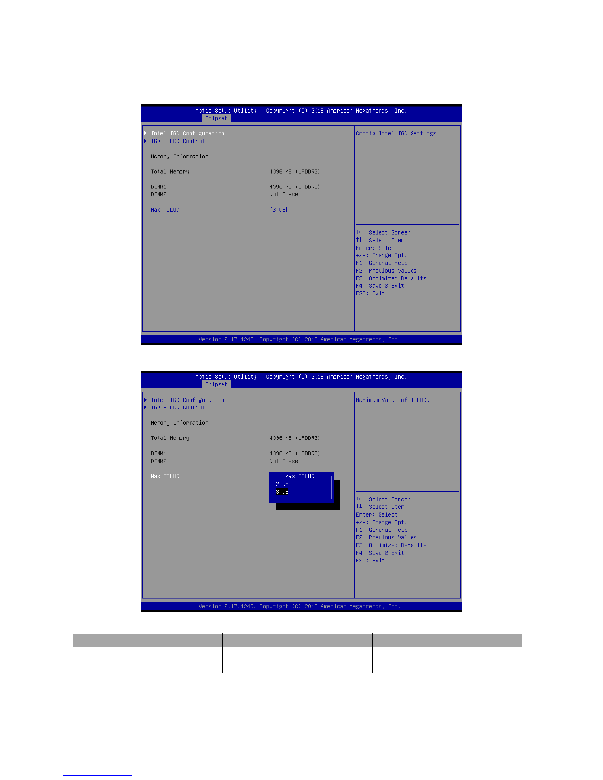
3.6.3 Chipset.......................................................................................................................................... 81
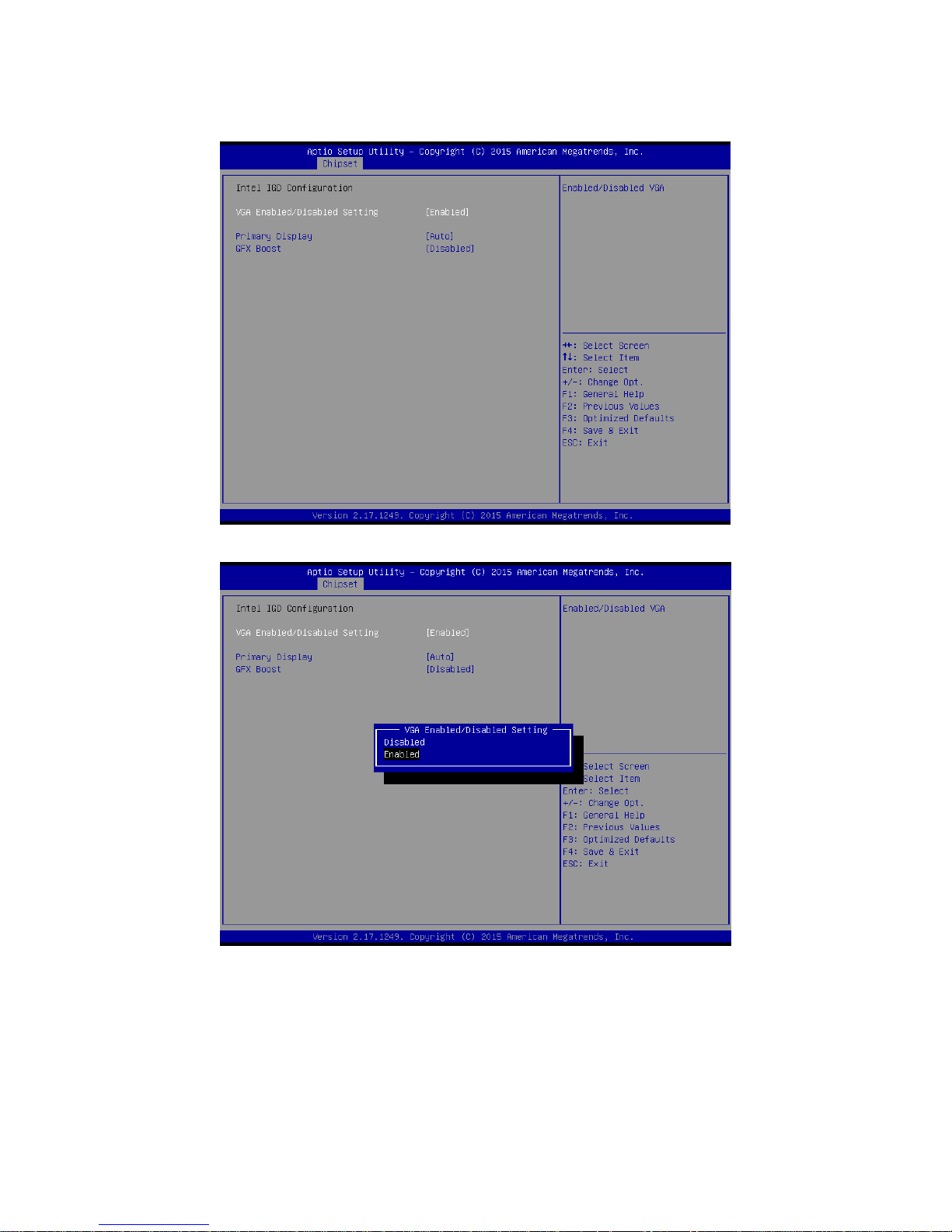
3.6.3.1 North Bridge ........................................................................................................................... 82
Page 7

User’s Manual
EMX-BSWP User’s Manual
7
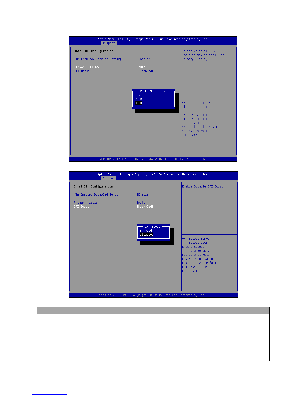
3.6.3.1.1 Intel IGD Configuration .......................................................................................................... 83
3.6.3.1.2 IGD - LCD Control ................................................................................................................. 85
3.6.3.2 South Bridge .......................................................................................................................... 89
3.6.3.2.1 Azalia Configuration .............................................................................................................. 89
3.6.3.2.2 USB Configuration ................................................................................................................. 91
3.6.3.2.3 PCI Express Configuration .................................................................................................... 93
3.6.4 Security ......................................................................................................................................... 97
3.6.4.1 Secure Boot menu ................................................................................................................. 98
3.6.4.1.1 Key Management................................................................................................................... 99
3.6.5 Boot ............................................................................................................................................ 100
3.6.6 Save and exit .............................................................................................................................. 104
4. Drivers Installation..................................................................................................... 106
4.1 Install Chipset Driver ............................................................................................. 107
4.2 Install VGA Driver .................................................................................................. 108
4.3 Install USB3.0 Driver ............................................................................................. 109
4.4 Install Serial IO Driver ........................................................................................... 110
4.5 Install SMSC Hub Driver ....................................................................................... 111
4.6 Install Audio Driver (For Realtek ALC662 HD Audio) ............................................ 112
4.7 Install LAN Driver (For Intel I211AT) ..................................................................... 113
5. Mechanical Drawing .................................................................................................. 115
Page 8
EMX-BSWP User’s Manual
8 EMX-BSWP User’s Manual
1. Getting Started
1.1 Safety Precautions
Warning!
Always completely disconnect the power cord from your
chassis whenever you work with the hardware. Do not
make connections while the power is on. Sensitive
electronic components can be damaged by sudden power
surges. Only experienced electronics personnel should
open the PC chassis.
Caution!
Always ground yourself to remove any static charge before
touching the CPU card. Modern electronic devices are very
sensitive to static electric charges. As a safety precaution,
use a grounding wrist strap at all times. Place all electronic
components in a static-dissipative surface or static-shielded
bag when they are not in the chassis.
1.2 Packing List
Before you begin installing your single board, please make sure that the
following materials have been shipped:
1 x EMX-BSWP motherboard
2 x SATA cables
1 x I/O Shield
1 x SATA Power Cable
Page 9

User’s Manual
EMX-BSWP User’s Manual
9
1.3 Document Amendment History
Revision
Date
By
Comment
1st
January 2016
Avalue
Initial Release
2nd
April 2016
Avalue
Add System Specifications Note
Page 10

EMX-BSWP User’s Manual
10 EMX-BSWP User’s Manual
1.4 Manual Objectives
This manual describes in details Avalue Technology EMX-BSWP Single Board.
We have tried to include as much information as possible but we have not duplicated
information that is provided in the standard IBM Technical References, unless it proved to
be necessary to aid in the understanding of this board.
We strongly recommend that you study this manual carefully before attempting to set up
EMX-BSWP or change the standard configurations. Whilst all the necessary information is
available in this manual we would recommend that unless you are confident, you contact
your supplier for guidance.
Please be aware that it is possible to create configurations within the CMOS RAM that
make booting impossible. If this should happen, clear the CMOS settings, (see the
description of the Jumper Settings for details).
If you have any suggestions or find any errors regarding this manual and want to inform us
of these, please contact our Customer Service department with the relevant details.
Page 11
User’s Manual
EMX-BSWP User’s Manual
11
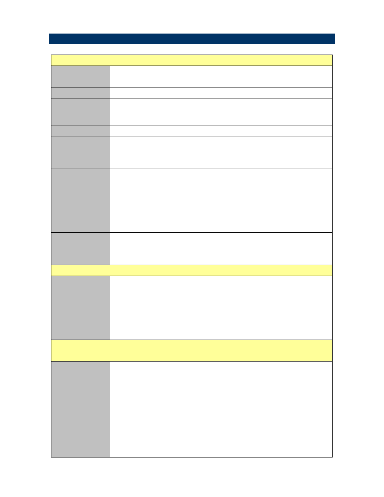
1.5 System Specifications
System
CPU
Intel® Celeron® Processor N3160
(2M Cache, up to 2.24 GHz)
BIOS
AMI uEFI BIOS, 64 Mbit SPI Flash ROM
I/O Chip
EC IT8528E
System Memory
2 x 204-pin DDR3L 1600MHz SODIMMs, up to 8GB
Watchdog Timer
H/W Reset, 1sec. – 65535sec./min.1sec. or 1min. step
H/W Status
Monitor
CPU temperature monitoring
Voltages monitoring
CPU fan speed control
Expansion
1 x full size Mini PCI-e support mSATA (SATA III and mSATA Switchable Through
jumper)
1 x full size Mini PCI-e support WiFi module
1 x SIM card slot
1 x PCI-e x1
1 x SD card slot support SD/ SDHC 3.0 Card
Optional Parts
Optional Infineon SLB9665 support TPM 2.0
Optional eMMC 32GB
S3/S4
Yes (S0/S3/S4/S5)
Display
Resolution
HDMI: 3840 x 2160 @ 30 Hz, 2560 x 1600@ 60 Hz
VGA: 2560 x 1600 @ 60 Hz
2CH 18/24bits LVDS 1920 x 1080
Chrontel. CH7511B eDP to LVDS Converter
HDMI +VGA+LVDS
Triple Display
Internal I/O
Connectors
External I/O
Connector
Storage:
-1 x full size Mini PCI-e support mSATA (SATA III and mSATA Switchable Through
jumper)
- 2 x SATA power connectors
1 x full size Mini PCI-e support WiFi or communication module
1 x PCI-e x1
1 x SIM card Slot
COM:
COM1:
Page 12

EMX-BSWP User’s Manual
12 EMX-BSWP User’s Manual
-COM 1 support RS- RS232/422/485 connector, with / +5V & +12V Supported and
RS422/485 by BIOS setting
1 x 2 x 5 pin, pitch 2.00mm connector for COM1: support RS-232 connector, Pin 9
with / +5V & +12V Supported
1 x 2 x 3 pin, pitch 2.00mm connector for COM1: support RS422/485 connector, Pin
5 with / +5V Supported
COM2~6:
- 5 x 2 x 5 pin, pitch 2.00mm connector for COM2~6: support RS-232 connector,
Pin 9 with / +5V & +12V Supported
2 x 2 x 5 pin, pitch 2.54mm connector for 4 USB 2.0
1 x 2 x 6 pin, pitch 2.00mm connector for GPIO: 8 bits
1 x 2 x 4 pin, pitch 2.00mm connector for BIOS SPI
1 x 2 x 5 pin, pitch 2.00mm connector for EC SPI
1 x 2 x 5 pin, pitch 2.0mm connector for LPC
1 x horizontal type battery connector (Battery cable 170mm length)
1 x 2 x 5 pin, pitch 2.54mm connector for front panel 1
1 x 2 x 5 pin, pitch 2.54mm connector for front panel 2
1 x 2 x 20 pin, pitch 1.25mm connector for LVDS (must be using DF13-2S-1.25C
connector)
1 x 1 x 5 pin, pitch 2.00mm Wafer connector for LCD inverter backlight connector
(5V/12V)
1 x 1 x 3 pin, pitch 2.54mm connector LCD backlight brightness adjustment
(PWM/DC)
1 x 2 x 5 pin, pitch 2.54mm connector for front Audio
1 x 3 pin, pitch 2.54mm connector for S/PDIF
1 x 4 pin, pitch wafer 2.00mm connector for 3W x 2 Speaker
1 x 2 x 5 pin, pitch 2.00mm connector for Keyboard & Mouse
1 x 4 pin, pitch 2.00mm connector for CIR
1 x 3 pin, pitch 2.00mm connector for CMOS clear
1 x 1 x 4 pin, pitch 2.54mm CPU fan connector with smart fan function supported
2 x 1 x 4 pin, pitch 2.00mm connector for LAN Activity Indicator LED
1 x 2 x 2 pin, pitch 4.20mm connector for power input connector
1 x 1 x 3 pin, pitch 2.54mm connector for AT/ATX mode Fanless Operating
Rear I/O
Connectors
Rear Side
External I/O
Connector
2 x RJ-45
1 x VGA
1 x HDMI
1 x Mic-In and 1 x Line-out
1 x DC Jack lockable connector type
Page 13

User’s Manual
EMX-BSWP User’s Manual
13
Mechanical &
Environmental
Power
Requirement
DC in +12V
ACPI
Single power ATX Support S0, S3, S4, S5
ACPI 3.0 Compliant
Power on Type
AT / ATX mode Switchable Through Jumper
Operating Temp.
0 ~ 60°C (32~140°F)
Storage Temp.
-40 ~ +75°C
Operating
Humidity
0%~90% relative humidity, non-condensing
Size (L x W)
6.7" x 6.7" (170mm x 170mm)
Weight
0.40 kg
Note:
1. If user want to install Win 8.1 Pro OS on eMMC of EMX-BSWP motherboard, User must do:
A. BIOS setup menu must select eMMC mode with “PCI mode”(because selection with “ACPI mode” during
OS install, OS cannot find eMMC to install).
B. Windows OS must use Microsoft Win 8.1 Pro with update version of OS image to install.
2. Brightness control method choose ”OS driver”, due to Win7 VGA Driver will cause brightness at 100%,
Backlight adjustment only support to maximum voltage to 2.5V. Therefore, should change item value string as
Image 1, when choose Brightness control method ”OS driver”, please use OS Win8/10.
3. Win7 does not support SD card.
4. When OS is Win7/DOS(default), please choose “Legacy System/Win7” at BIOS setup item. When OS is
Win8/10, please choose “Win8/Win10” at BIOS setup item (Please refer page.65 BOM Config settings.)
5. Specifications are subject to change without notice.
Page 14
EMX-BSWP User’s Manual
14 EMX-BSWP User’s Manual
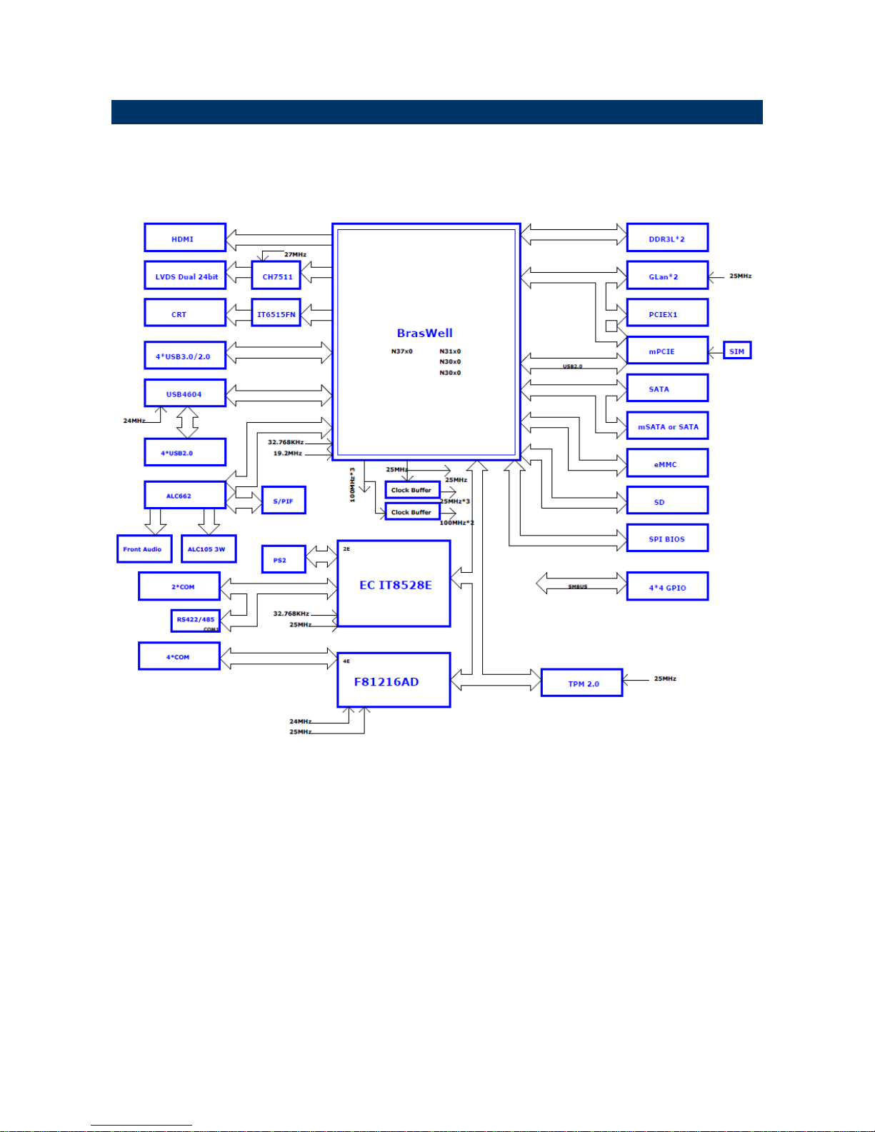
1.6 Architecture Overview—Block Diagram
The following block diagram shows the architecture and main components of EMX-BSWP.
Page 15

User’s Manual
EMX-BSWP User’s Manual
15
2. Hardware
Configuration
Page 16
EMX-BSWP User’s Manual
16 EMX-BSWP User’s Manual
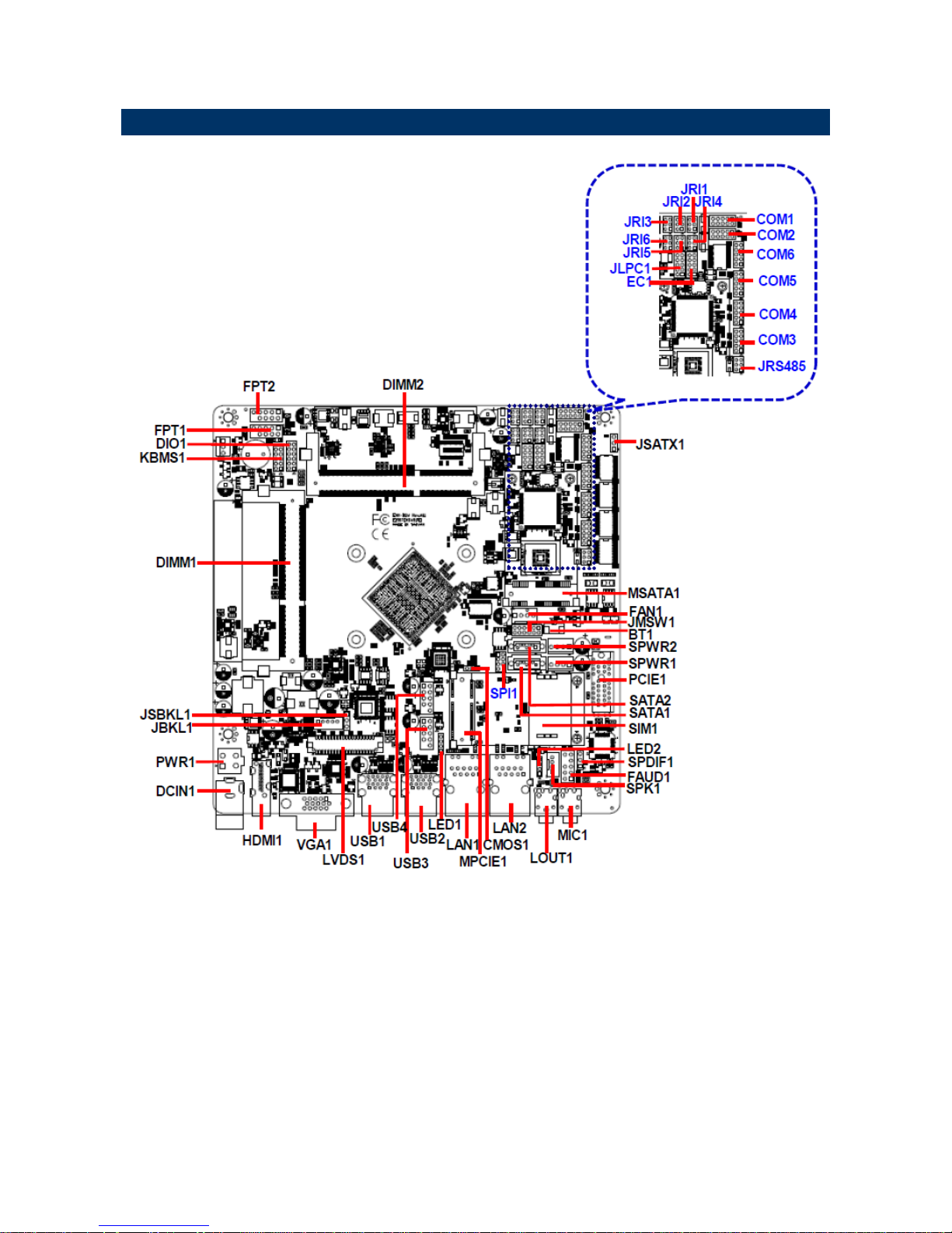
2.1 Product Overview
Page 17
User’s Manual
EMX-BSWP User’s Manual
17
2.2 Jumper and Connector List
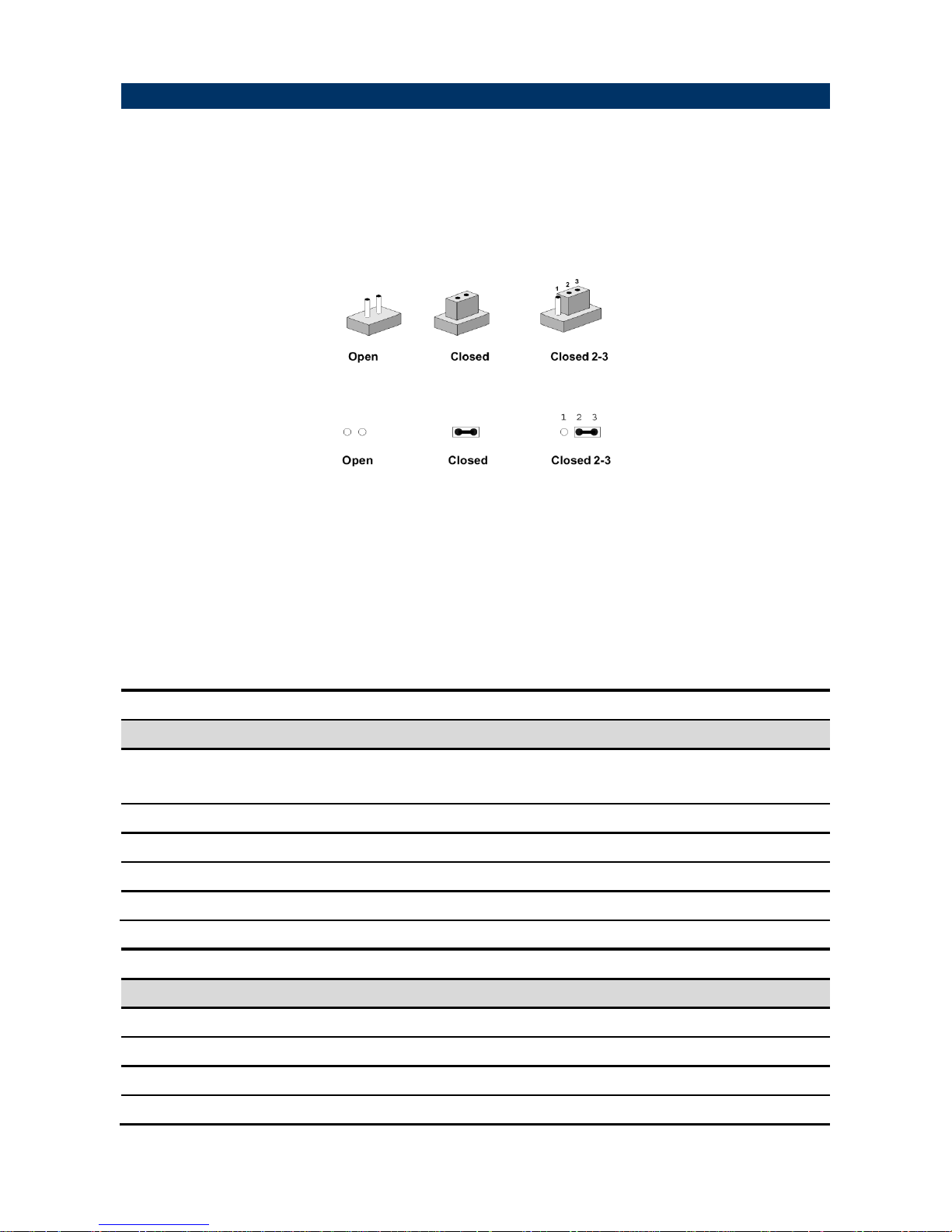
You can configure your board to match the needs of your application by setting jumpers. A
jumper is the simplest kind of electric switch.
It consists of two metal pins and a small metal clip (often protected by a plastic cover) that
slides over the pins to connect them. To “close” a jumper you connect the pins with the clip.
To “open” a jumper you remove the clip. Sometimes a jumper will have three pins, labeled 1,
2, and 3. In this case, you would connect either two pins.
The jumper settings are schematically depicted in this manual as follows:
A pair of needle-nose pliers may be helpful when working with jumpers.
Connectors on the board are linked to external devices such as hard disk drives, a
keyboard, or floppy drives. In addition, the board has a number of jumpers that allow you to
configure your system to suit your application.
If you have any doubts about the best hardware configuration for your application, contact
your local distributor or sales representative before you make any changes.
The following tables list the function of each of the board’s jumpers and connectors.
Jumpers
Label
Function
Note
JRI1/2/3/4/5/6
Serial port 1/2/3/4/5/6 pin9 signal
select
3 x 2 header, pitch 2.00mm
JMSW1
SATA2/MSATA1 mPCIe slot selector
6 x 2 header, pitch 2.00mm
JSBKL1
LVDS Back Light power selection
3 x 1 header, pitch 2.54mm
JSATX1
AT/ATX Power Mode Select
3 x 1 header, pitch 2.54mm
CMOS1
Clear CMOS
3 x 1 header, pitch 2.00mm
Connectors
Label
Function
Note
FAN1
CPU fan connector
4 x 1 wafer, pitch 2.54mm
FPT1
Miscellaneous setting connector 1
5 x 2 header, pitch 2.54 mm
FPT2
Miscellaneous setting connector 2
5 x 2 header, pitch 2.54 mm
DIMM1/2
204-pin DDR3L DIMM socket
Page 18

EMX-BSWP User’s Manual
18 EMX-BSWP User’s Manual
FAUD1
Front Audio connector
5 x 2 header, pitch 2.54 mm
JBKL1
LCD Inverter connector
5 x 1 wafer, pitch 2.00mm
SPI1
SPI connector
4 x 2 header, pitch 2.00mm
COM1
Serial Port 1 connector
5 x 2 header, pitch 2.00mm
COM2
Serial Port 2 connector
5 x 2 header, pitch 2.00mm
COM3
Serial Port 3 connector
5 x 2 header, pitch 2.00mm
COM4
Serial Port 4 connector
5 x 2 header, pitch 2.00mm
COM5
Serial Port 5 connector
5 x 2 header, pitch 2.00mm
COM6
Serial Port 6 connector
5 x 2 header, pitch 2.00mm
DIO1
General purpose I/O connector
6 x 2 header, pitch 2.00mm
SPK1
Speaker connector
1 x 4 wafer, pitch 2.00 mm
LVDS1
LVDS Connector
DIN 40-pin wafer, pitch 1.25mm
USB1/2
USB connector 1/2
USB3/4
USB connector 3/4
5 x 2 header, pitch 2.54mm
SPDIF1
Sony/Philips Digital Interface
3 x 1 header, pitch 2.54 mm
LAN1/2
RJ-45 Ethernet 1/2
PCIE1
PCIe connector
LED1
LED indicator connector 1
4 x 1 header, pitch 2.00mm
LED2
LED indicator connector 2
4 x 1 header, pitch 2.00mm
KBMS1
PS/2 keyboard & mouse connector
5 x 2 header, pitch 2.00 mm
BT1
Battery connector
2 x 1 wafer, pitch 1.25mm
MSATA1
Full size mPCIe Slot
MPCIE1
Mini-PCIe connector 1
JRS485
Serial Port 1 RS485/422 Mode
connector
3 x 2 header, pitch 2.00 mm
JLPC1
LPC connector
5 x 2 header, pitch 2.00mm
PWR1
Power connector
2 x 2 wafer, pitch 4.20mm
SATA1/2
Serial ATA connector 1/2
SPWR1/2
SATA Power connector 1/2
4 x 1 wafer, pitch 2.54mm
EC1
EC_Program
5 x 2 header, pitch 2.00 mm
DCIN1
DC Power-in connector
SIM1
SIM card slot
HDMI1
HDMI connector
LOUT1
Line-out audio jack
MIC1
Mic-in audio jack
VGA1
VGA connector
Page 19
User’s Manual
EMX-BSWP User’s Manual
19
2.3 Setting Jumpers & Connectors
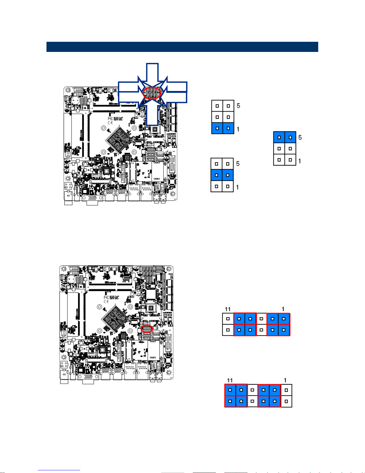
2.3.1 Serial port 1/2/3/4/5/6 pin9 signal select (JRI1/JRI2/JRI3/JRI4/JRI5/JRI6)
* Default
Ring*
+5V
+12V
2.3.2 SATA2/MSATA1 mPCIe slot selector (JMSW1)
* Default
Note:
SATA2/MSATA1 shared SATA signal, can not be used
simultaneously.
SATA2 Connector *
(SATA2 Connector enabled, MSATA1 slot Disabled)
MSATA1 mPCIe slot
(MSATA1 slot enabled, SATA2 Connector Disabled)
JRI4
JRI6
JRI5
JRI2
Page 20
EMX-BSWP User’s Manual
20 EMX-BSWP User’s Manual
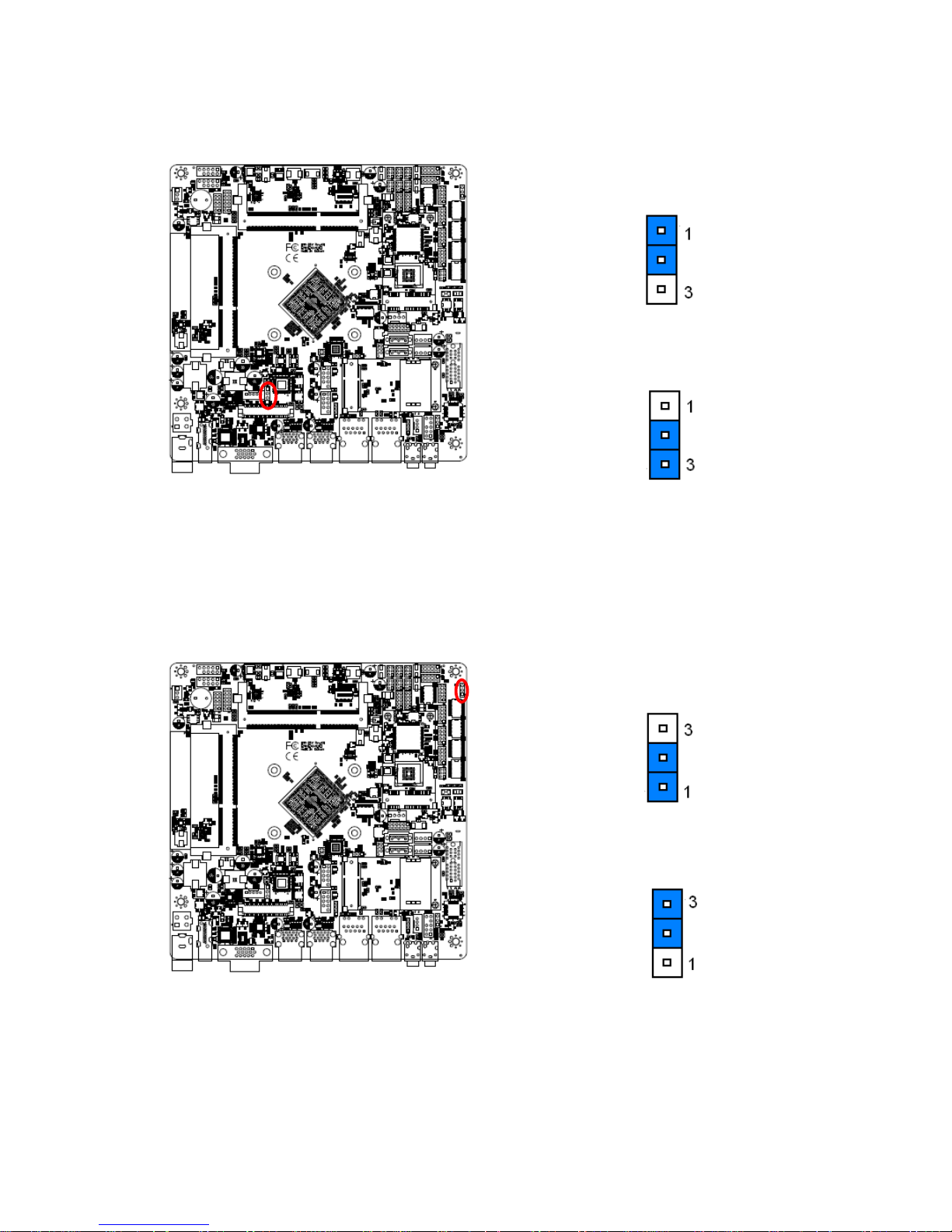
2.3.3 LVDS Back Light power selection (JSBKL1)
* Default
PWM Mode*(Max current: 2A)
DC Mode(Max current: 2A)
2.3.4 AT/ATX Power Mode Select (JSATX1)
* Default
ATX*
AT
Page 21
User’s Manual
EMX-BSWP User’s Manual
21
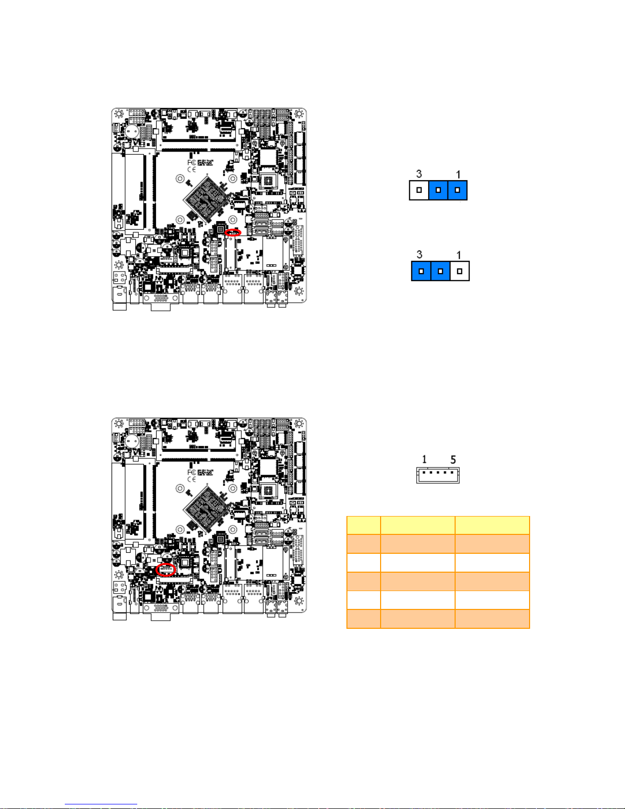
2.3.5 Clear CMOS (CMOS1)
* Default
Protect*
Clear CMOS
2.3.6 LCD Inverter connector (JBKL1)
PIN
Signal
Max current
1
+12V
2A
2
GND
3
LVDS_BKLTEN
4
LVDS_BKLADJ
5
+5V
2A
Page 22
EMX-BSWP User’s Manual
22 EMX-BSWP User’s Manual
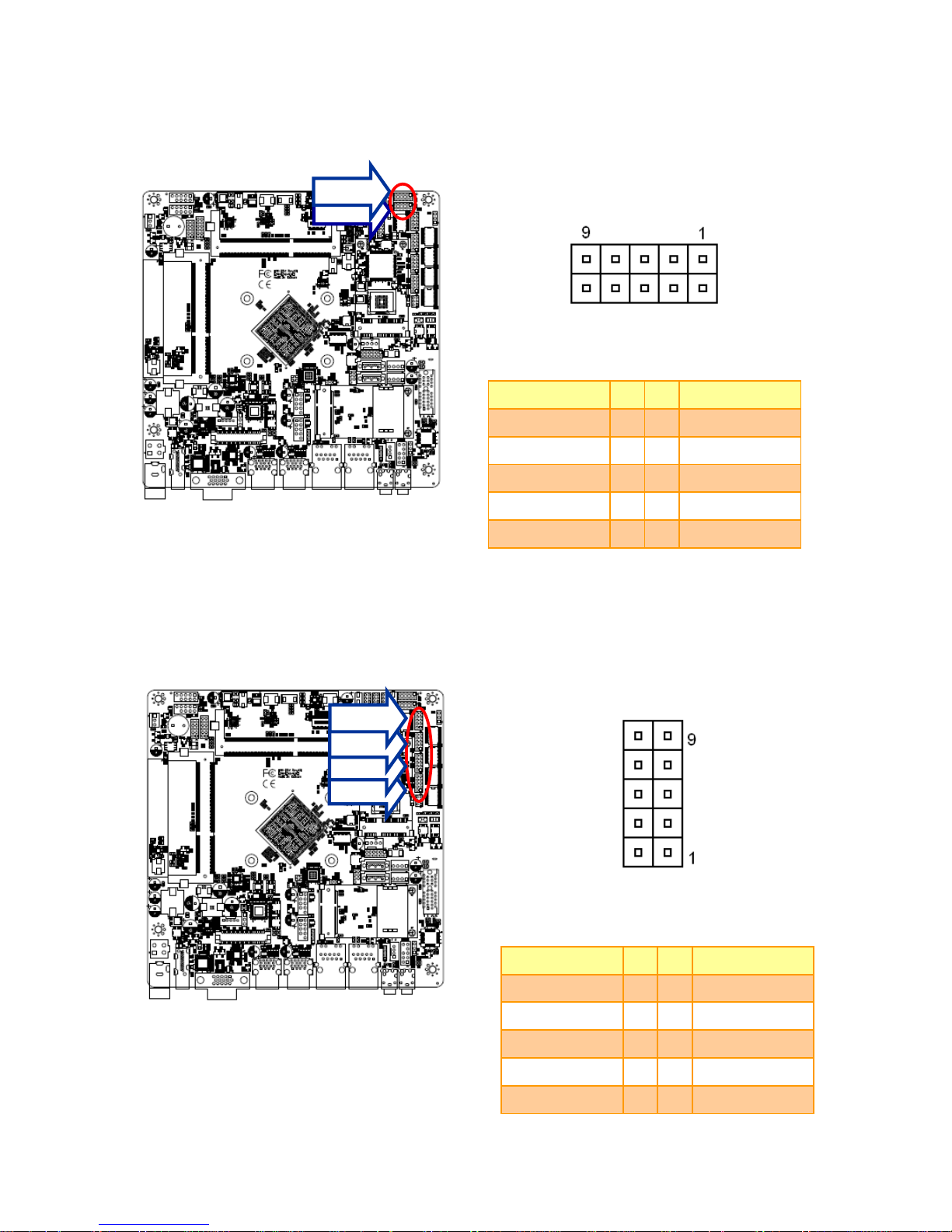
2.3.7 Serial port 1/2 connector (COM1/2)
Signal
PIN
PIN
Signal
NDCD #
1 2 NRXD
NTXD
3 4 NDTR#
GND
5 6 NDSR#
NRTS #
7 8 NCTS#
NRI#
9
10
NC
2.3.8 Serial port 3/4/5/6 connector (COM3/4/5/6)
Signal
PIN
PIN
Signal
NC
10 9 NRI#
NCTS#
8 7 NRTS#
NDSR#
6 5 GND
NDTR#
4 3 NTXD
NRXD
2 1 NDCD#
COM2
COM1
COM3
COM4
COM5
COM6
Page 23
User’s Manual
EMX-BSWP User’s Manual
23
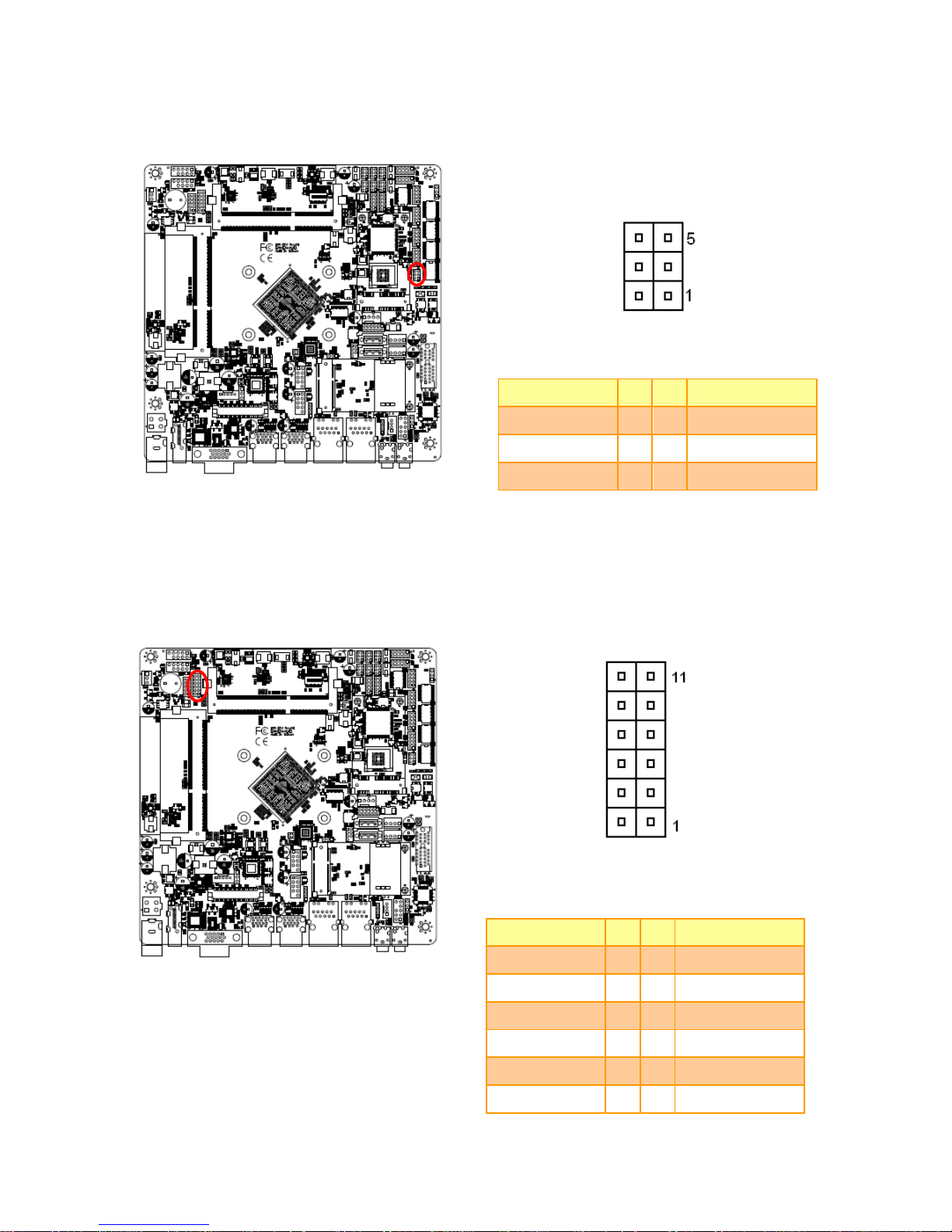
2.3.9 Serial Port 1 RS485/422 Mode connector (JRS485)
Signal
PIN
PIN
Signal
GND
6 5 +5V
422RX+
4 3 485TX+
422RX-
2 1 485TX-
2.3.10 General purpose I/O connector (DIO1)
Signal
PIN
PIN
Signal
+5V
12
11
GND
SMB_DATA
10 9 SMB_CLK
DO3
8 7 DI3
DO2
6 5 DI2
DO1
4 3 DI1
DO0
2 1 DI0
Page 24
EMX-BSWP User’s Manual
24 EMX-BSWP User’s Manual
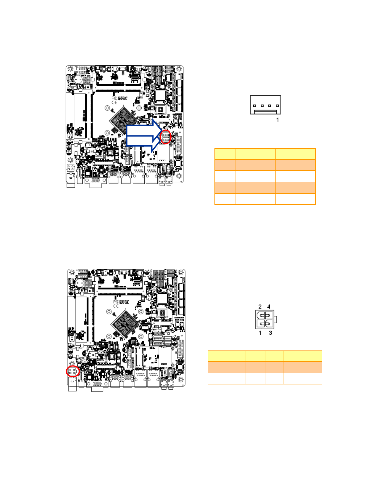
2.3.11 SATA Power connector 1/2 (SPWR1/2)
PIN
Signal
Max current
1
+V5S_SATA
3A
2
GND
3
GND
4
+V12S_SATA
3A
2.3.12 Power connector (PWR1)
Signal
PIN
PIN
Signal
GND
1
2
GND
+VIN_12V
3 4 +VIN_12V
SPWR1
SPWR2
Page 25
User’s Manual
EMX-BSWP User’s Manual
25
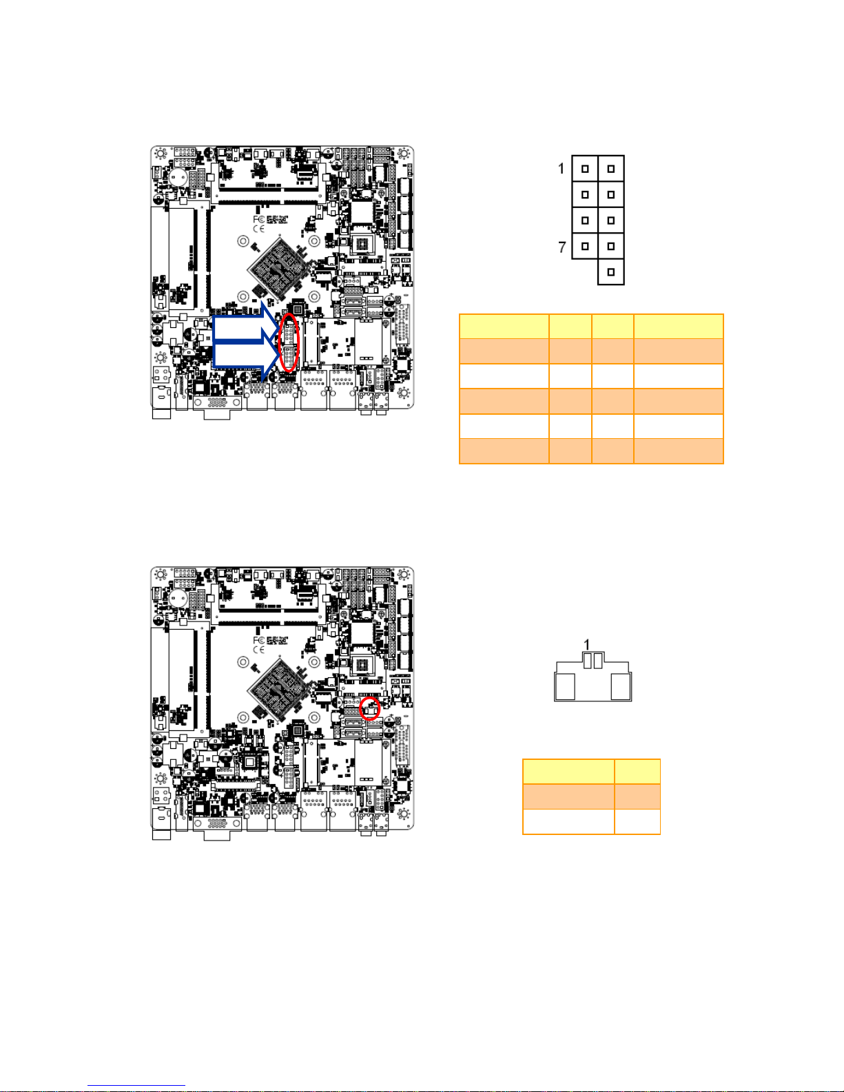
2.3.13 USB connector 3/4 (USB3/4)
Signal
PIN
PIN
Signal
+V5A_USB01
1
2
+V5A_USB01
USB_DN0
3 4 USB_DN1
USB_DP0
5
6
USB_DP1
GND
7 8 GND
10
NC
2.3.14 Battery connector (BT1)
Signal
PIN
+3V
1
GND
2
USB4
USB3
Page 26
EMX-BSWP User’s Manual
26 EMX-BSWP User’s Manual
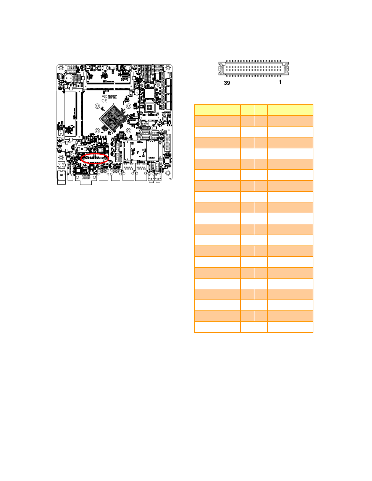
2.3.15 LVDS connector (LVDS1)
Signal
PIN
PIN
Signal
+5V
2 1 +3.3V
+5V
4 3 +3.3V
EDP_DDC_DAT
6 5 EDP_DDC_SCL
GND
8 7 GND
LVDS_DATAP0
10 9 LVDS_DATAP1
LVDS_DATAN0
12
11
LVDS_DATAN1
GND
14
13
GND
LVDS_DATAP2
16
15
LVDS_DATAP3
LVDS_DATAN2
18
17
LVDS_DATAN3
GND
20
19
GND
LVDS_DATAP4
22
21
LVDS_DATAP5
LVDS_DATAN4
24
23
LVDS_DATAN5
GND
26
25
GND
LVDS_DATAP6
28
27
LVDS_DATAP7
LVDS_DATAN6
30
29
LVDS_DATAN7
GND
32
31
GND
LVDS_CLK1P
34
33
LVDS_CLK2P
LVDS_ CLK1N
36
35
LVDS_ CLK2N
GND
38
37
GND
+12V
40
39
+12V
Page 27
User’s Manual
EMX-BSWP User’s Manual
27
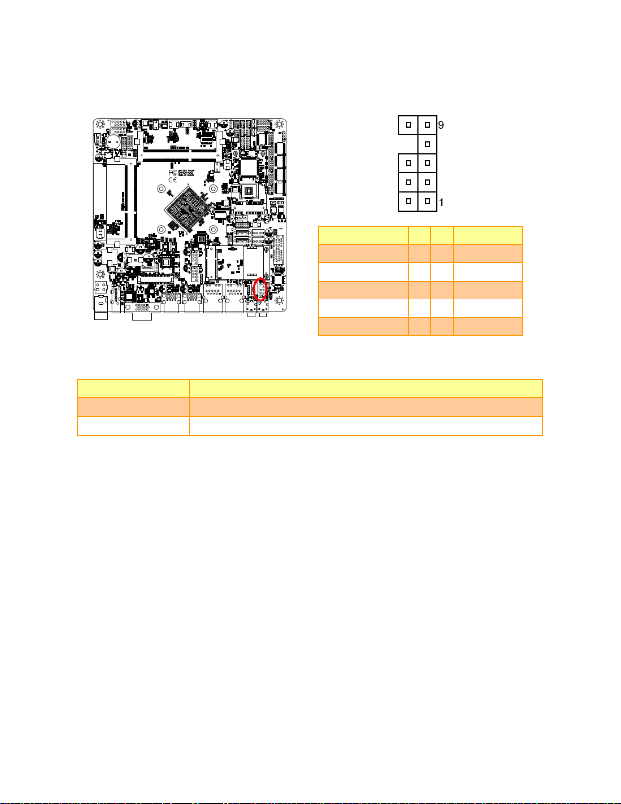
2.3.16 Audio connector (FAUD1)
Signal
PIN
PIN
Signal
LINE2_JD
10 9 LINE2_L
7 SENSE_B
MIC2_JD
6 5 LINE2_R
AUD_FRONT_DET
4 3 MIC2_R
GND
2 1 MIC2_L
2.3.16.1 Signal Description –Front Audio connector (FAUD1)
Signal
Signal Description
LINE2_JD
AUDIO IN (LINE_RIN/LIN)sense pin
MIC2_JD
MIC IN (MIC_RIN/LIN) sense pin
Page 28
EMX-BSWP User’s Manual
28 EMX-BSWP User’s Manual
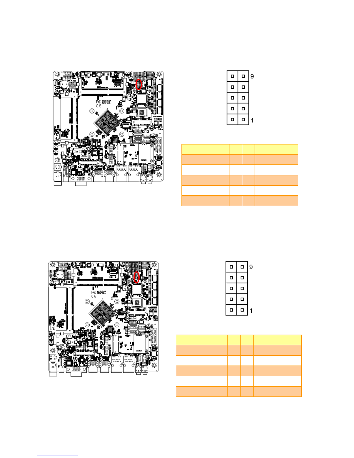
2.3.17 LPC connector (JLPC1)
Signal
PIN
PIN
Signal
GND
10 9 LPC_SERIRQ
LPC_DEG_CLK
8 7 LPC_AD3
LPC_FRAME#
6 5 LPC_AD2
PLT_RST#
4 3 LPC_AD1
+3.3V
2 1 LPC_AD0
2.3.18 EC_Program (EC1)
Signal
PIN
PIN
Signal
EC_SMDATA_DBG
10 9 EC_SMCLK_DBG
NC
8 7 EC_HOLD#
EC_FSMOSI
6 5 EC_FSMIOSO
EC_FSCK
4 3 EC_FSCE#
GND
2 1 +3.3A_ECSPI
Page 29
User’s Manual
EMX-BSWP User’s Manual
29
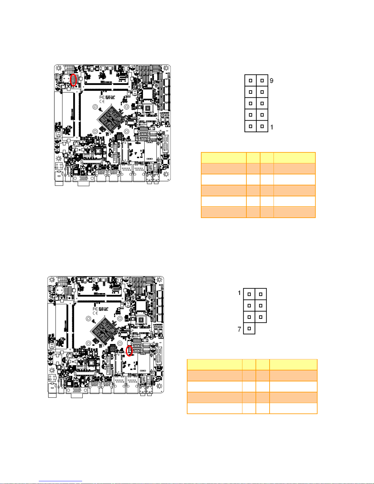
2.3.19 PS/2 keyboard & mouse connector (KBMS1)
Signal
PIN
PIN
Signal
NC
10 9 NC
NC
8 7 NC
MSCK
6 5 MSDAT
+5VSB
4 3 GND
KBCK
2 1 KBDAT
2.3.20 SPI connector (SPI1)
Signal
PIN
PIN
Signal
+VSPI_BIOS
1 2 GND
SPI_CS0#
3 4 SPI_CLK
SPI_MISO
5 6 SPI_MOSI
SPI_HOLD#
7
Page 30
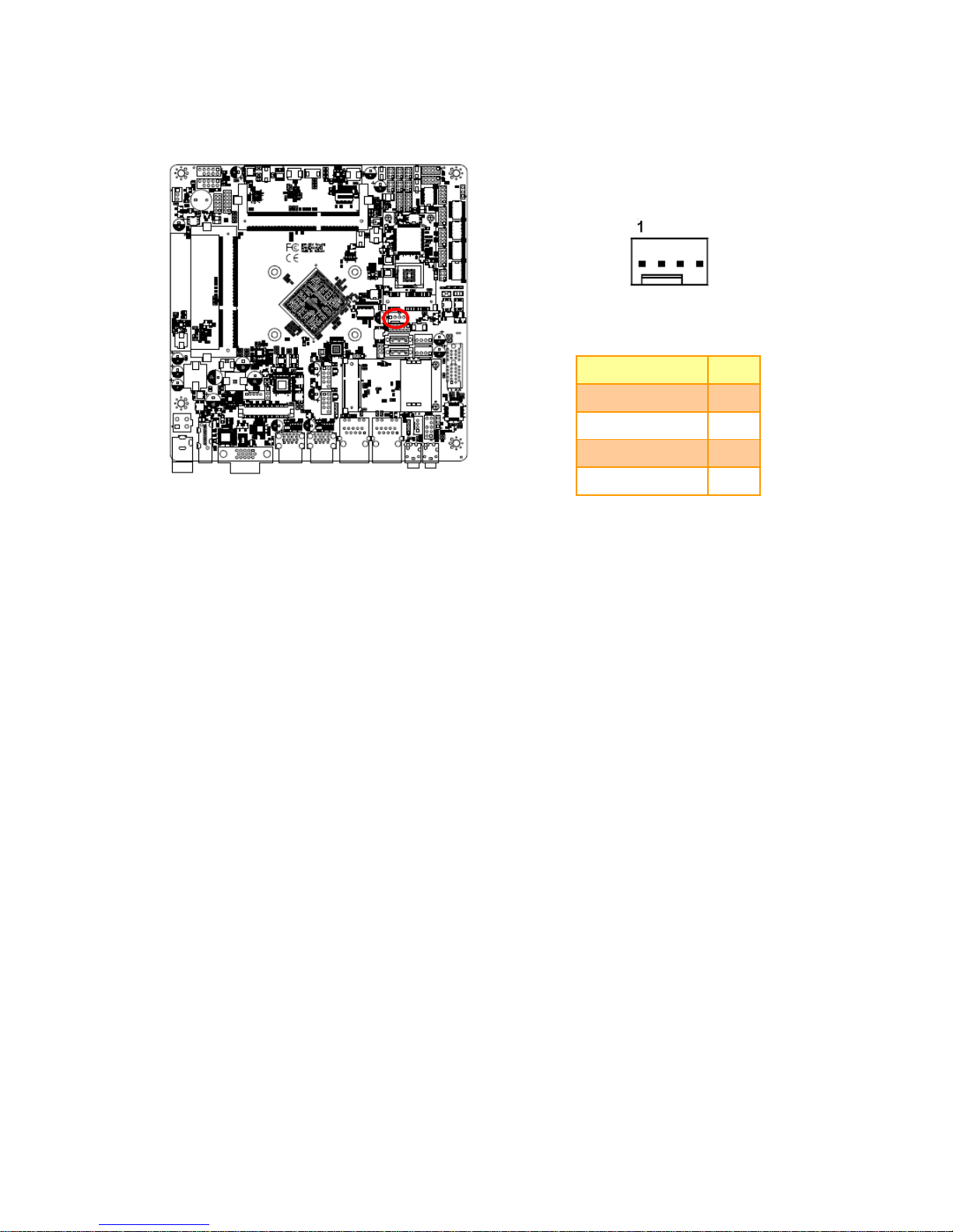
EMX-BSWP User’s Manual
30 EMX-BSWP User’s Manual
2.3.21 Sony/Philips Digital Interface (SPDIF1)
Signal
PIN
GND
3
SPDIF_OUT
2
+5V
1
2.3.22 Speaker connector (SPK1)
Signal
PIN
RSPK-
4
RSPK+
3
LSPK-
2
LSPK+
1
Page 31
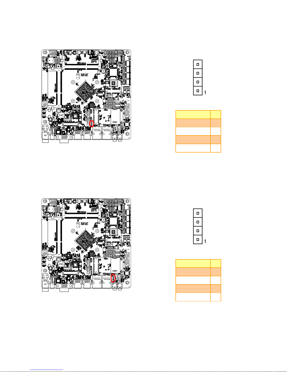
User’s Manual
EMX-BSWP User’s Manual
31
2.3.23 Miscellaneous setting connector 1 (FPT1)
Signal
PIN
PIN
Signal
+HD_LED
1 2 +PWR_LED
-HD_LED
3 4 -PWE_LED
+Reset
5 6 +PWR_BNT
-Reset
7 8 -PWR_BNT
NC
9
2.3.24 Miscellaneous setting connector 2 (FPT2)
Signal
PIN
PIN
Signal
Speaker+
1 2 BLK_VR(10K)
NC
3 4 BLK_UP
NC
5 6 BLK_DN
Speaker-
7 8 GND
GND
9
10
Note:
1. Pin2 with GND: Control LVDS Backlight by use Variable Resistor.
2. BLK_UP with GND/BLK_DN with GND: Step control LVDS Backlight by use button and BIOS must to be
set “BR Button”. (Please refer to page.88)
Page 32
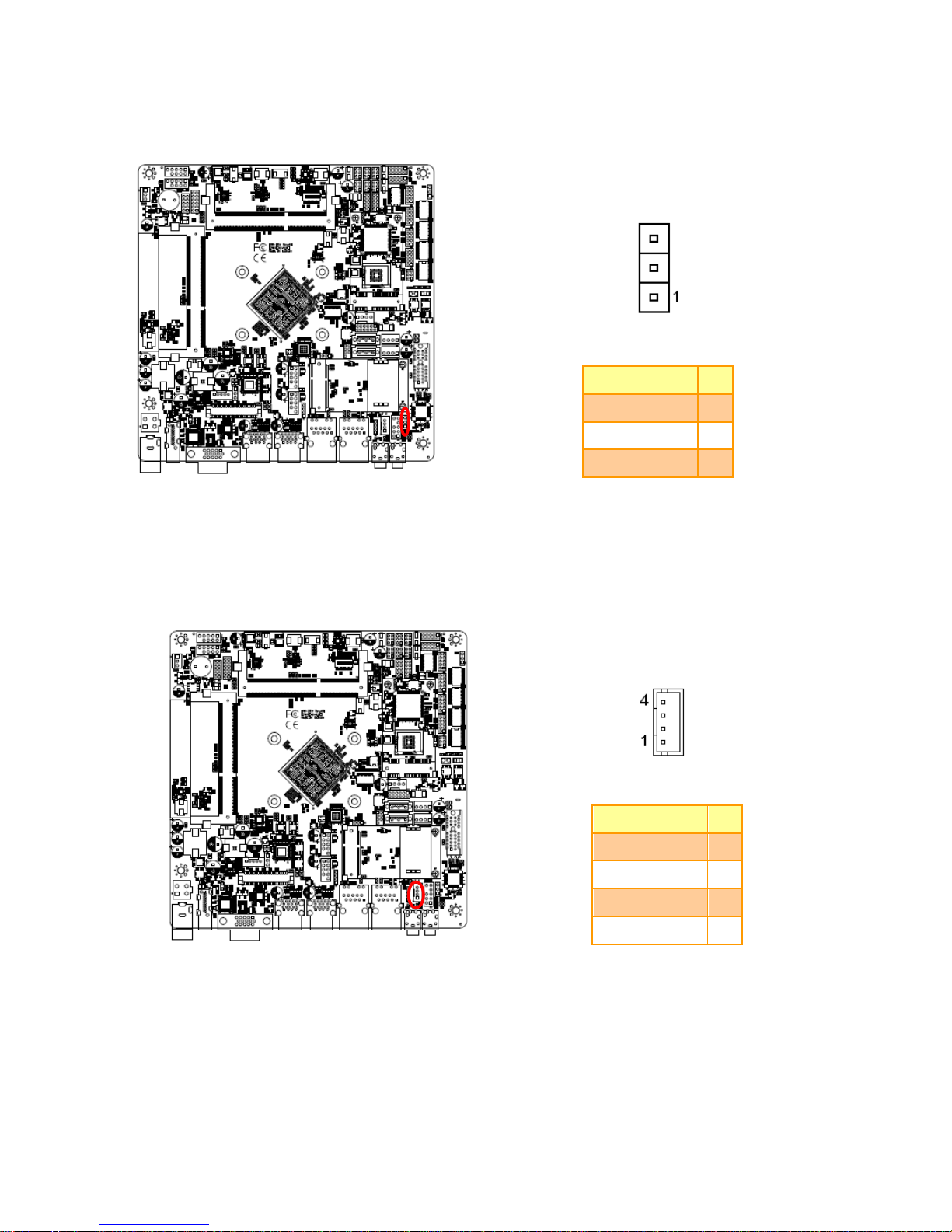
EMX-BSWP User’s Manual
32 EMX-BSWP User’s Manual
2.3.25 LED indicator connector 1 (LED1)
Signal
PIN
L1_1000#_LED
4
L1_100#_LED
3
L1_ACT_N
2
L1_ACT_P
1
2.3.26 LED indicator connector 2 (LED2)
Signal
PIN
L2_1000#_LED
4
L2_100#_LED
3
L2_ACT_N
2
L2_ACT_P
1
Page 33
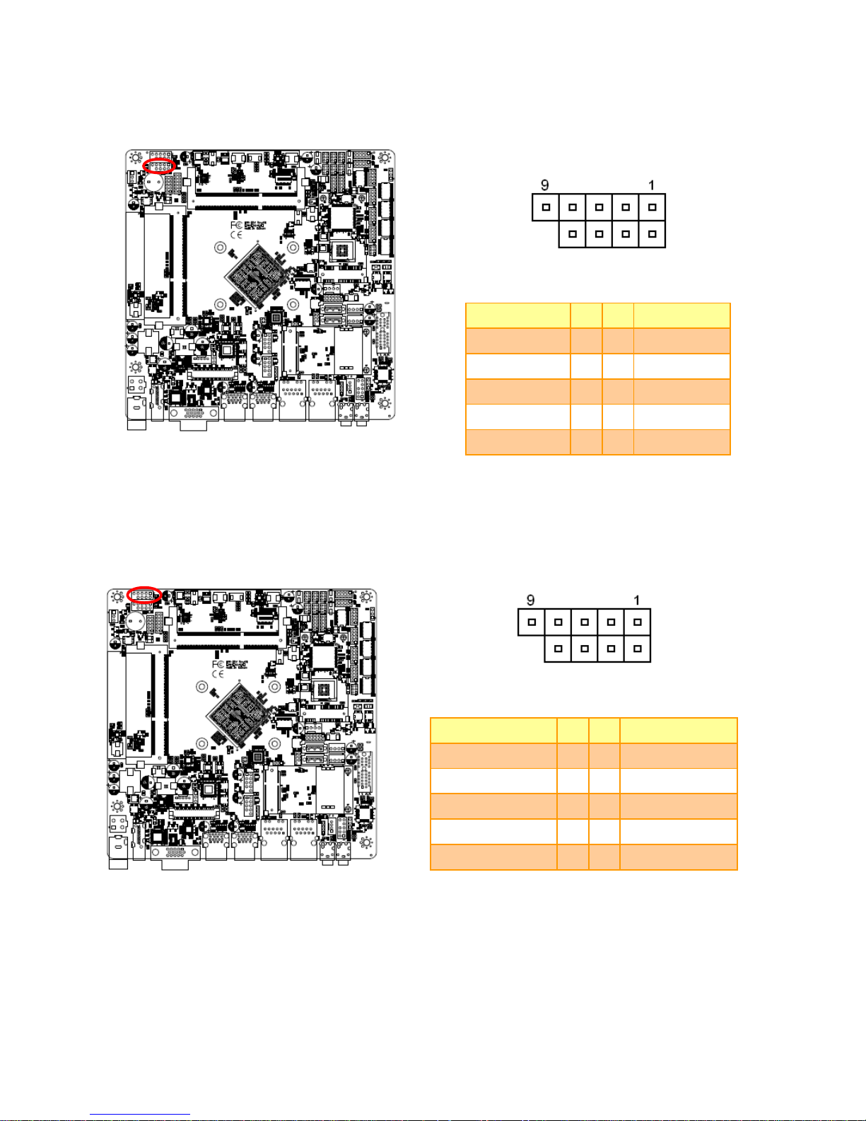
User’s Manual
EMX-BSWP User’s Manual
33
2.3.27 CPU fan connector (FAN1)
Signal
PIN
GND
1
+12V
2
CPU_FANIN
3
CPU_FANOUT
4
Page 34

EMX-BSWP User’s Manual
34 EMX-BSWP User’s Manual
3.BIOS Setup
Page 35

User’s Manual
EMX-BSWP User’s Manual
35
3.1 Introduction
The BIOS setup program allows users to modify the basic system configuration. In this
following chapter will describe how to access the BIOS setup program and the
configuration options that may be changed.
3.2 Starting Setup
The AMI BIOS™ is immediately activated when you first power on the computer. The BIOS
reads the system information contained in the NVRAM and begins the process of checking
out the system and configuring it. When it finishes, the BIOS will seek an operating system
on one of the disks and then launch and turn control over to the operating system.
While the BIOS is in control, the Setup program can be activated in one of two ways:
By pressing <Del> or <F2> immediately after switching the system on, or
By pressing the <Del> or <F2> key when the following message appears briefly at the
left-top of the screen during the POST (Power On Self Test).
Press <Del> or <F2> to enter SETUP
If the message disappears before you respond and you still wish to enter Setup, restart the
system to try again by turning it OFF then ON or pressing the "RESET" button on the
system case. You may also restart by simultaneously pressing <Ctrl>, <Alt>, and <Delete>
keys. If you do not press the keys at the correct time and the system does not boot, an error
message will be displayed and you will again be asked to.
Press F1 to Continue, DEL to enter SETUP
Page 36

EMX-BSWP User’s Manual
36 EMX-BSWP User’s Manual
3.3 Using Setup
In general, you use the arrow keys to highlight items, press <Enter> to select, use the
PageUp and PageDown keys to change entries, press <F1> for help and press <Esc> to
quit. The following table provides more detail about how to navigate in the Setup program
using the keyboard.
Button
Description
↑
Move to previous item
↓
Move to next item
←
Move to the item in the left hand
→
Move to the item in the right hand
Esc key
Main Menu -- Quit and not save changes into NVRAM
Status Page Setup Menu and Option Page Setup Menu -- Exit current page and
return to Main Menu
+ key
Increase the numeric value or make changes
- key
Decrease the numeric value or make changes
F1 key
General help, only for Status Page Setup Menu and Option Page Setup Menu
F2 key
Previous Values.
F3 key
Optimized defaults
F4 key
Save & Exit Setup
Navigating Through The Menu Bar
Use the left and right arrow keys to choose the menu you want to be in.
Note: Some of the navigation keys differ from one screen to another.
To Display a Sub Menu
Use the arrow keys to move the cursor to the sub menu you want. Then press
<Enter>. A “” pointer marks all sub menus.
Page 37

User’s Manual
EMX-BSWP User’s Manual
37
3.4 Getting Help
Press F1 to pop up a small help window that describes the appropriate keys to use and the
possible selections for the highlighted item. To exit the Help Window press <Esc> or the F1
key again.
3.5 In Case of Problems
If, after making and saving system changes with Setup, you discover that your computer no
longer is able to boot, the AMI BIOS supports an override to the NVRAM settings which
resets your system to its defaults.
The best advice is to only alter settings which you thoroughly understand. To this end, we
strongly recommend that you avoid making any changes to the chipset defaults. These
defaults have been carefully chosen by both BIOS Vendor and your systems manufacturer
to provide the absolute maximum performance and reliability. Even a seemingly small
change to the chipset setup has the potential for causing you to use the override.
Page 38
EMX-BSWP User’s Manual
38 EMX-BSWP User’s Manual
3.6 BIOS setup
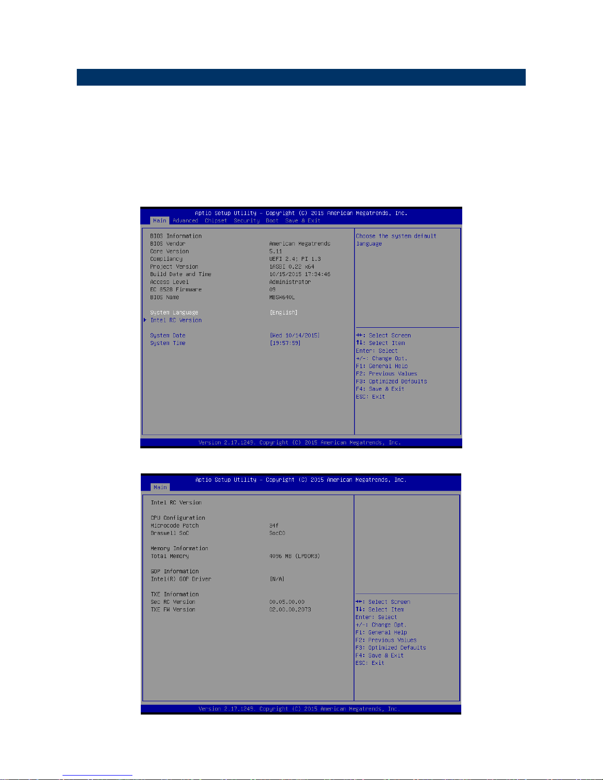
Once you enter the Aptio Setup Utility, the Main Menu will appear on the screen. The Main
Menu allows you to select from several setup functions and exit choices. Use the arrow
keys to select among the items and press <Enter> to accept and enter the sub-menu.
3.6.1 Main Menu
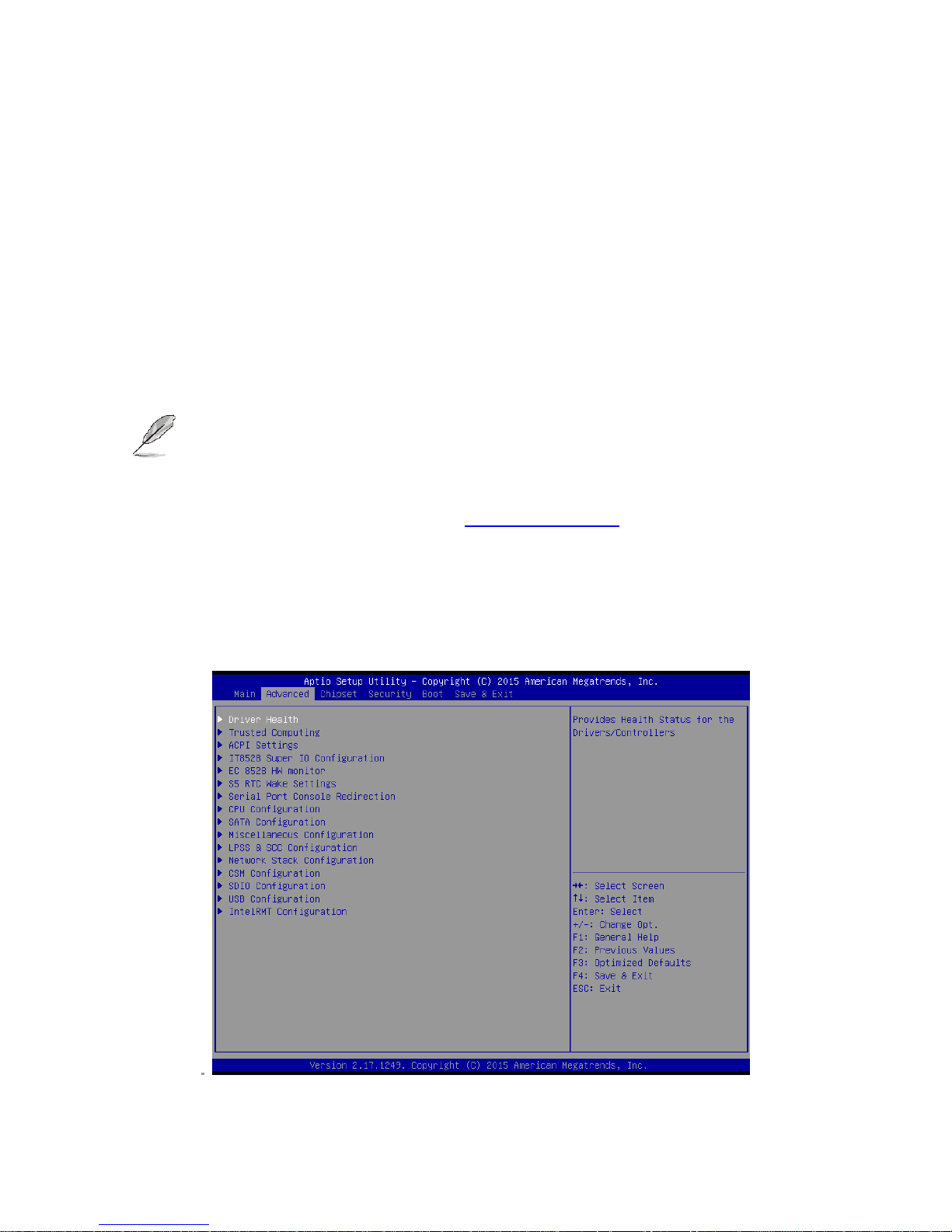
This section allows you to record some basic hardware configurations in your computer and
set the system clock.
Page 39
User’s Manual
EMX-BSWP User’s Manual
39
3.6.1.1 System Language
This option allows choosing the system default language.
3.6.1.2 System Date
Use the system date option to set the system date. Manually enter the day, month and
year.
3.6.1.3 System Time
Use the system time option to set the system time. Manually enter the hours, minutes and
seconds.
Note: The BIOS setup screens shown in this chapter are for reference purposes
only, and may not exactly match what you see on your screen.
Visit the Avalue website (www.avalue.com.tw) to download the latest
product and BIOS information.
3.6.2 Advanced Menu
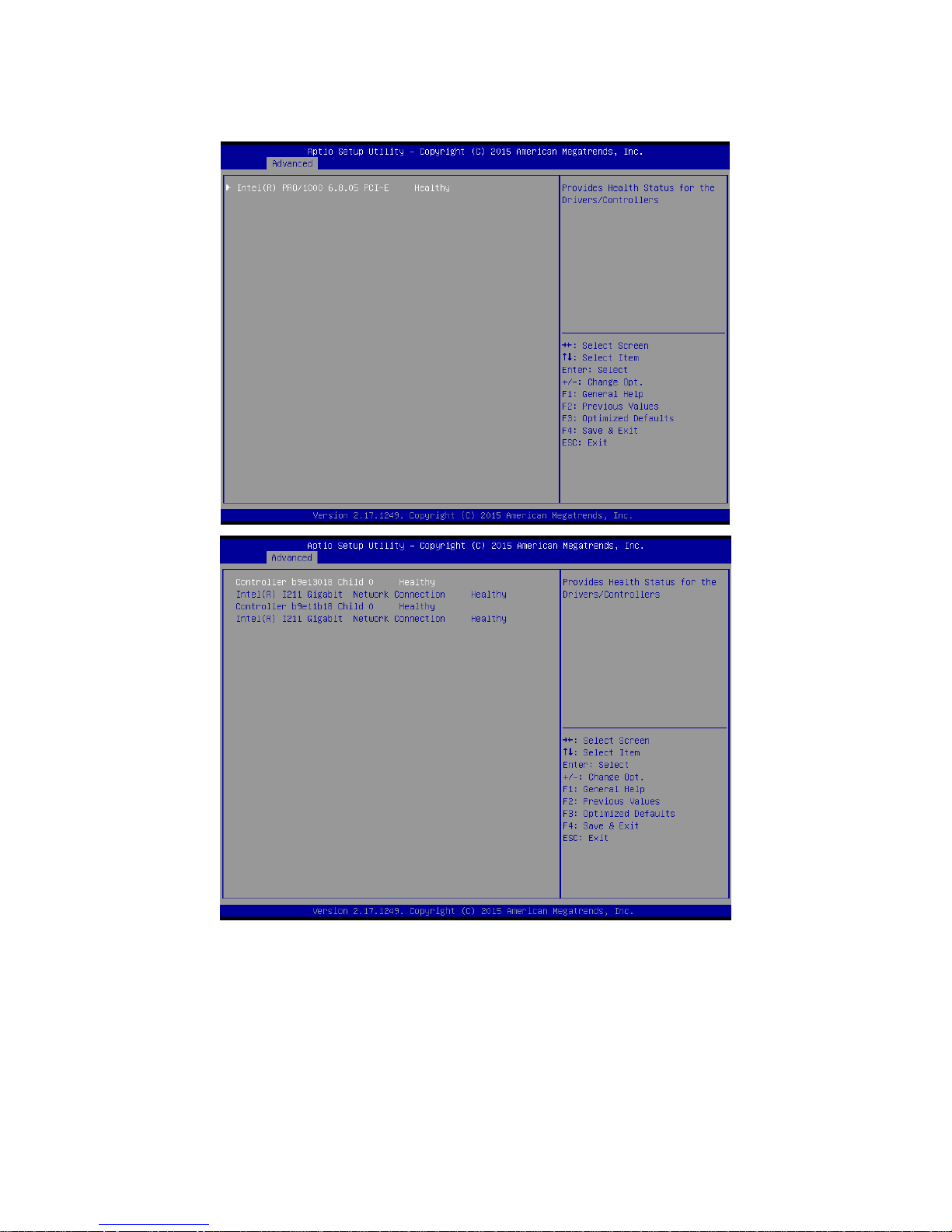
This section allows you to configure your CPU and other system devices for basic operation
through the following sub-menus.
Page 40
EMX-BSWP User’s Manual
40 EMX-BSWP User’s Manual
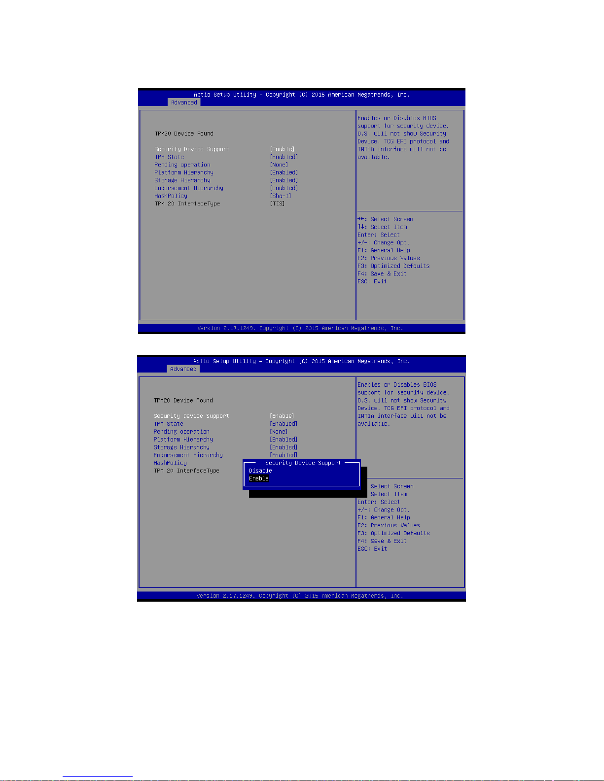
3.6.2.1 Driver Health
Page 41
User’s Manual
EMX-BSWP User’s Manual
41
3.6.2.2 Trusted Computing
Page 42
EMX-BSWP User’s Manual
42 EMX-BSWP User’s Manual
Page 43
User’s Manual
EMX-BSWP User’s Manual
43
Page 44
EMX-BSWP User’s Manual
44 EMX-BSWP User’s Manual
Item
Options
Description
Security Device Support
Disable,
Enable[Default]
Enables or Disables BIOS support for security
device. O.S. will not show Security Device. TCG EFI
protocol and INT1Ainterface will not be available.
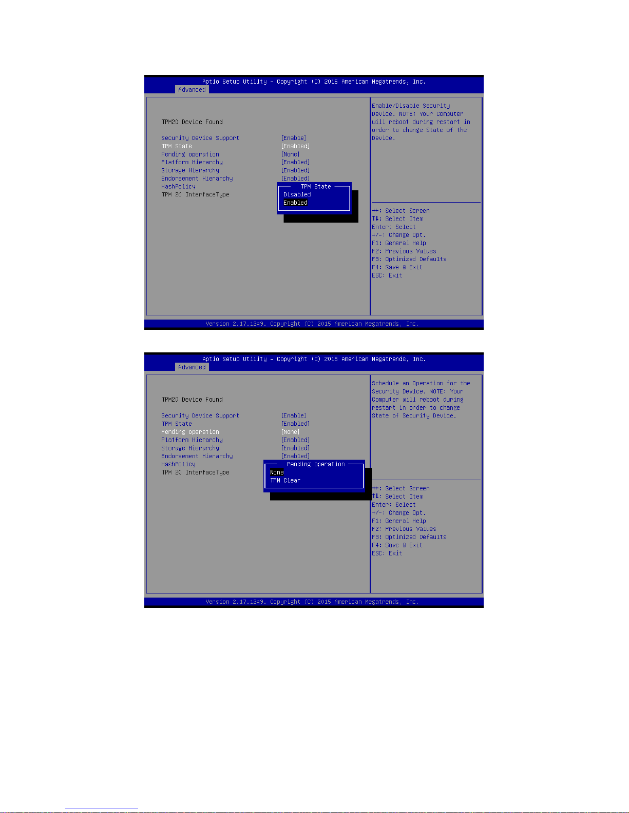
TPM State
Disabled,
Enabled[Default]
Enable/Disable Security Device. NOTE: Your
Computer will reboot during restart in order to
Page 45
User’s Manual
EMX-BSWP User’s Manual
45
change State of the Device.
Pending operation
None[Default]
TPM Clear
Schedule an Operation for the Security Device.
NOTE: Your Computer will reboot during restart in
order to change State of Security Device.
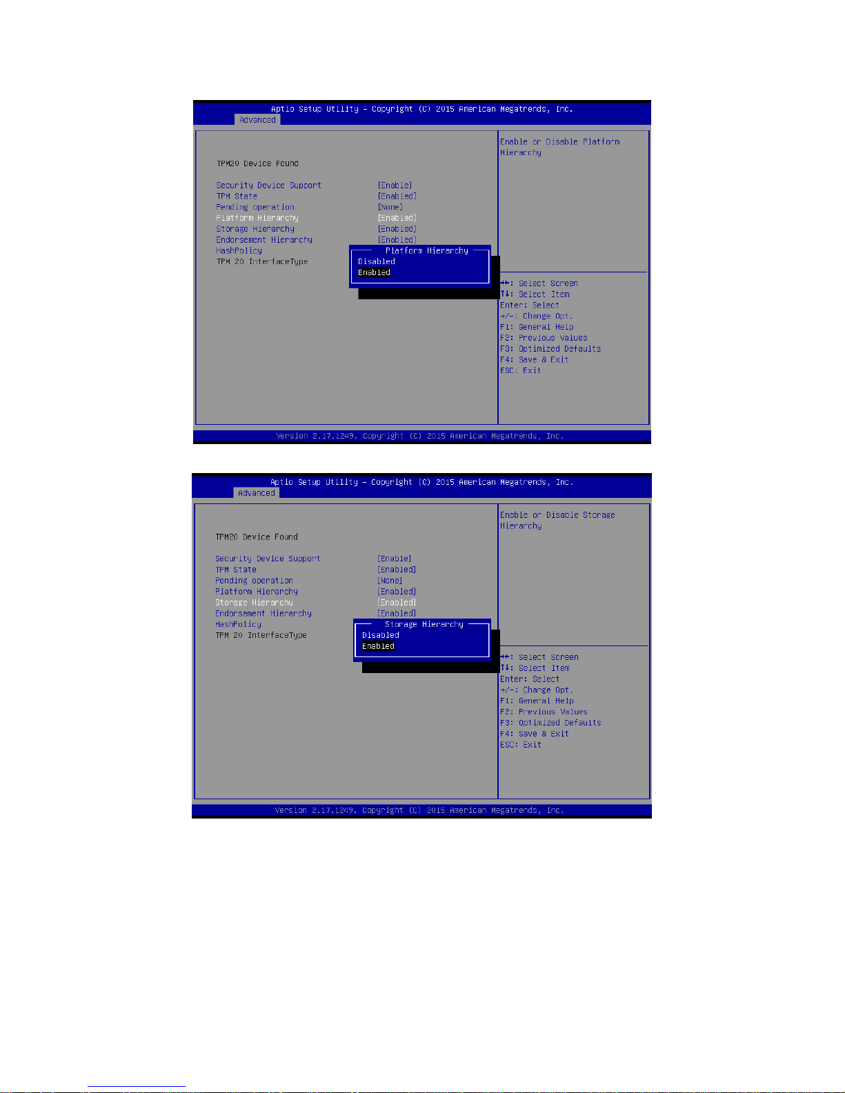
Platform Hierarchy
Disabled,
Enabled[Default]
Enable or Disable Platform Hierarchy.
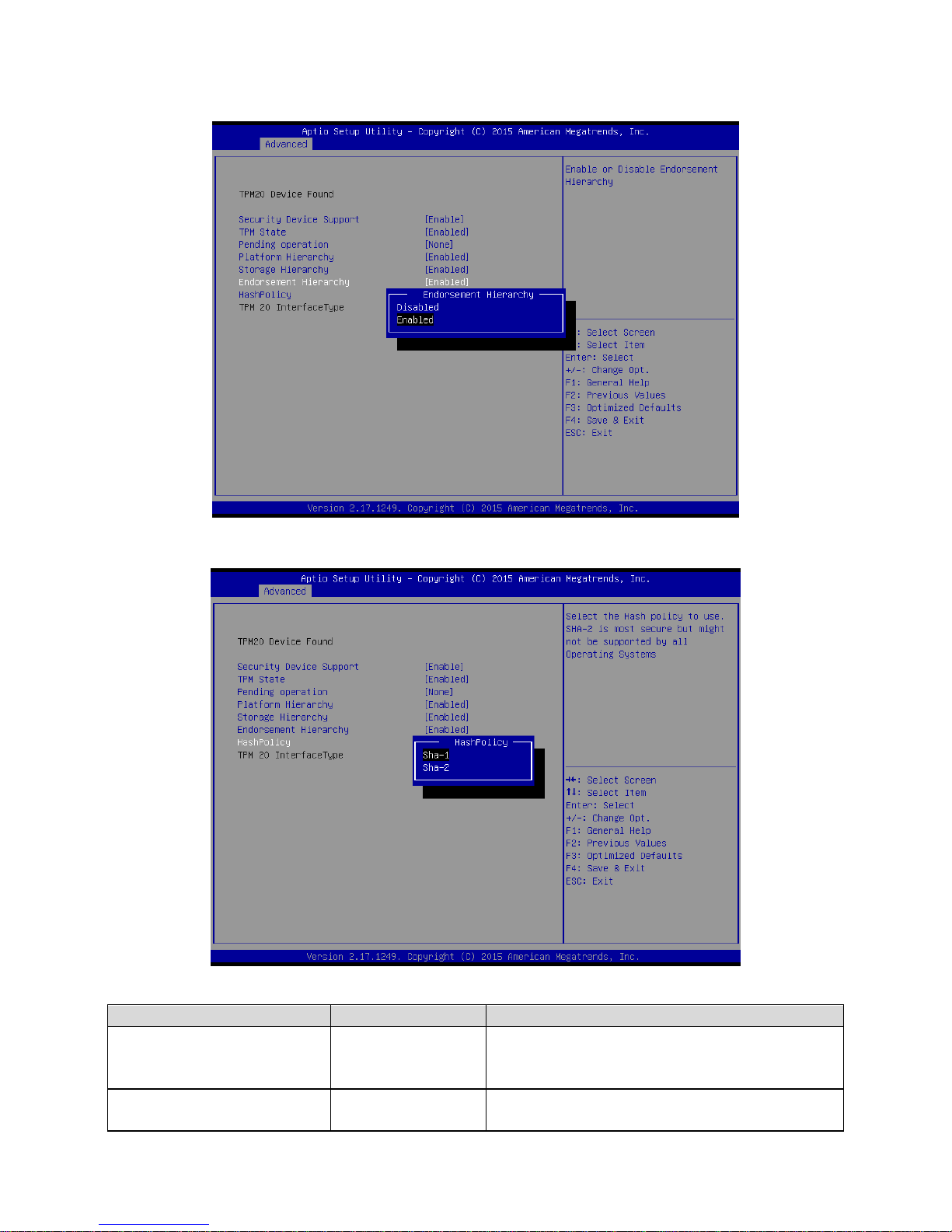
Endorsement Hierarchy
Disabled,
Enabled[Default]
Enable or Disable Endorsement Hierarchy.
HashPolicy
Sha-1[Default]
Sha-2
Select the Hash policy to use. SHA-2 is most secure
but might not be supported by all Operating Systems.
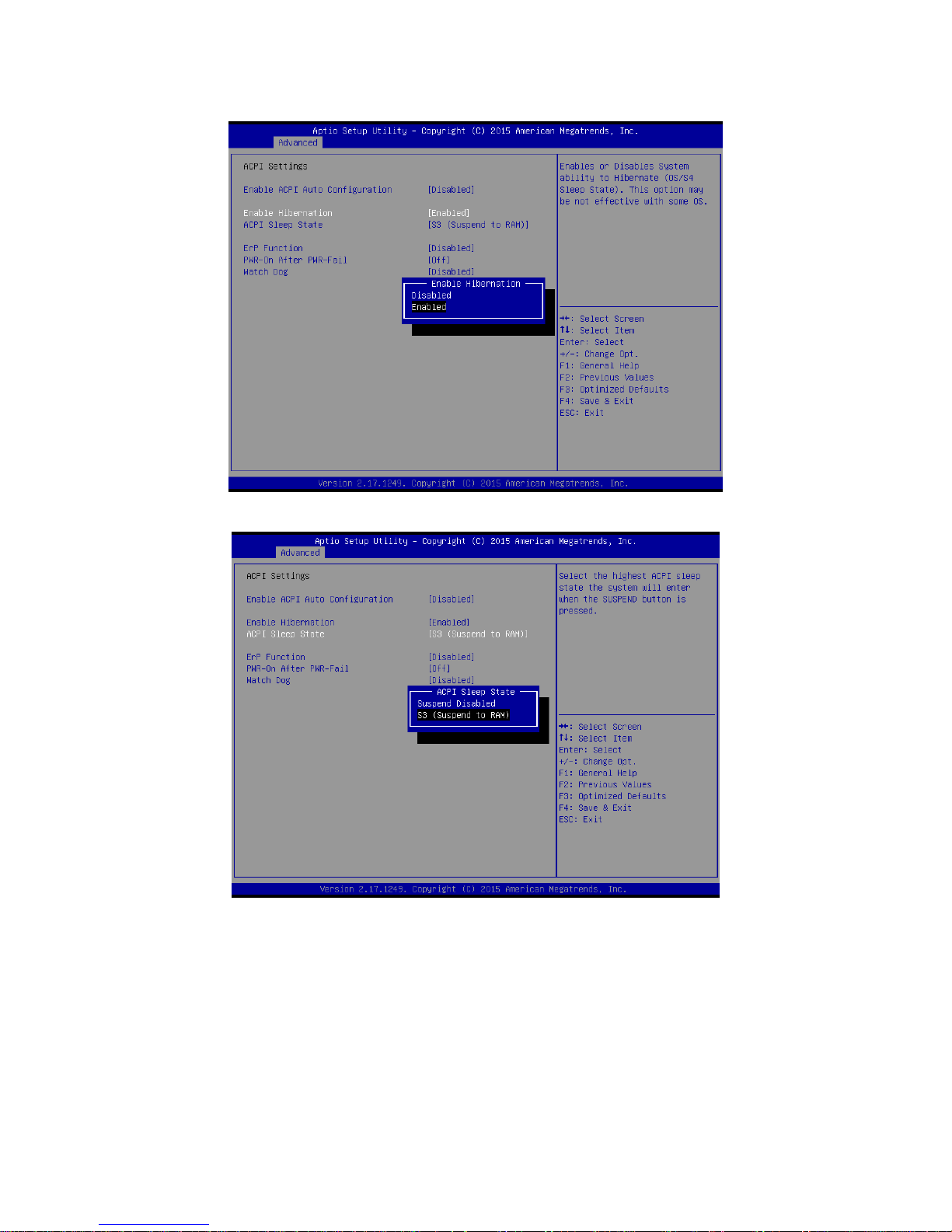
3.6.2.3 APCI Settings
Page 46
EMX-BSWP User’s Manual
46 EMX-BSWP User’s Manual
Page 47
User’s Manual
EMX-BSWP User’s Manual
47
Page 48
EMX-BSWP User’s Manual
48 EMX-BSWP User’s Manual
Item
Options
Description
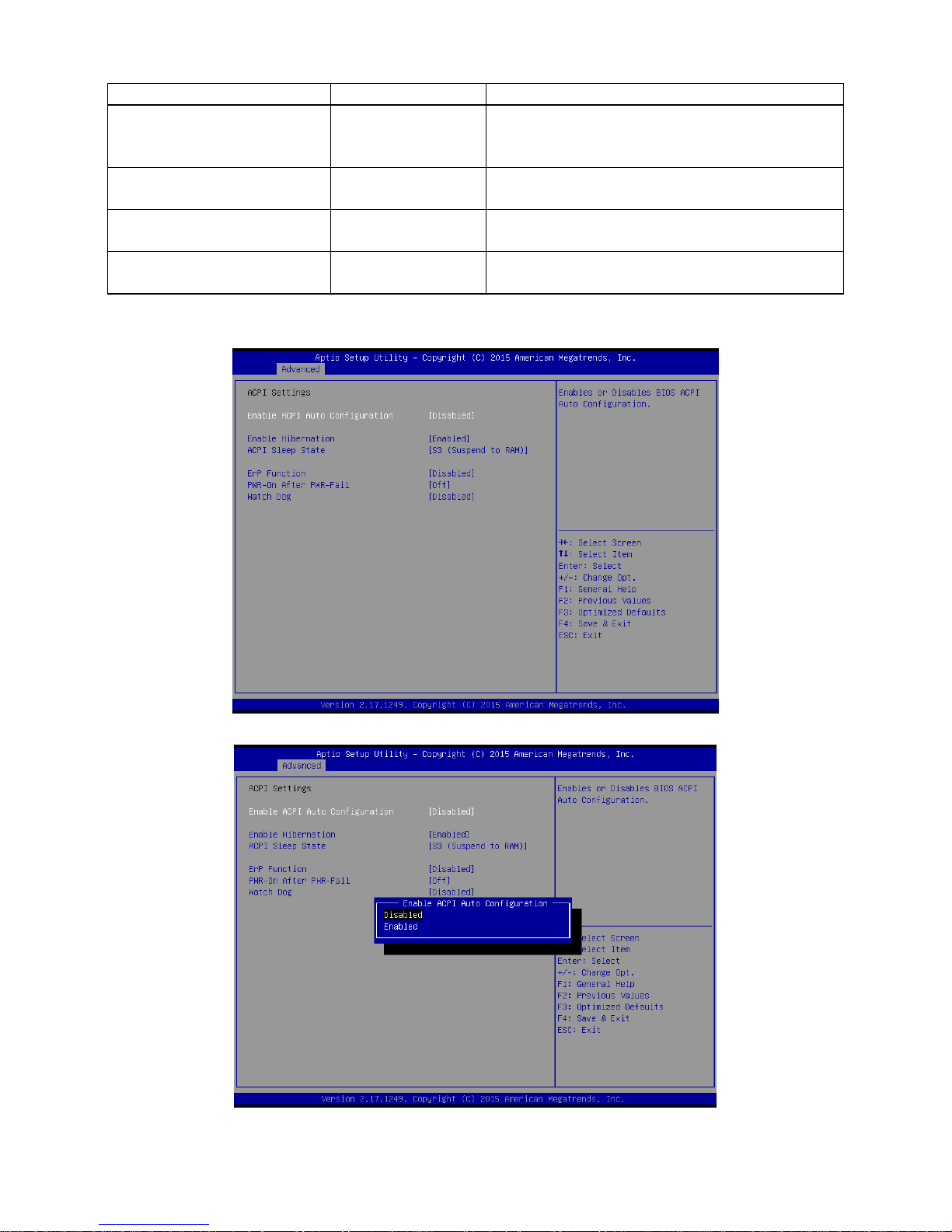
Enable ACPI Auto
Configuration
Disabled[Default],
Enabled
Enables or Disables BIOS ACPI Auto
Configuration.
Enable Hibernation
Disabled
Enabled[Default],
Enables or Disables System ability to
Hibernate (OS/S4 Sleep State). This
option may be not effective with some
OS.
ACPI Sleep State
Suspend Disabled,
S3 (Suspend to RAM)[Default]
Select the highest ACPI sleep state the
system will enter when the SUSPEDN
button is pressed.
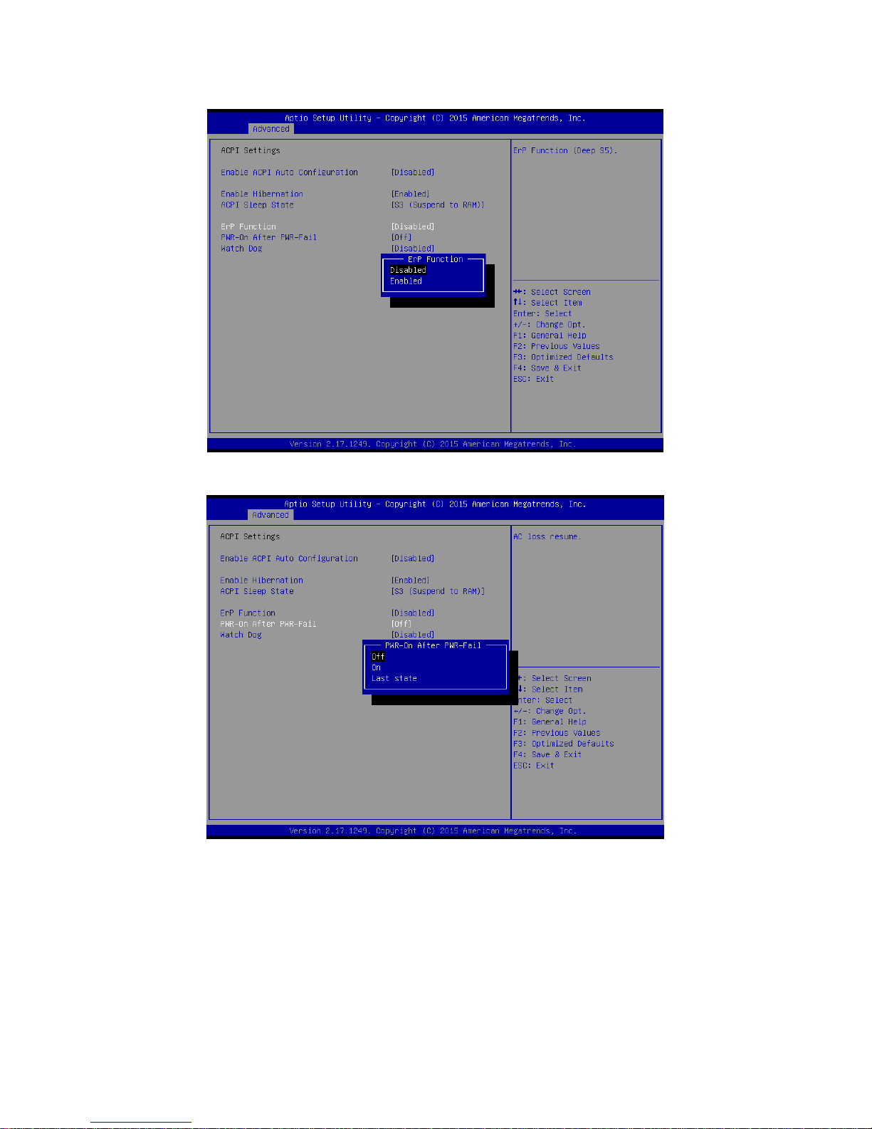
ErP Function
Disabled[Default],
Enabled
ErP Function (Deep S5).
PWR-On After PWR-Fail
Off[Default]
On
Last state
AC loss resume.
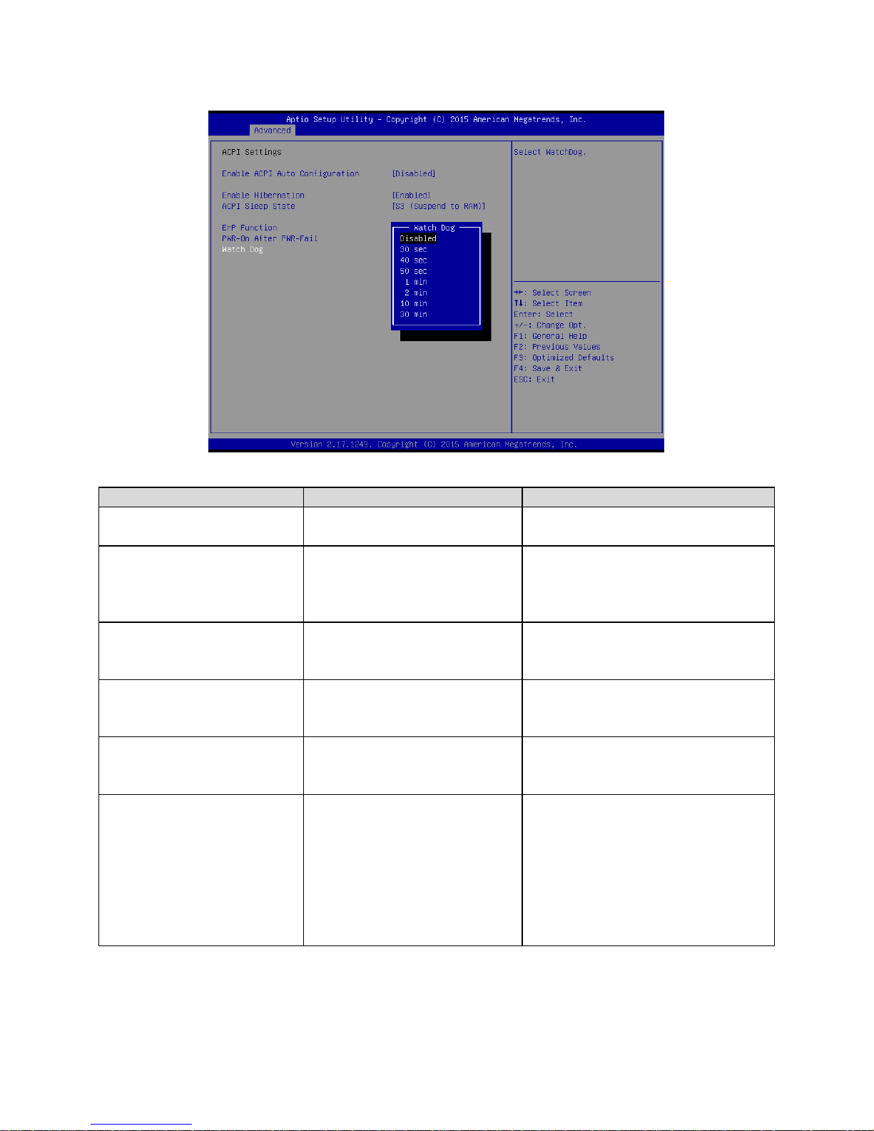
Watch Dog
Disabled[Default],
30 sec
40 sec
50 sec
1 min
2 min
10 min
30 min
Select WatchDog.
Page 49
User’s Manual
EMX-BSWP User’s Manual
49
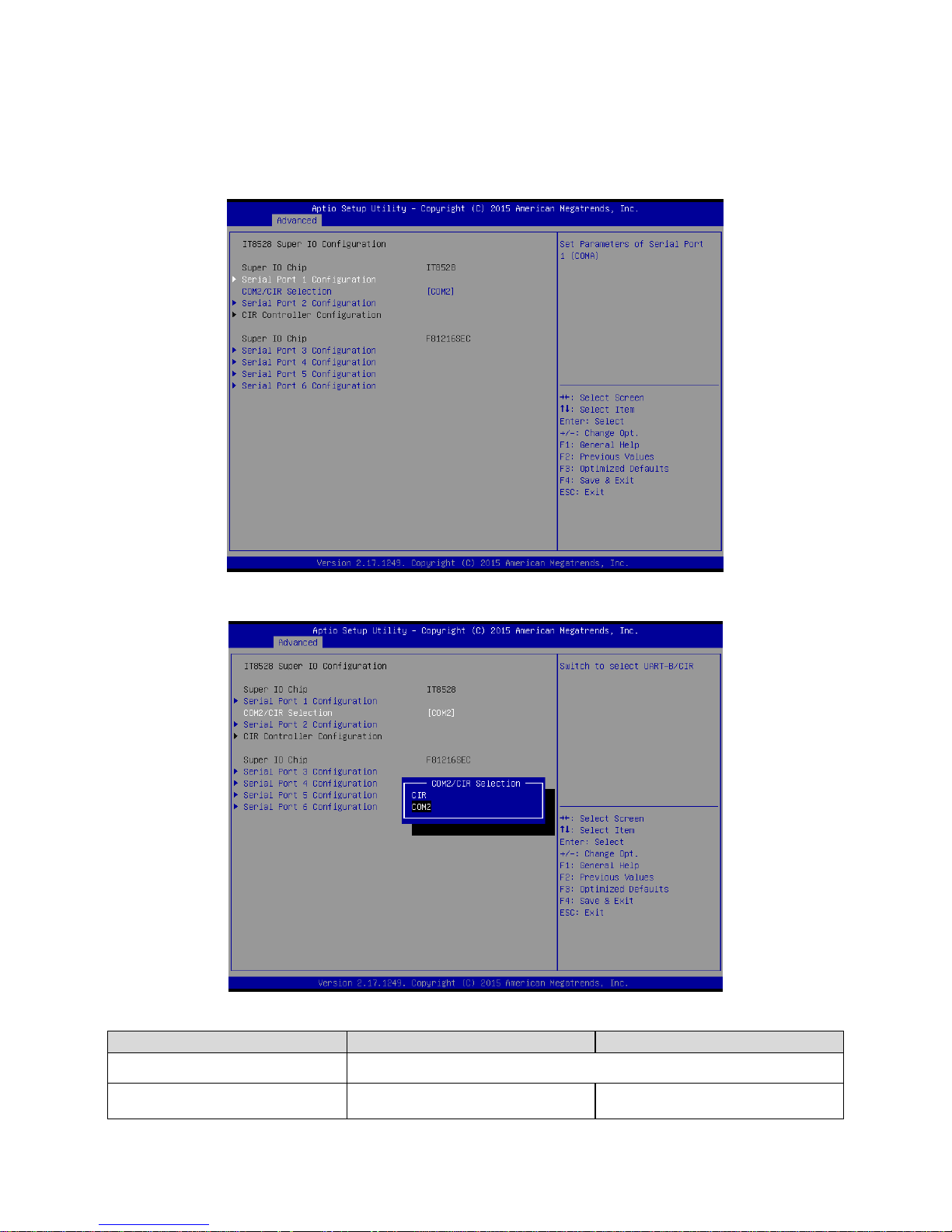
3.6.2.4 IT8528 Super IO Configuration
You can use this item to set up or change the IT8528 Super IO configuration for serial ports.
Please refer to 3.6.2.4.1~ 3.6.2.4.6 for more information.
Item
Options
Description
Serial Port 1 Configuration
Set Parameters of Serial Port 1 (COMA).
COM2/CIR Selection
CIR
COM2[Default],
Switch to select UART-B/CIR.
Page 50
EMX-BSWP User’s Manual
50 EMX-BSWP User’s Manual
Serial Port 2 Configuration
Set Parameters of Serial Port 2 (COMB).
Serial Port 3 Configuration
Set Parameters of Serial Port 3 (COMC).
Serial Port 4 Configuration
Set Parameters of Serial Port 4 (COMD).
Serial Port 5 Configuration
Set Parameters of Serial Port 5 (COME).
Serial Port 6 Configuration
Set Parameters of Serial Port 6 (COMF).
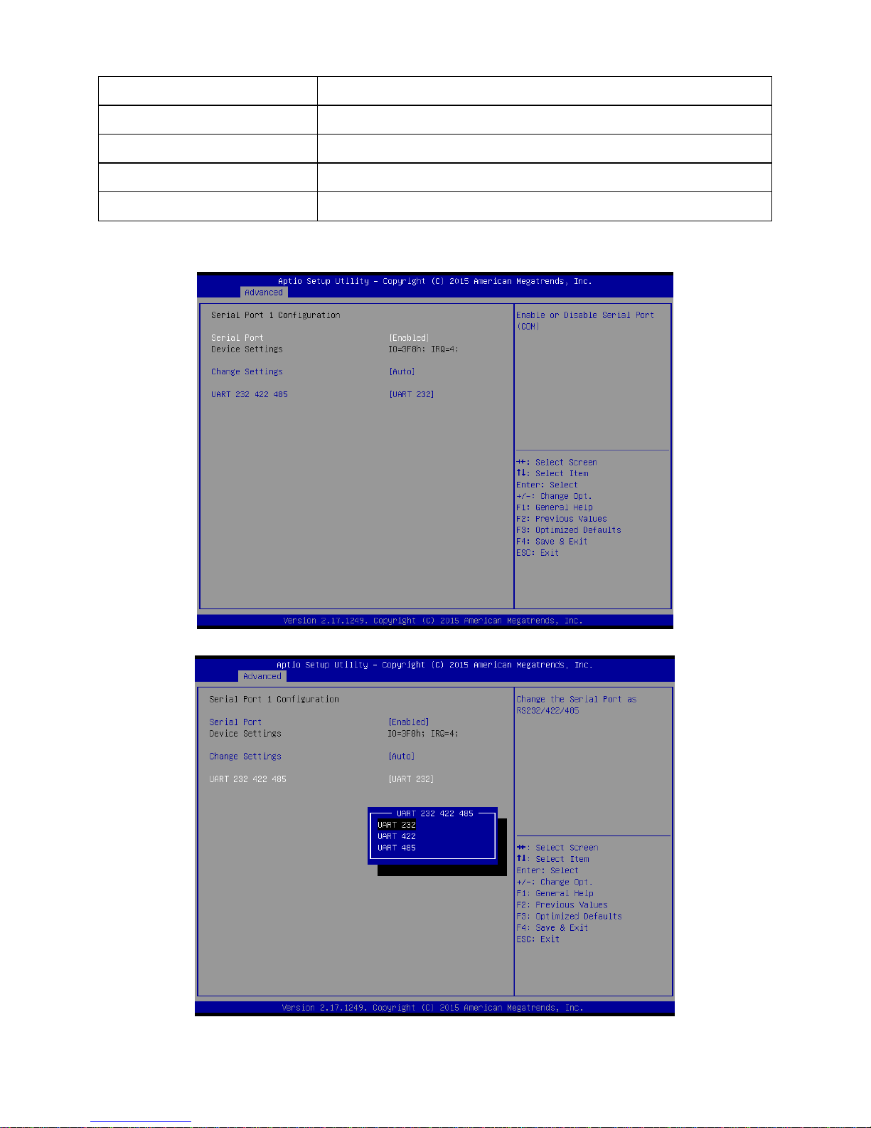
3.6.2.4.1 Serial Port 1 Configuration
Page 51
User’s Manual
EMX-BSWP User’s Manual
51
Item
Option
Description
Serial Port
Enabled[Default],
Disabled
Enable or Disable Serial Port
(COM).
Change Settings
Auto[Default]
IO=3F8h; IRQ=4;
IO=3F8h; IRQ=3,4,5,6,7,9,10,11,12;
IO=2F8h; IRQ=3,4,5,6,7,9,10,11,12;
IO=3E8h; IRQ=3,4,5,6,7,9,10,11,12;
IO=2E8h; IRQ=3,4,5,6,7,9,10,11,12;
Select an optimal setting for
Super IO Device.
UART 232 422 485
UART 232[Default],
UART 422,
UART 485
Change the Serial Port as
RS232/ 422/ 485
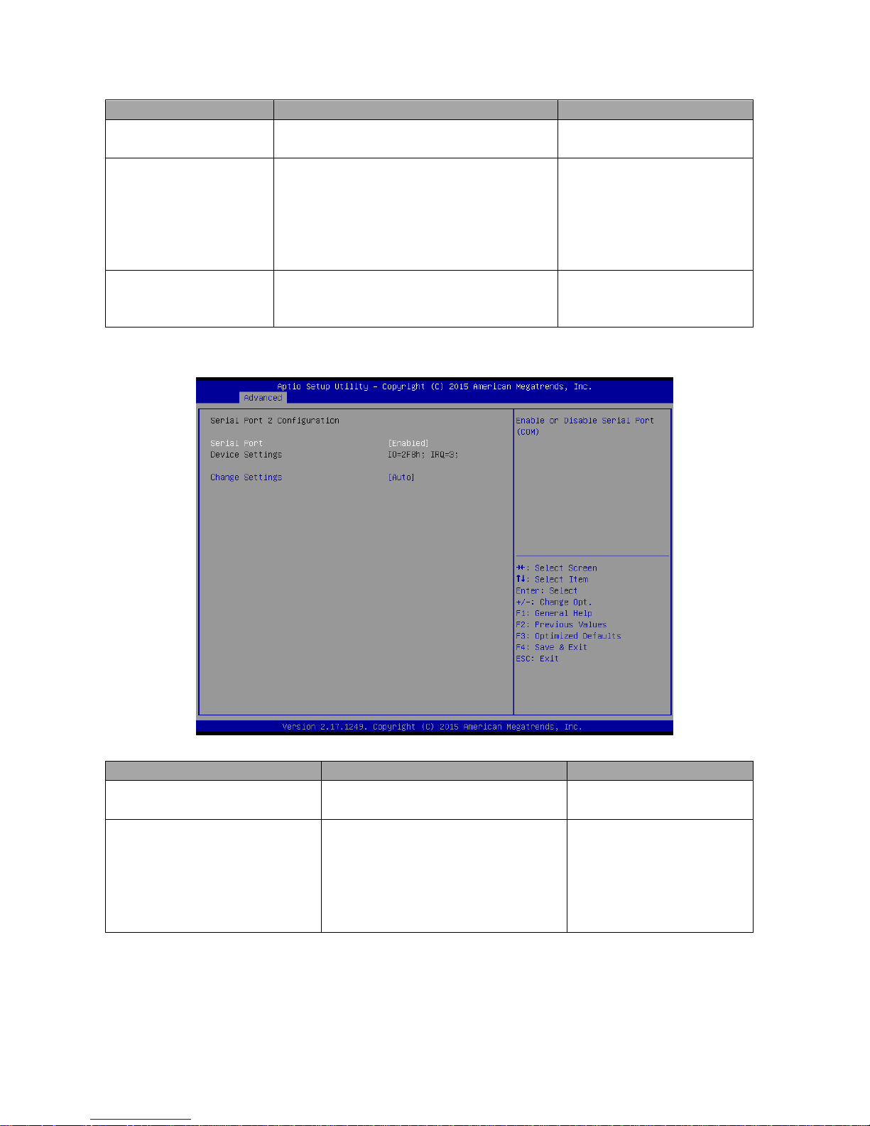
3.6.2.4.2 Serial Port 2 Configuration
Item
Option
Description
Serial Port
Enabled[Default],
Disabled
Enable or Disable Serial Port
(COM).
Change Settings
Auto[Default]
IO=2F8h; IRQ=3;
IO=3F8h; IRQ=3,4,5,6,7,9,10,11,12;
IO=2F8h; IRQ=3,4,5,6,7,9,10,11,12;
IO=3E8h; IRQ=3,4,5,6,7,9,10,11,12;
IO=2E8h; IRQ=3,4,5,6,7,9,10,11,12;
Select an optimal setting for
super IO Device.
Page 52
EMX-BSWP User’s Manual
52 EMX-BSWP User’s Manual
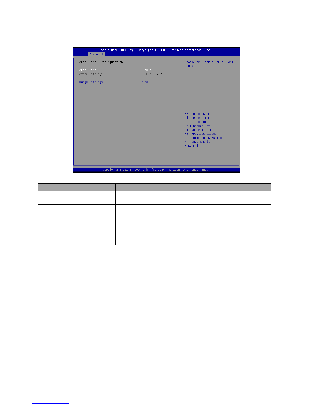
3.6.2.4.3 Serial Port 3 Configuration
Item
Option
Description
Serial Port
Enabled[Default],
Disabled
Enable or Disable Serial Port
(COM).
Change Settings
Auto[Default]
IO=3E8h; IRQ=5;
IO=3E8h; IRQ=3,4,5,6,7,10,11,12;
IO=2E8h; IRQ=3,4,5,6,7,10,11,12;
IO=200h; IRQ=3,4,5,6,7,10,11,12;
IO=208h; IRQ=3,4,5,6,7,10,11,12;
Select an optimal setting for
super IO Device.
Page 53
User’s Manual
EMX-BSWP User’s Manual
53
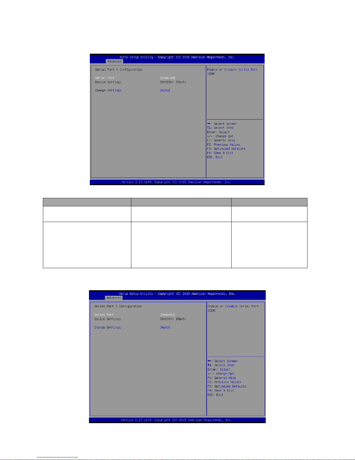
3.6.2.4.4 Serial Port 4 Configuration
Item
Option
Description
Serial Port
Enabled[Default],
Disabled
Enable or Disable Serial Port
(COM).
Change Settings
Auto[Default]
IO=2E8h; IRQ=5;
IO=3E8h; IRQ=3,4,5,6,7,10,11,12;
IO=2E8h; IRQ=3,4,5,6,7,10,11,12;
IO=200h; IRQ=3,4,5,6,7,10,11,12;
IO=208h; IRQ=3,4,5,6,7,10,11,12;
Select an optimal setting for
super IO Device.
3.6.2.4.5 Serial Port 5 Configuration
Page 54
EMX-BSWP User’s Manual
54 EMX-BSWP User’s Manual
Item
Option
Description
Serial Port
Enabled[Default],
Disabled
Enable or Disable Serial Port
(COM).
Change Settings
Auto[Default]
IO=200h; IRQ=5;
IO=3E8h; IRQ=3,4,5,6,7,10,11,12;
IO=2E8h; IRQ=3,4,5,6,7,10,11,12;
IO=200h; IRQ=3,4,5,6,7,10,11,12;
IO=208h; IRQ=3,4,5,6,7,10,11,12;
Select an optimal setting for
super IO Device.
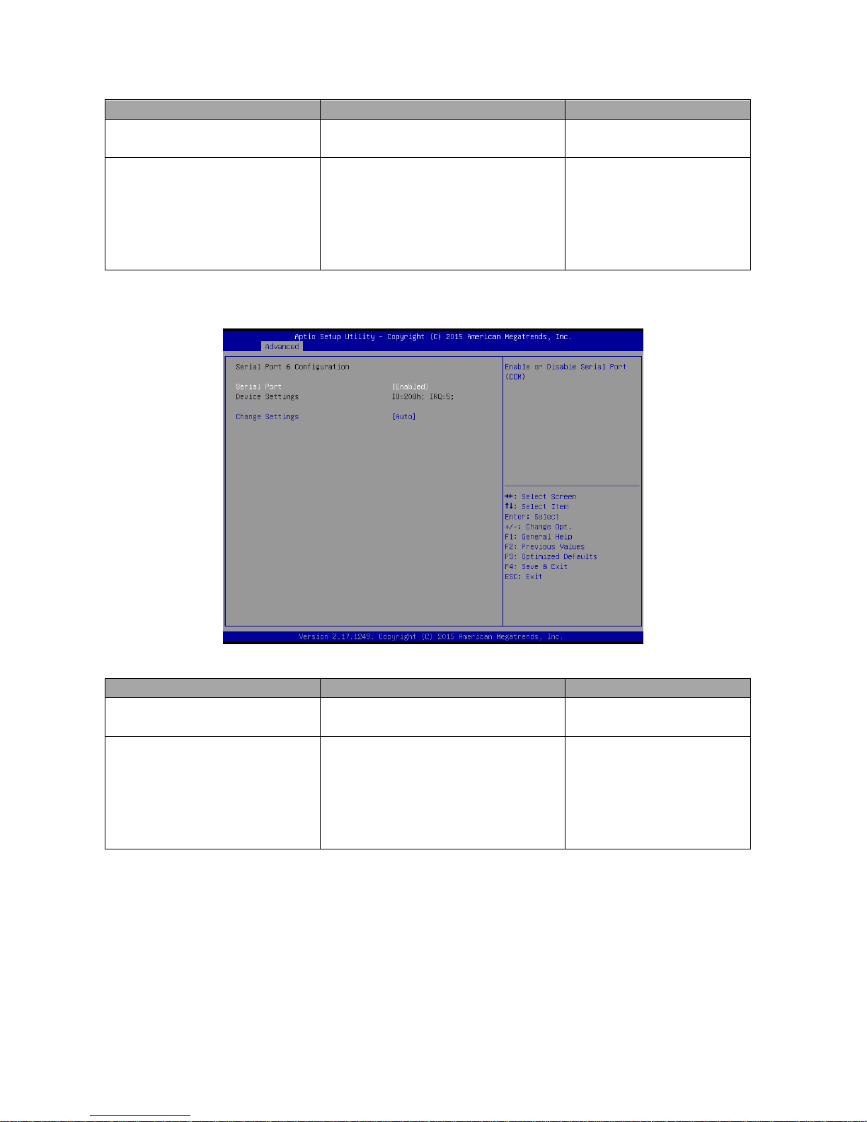
3.6.2.4.6 Serial Port 6 Configuration
Item
Option
Description
Serial Port
Enabled[Default],
Disabled
Enable or Disable Serial Port
(COM).
Change Settings
Auto[Default]
IO=208h; IRQ=5;
IO=3E8h; IRQ=3,4,5,6,7,10,11,12;
IO=2E8h; IRQ=3,4,5,6,7,10,11,12;
IO=200h; IRQ=3,4,5,6,7,10,11,12;
IO=208h; IRQ=3,4,5,6,7,10,11,12;
Select an optimal setting for
super IO Device.
Page 55
User’s Manual
EMX-BSWP User’s Manual
55
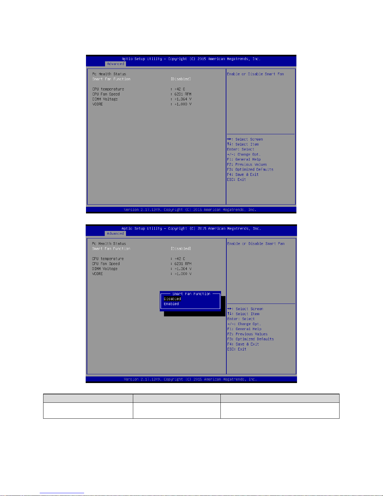
3.6.2.5 H/W Monitor
Item
Options
Description
Smart Fan Function
Enabled,
Disabled[Default]
Enable or Disable Smart Fan.
Page 56
EMX-BSWP User’s Manual
56 EMX-BSWP User’s Manual
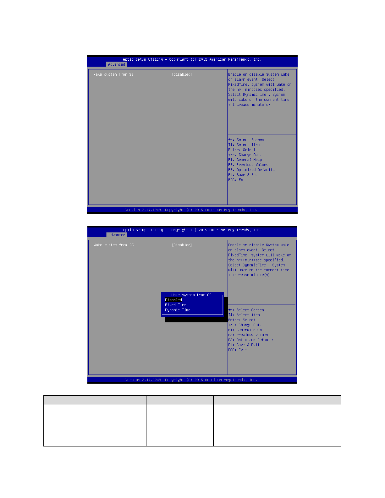
3.6.2.6 S5 RTC Wake Settings
Item
Options
Description
Wake system from S5
Disabled[Default],
Fixed Time
Dynamic Time
Enable or disable System wake on alarm
event. Select Fixed Time, system will wake on
the hr::min::sec specified. Select Dynamic
Time, System will wake on the current time +
Increase minute(s).
Page 57
User’s Manual
EMX-BSWP User’s Manual
57
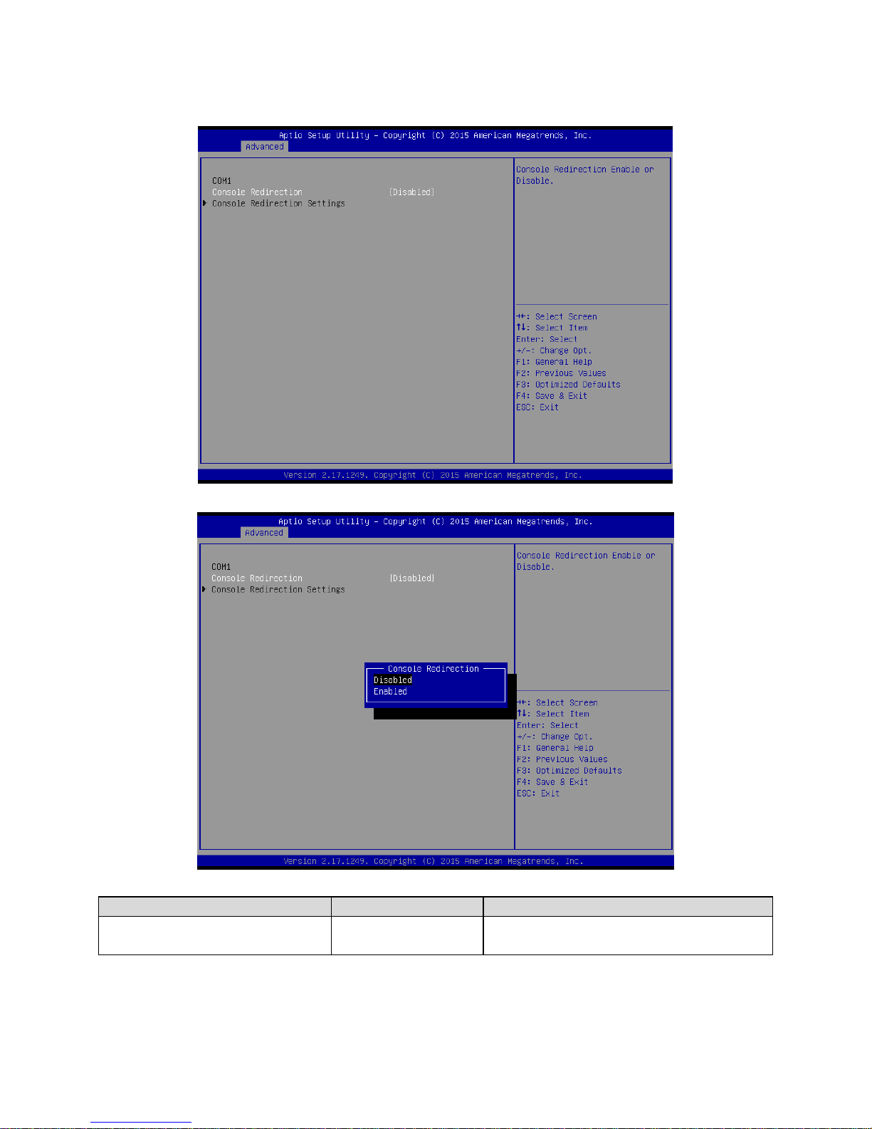
3.6.2.7 Serial Port Console Redirection
Item
Options
Description
Console Redirection
Disabled[Default],
Enabled
Console Redirection Enable or Disable.
Page 58
EMX-BSWP User’s Manual
58 EMX-BSWP User’s Manual
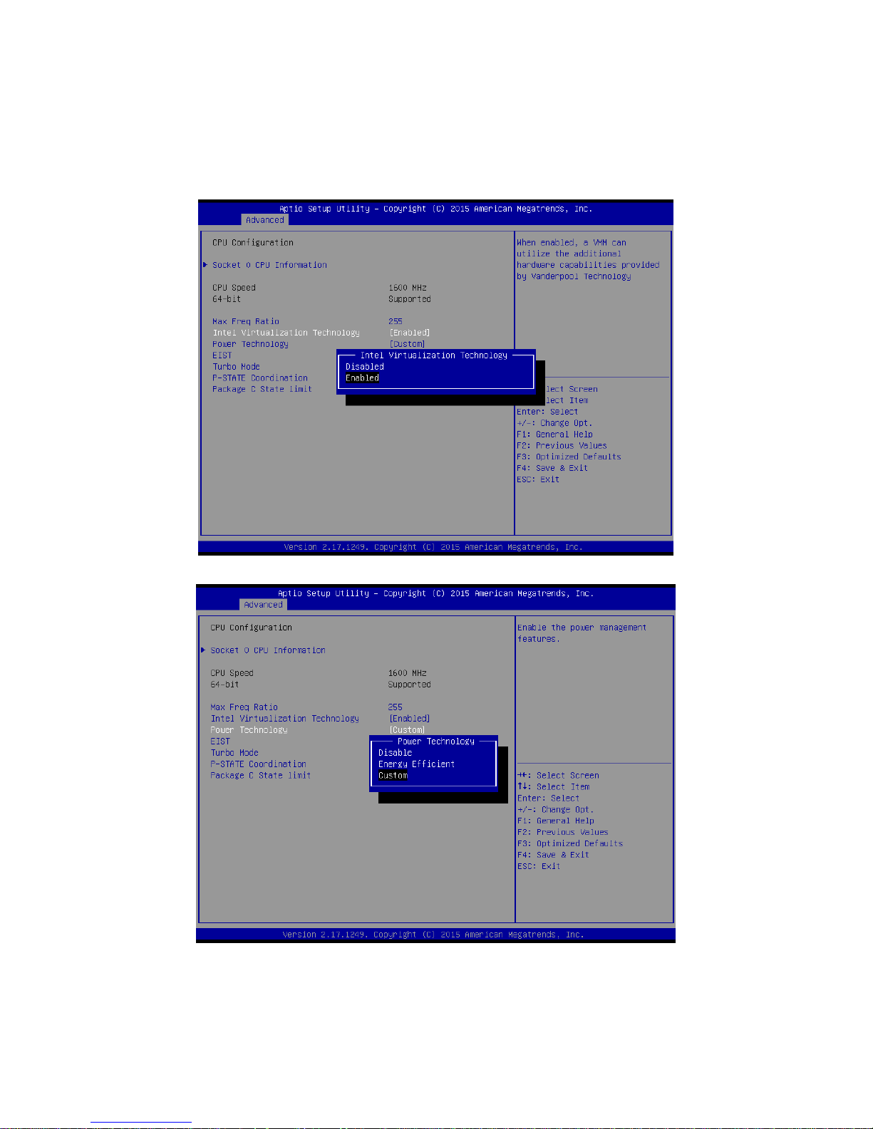
3.6.2.8 CPU Configuration
Use the CPU configuration menu to view detailed CPU specification and configure the
CPU.
Page 59

User’s Manual
EMX-BSWP User’s Manual
59
Page 60

EMX-BSWP User’s Manual
60 EMX-BSWP User’s Manual
Item
Options
Description
Max Freq Ratio
0-255
Max Freq Ratio.
Intel Virtualization Technology
Disabled,
Enabled[Default]
When enabled, a VMM can utilize the
additional hardware capabilities provided by
Virtualization Technology.
Power Technology
Disabled,
Energy Efficient
Custom[Default]
Enable the power management features.
Page 61
User’s Manual
EMX-BSWP User’s Manual
61
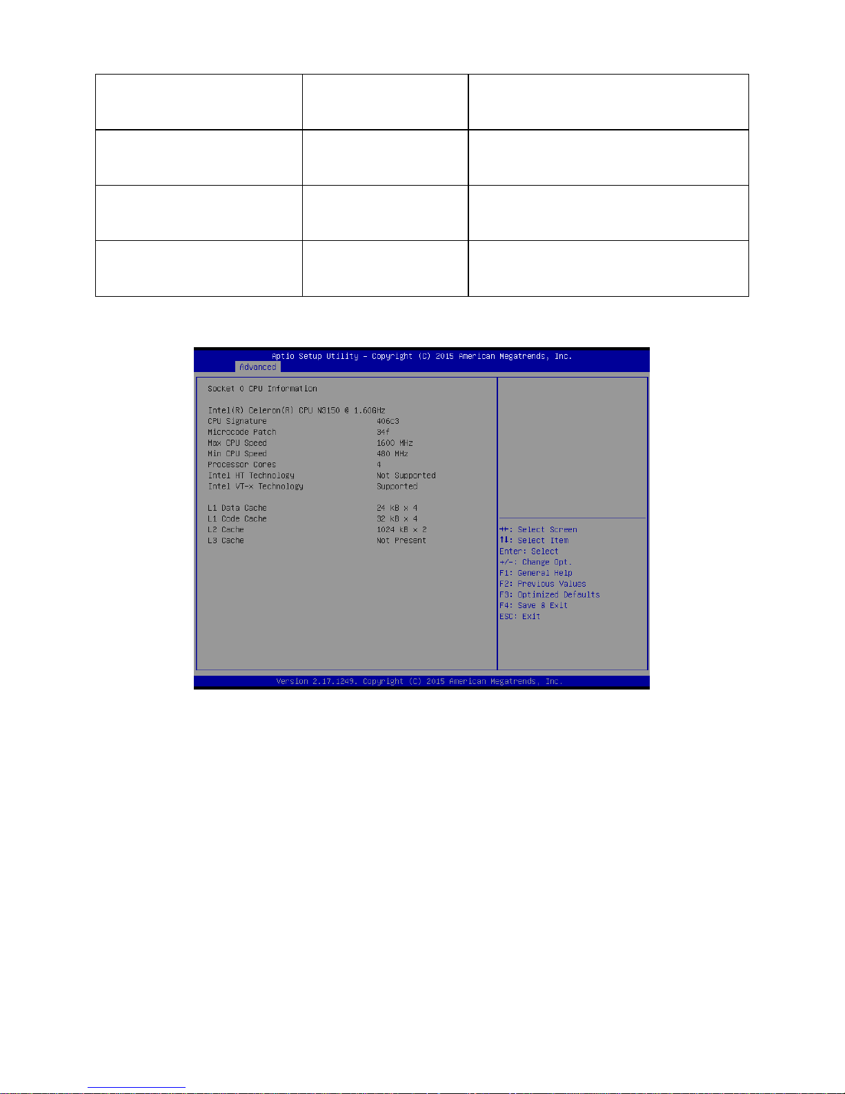
EIST
Disabled,
Enabled[Default]
Enable/Disable Intel SpeedStep.
Turbo Mode
Disabled,
Enabled[Default]
Turbo Mode.
P-STATE Coordination
HW_ALL[Default]
SW_ALL
SW_ANY
Change P-STATE Coordination type.
Package C State limit
C1[Default]/3/6/7
Package C State limit.
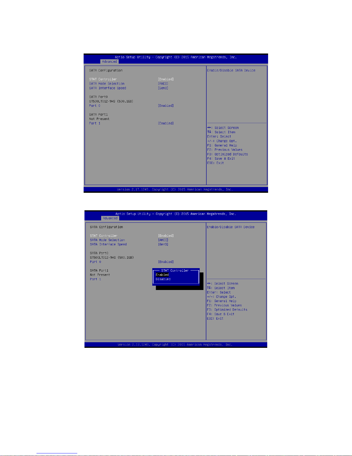
3.6.2.8.1 Socket 0 CPU Information
Page 62
EMX-BSWP User’s Manual
62 EMX-BSWP User’s Manual
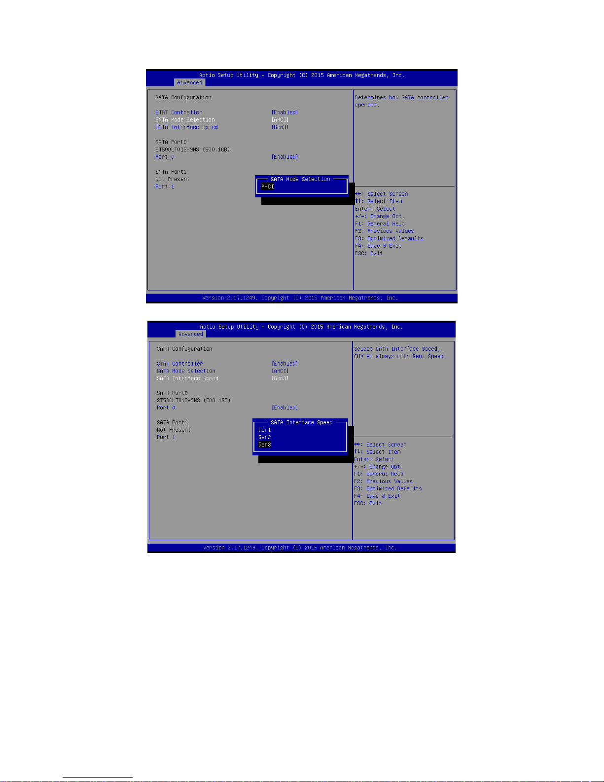
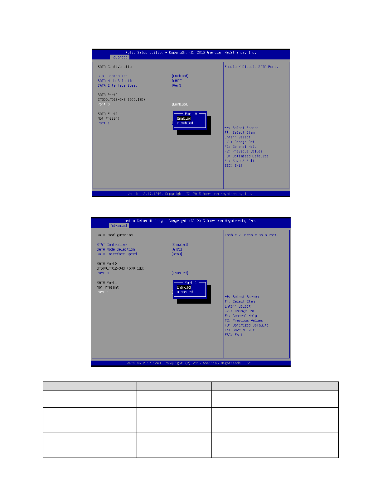
3.6.2.9 SATA Configuration
Page 63
User’s Manual
EMX-BSWP User’s Manual
63
Page 64
EMX-BSWP User’s Manual
64 EMX-BSWP User’s Manual
Item
Options
Description
SATA Controller
Disabled,
Enabled[Default]
Enable/Disable SATA Device.
SATA Mode Selection
AHCI[Default]
Determines how SATA controller operate.
SATA Interface Speed
Gen1
Gen2
Gen3[Default]
Select SATA Interface Speed, CHV A1 always
with Gen 1 Speed.
Page 65
User’s Manual
EMX-BSWP User’s Manual
65
Port0/1
Disabled,
Enabled[Default]
Enable/Disable SATA Port.
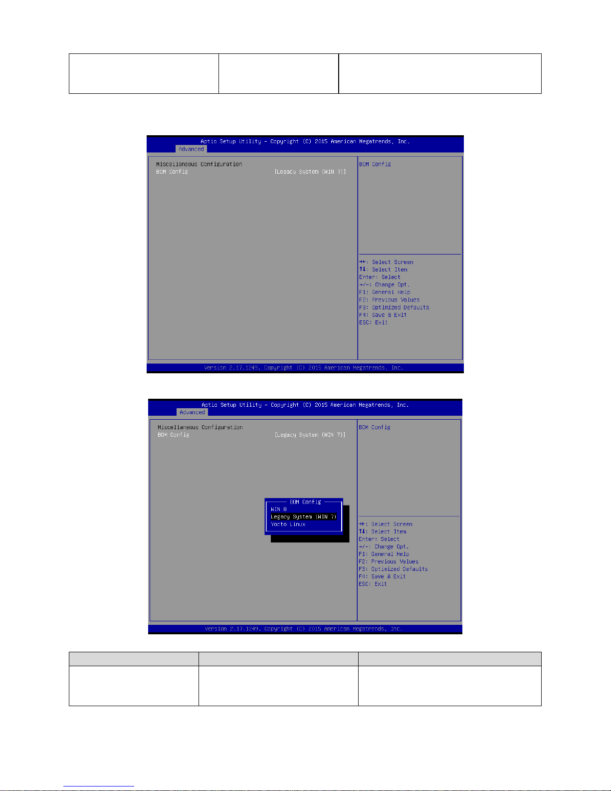
3.6.2.10 Miscellaneous Configuration
Item
Options
Description
BOM Config
Win8
Legacy System (WIN 7)[Default]
Yocto Linux
Select OS type to install.
Page 66
EMX-BSWP User’s Manual
66 EMX-BSWP User’s Manual
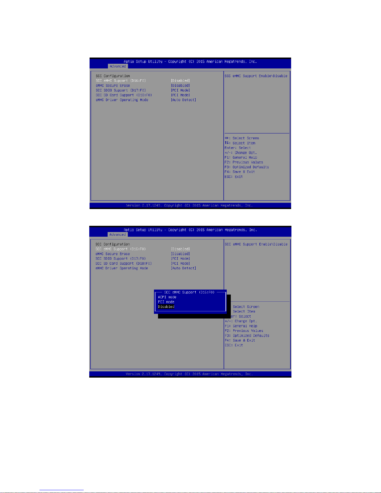
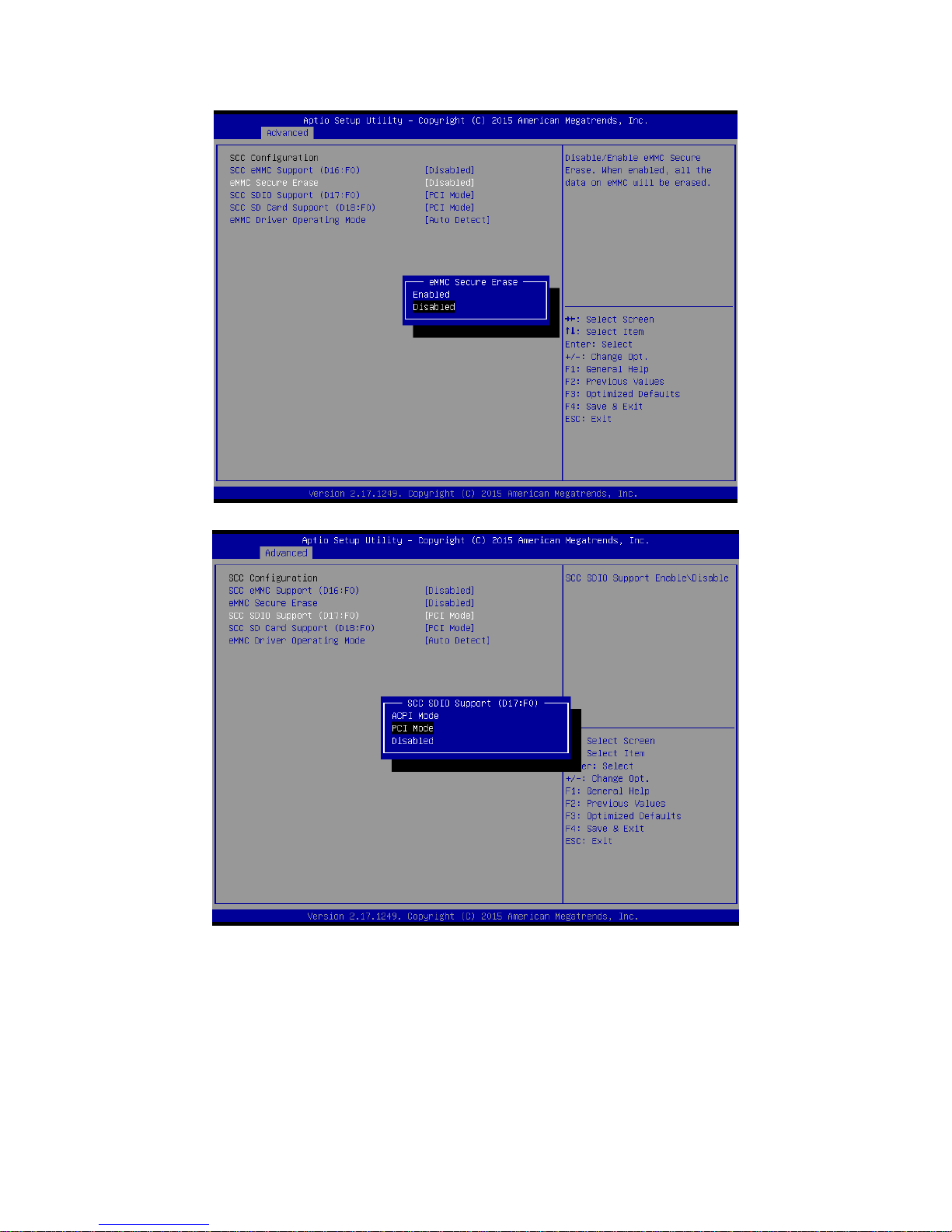
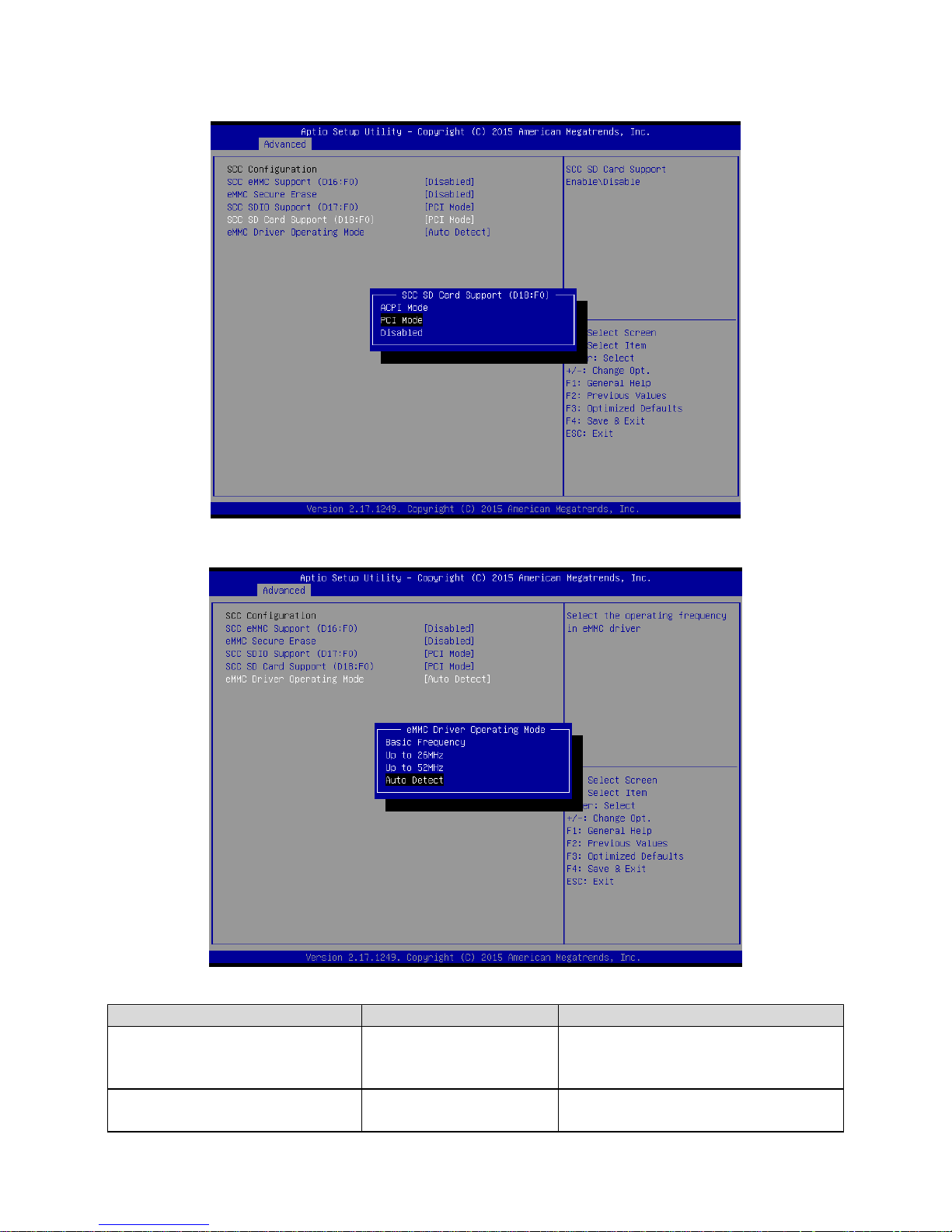
3.6.2.11 LPSS & SCC Configuration
Page 67
User’s Manual
EMX-BSWP User’s Manual
67
Page 68
EMX-BSWP User’s Manual
68 EMX-BSWP User’s Manual
Item
Options
Description
SCC eMMC Support (D16:F0)
ACPI Mode
PCI Mode
Disabled[Default]
SCC eMMC power management function
support selection.
eMMC Secure Erase
Enabled
Disabled[Default]
Disable/Enable eMMC Secure Erase.
When enabled, all the data on eMMC will
Page 69
User’s Manual
EMX-BSWP User’s Manual
69
be erased.
SCC SDIO Support (D17:F0)
ACPI Mode
PCI Mode[Default]
Disabled
SCC SDIO Support Enable/Disable.
SCC SD Card Support (D18:F0)
ACPI Mode
PCI Mode[Default]
Disabled
SCC SD Card Support Enable/Disable.
eMMC Driver Operating Mode
Basic Frequency
Up to 26MHz
Up to 52MHz
Auto Detect[Default]
Select the operating frequency in eMMC
driver.
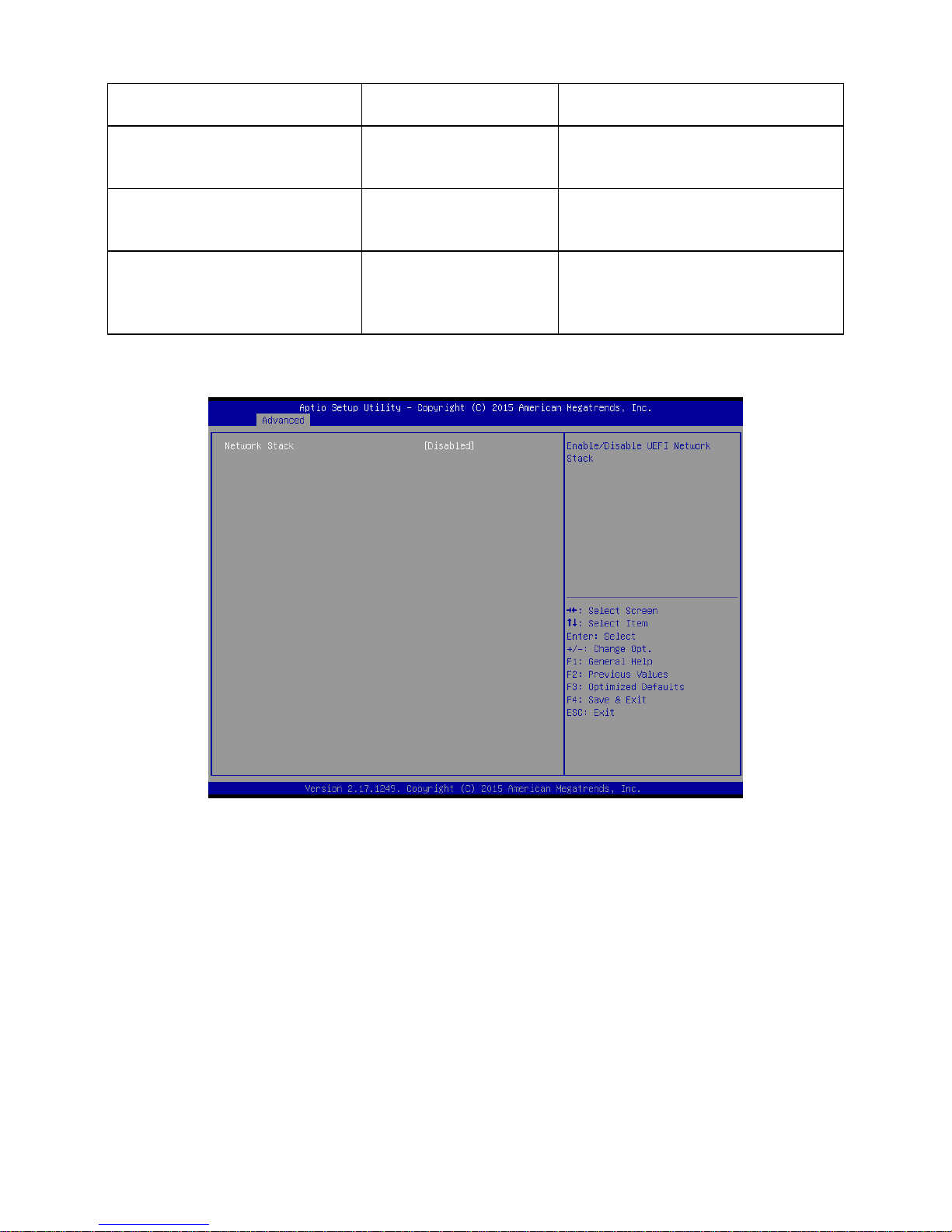
3.6.2.12 Network Stack Configuration
Page 70

EMX-BSWP User’s Manual
70 EMX-BSWP User’s Manual
Item
Options
Description
Network Stack
Enabled
Disabled[Default]
Enable/Disable UEFI Network Stack.
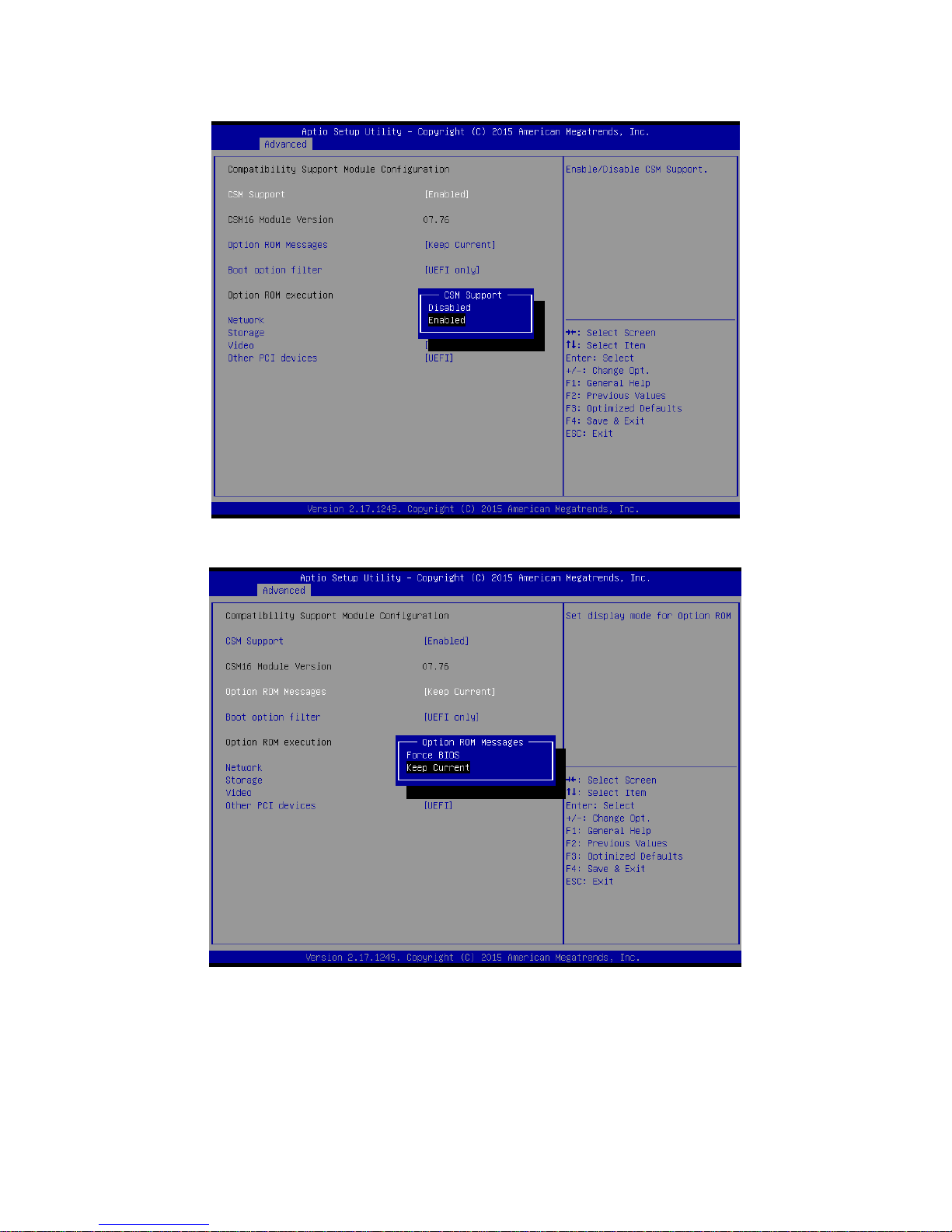
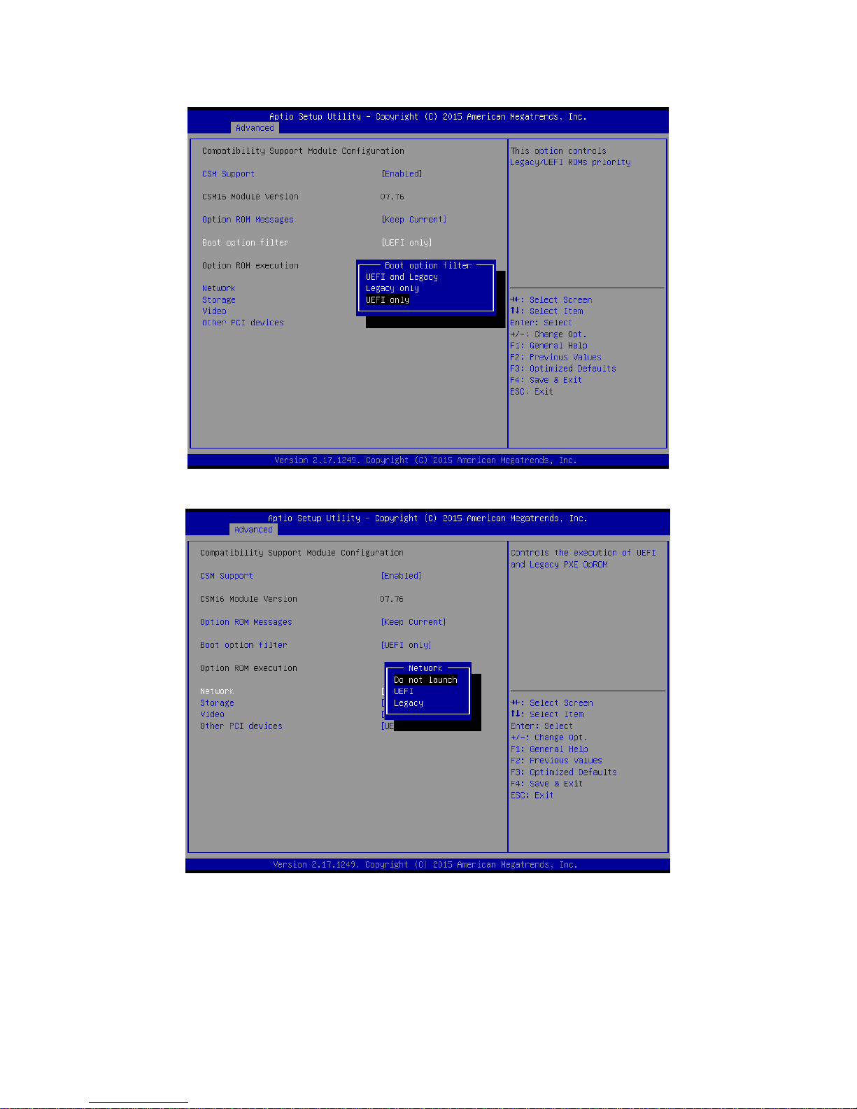
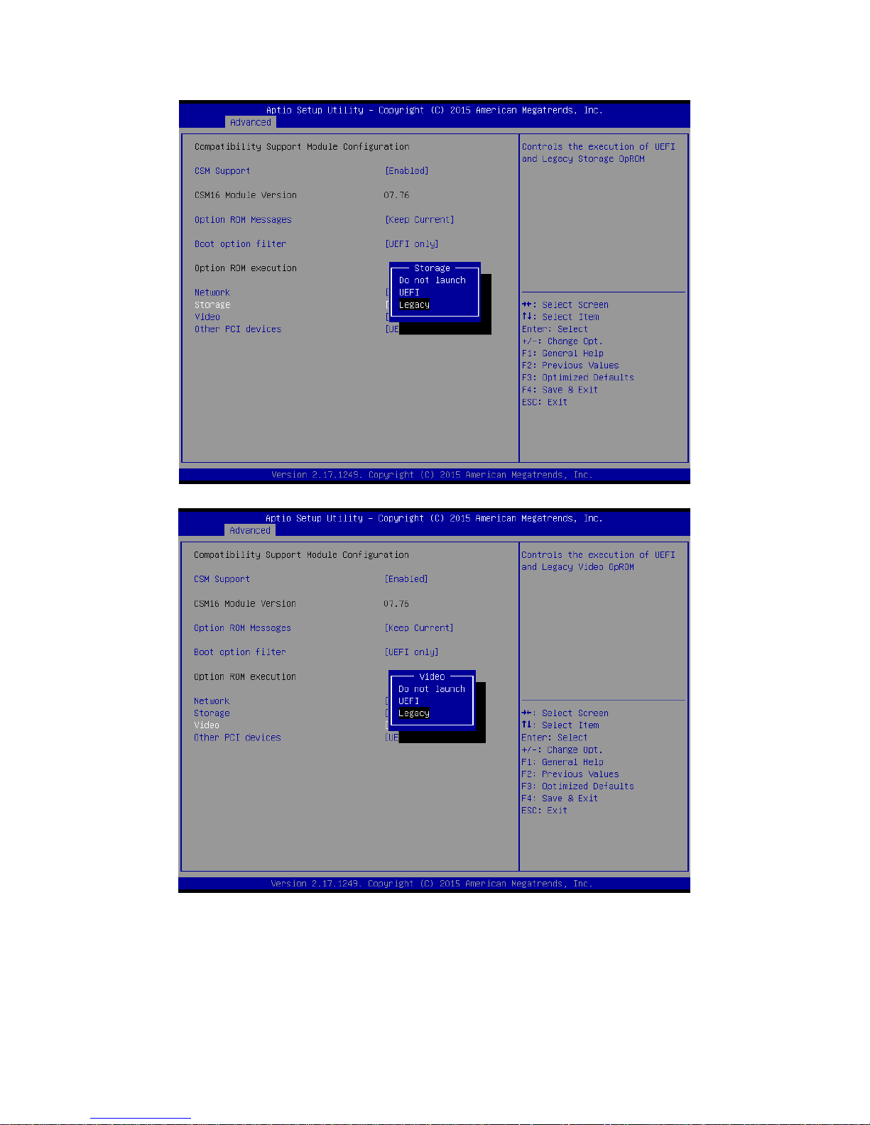
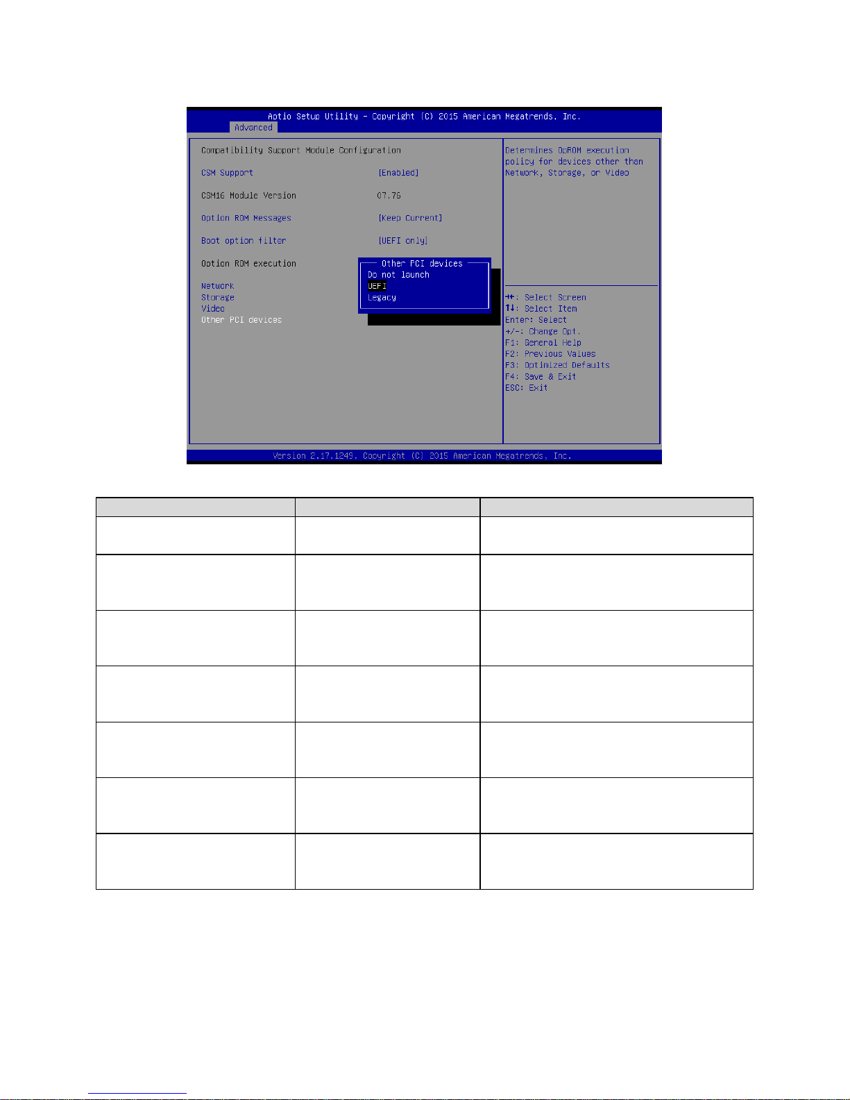
3.6.2.13 CSM Configuration
Page 71
User’s Manual
EMX-BSWP User’s Manual
71
Page 72
EMX-BSWP User’s Manual
72 EMX-BSWP User’s Manual
Page 73
User’s Manual
EMX-BSWP User’s Manual
73
Page 74
EMX-BSWP User’s Manual
74 EMX-BSWP User’s Manual
Item
Options
Description
CSM Support
Enabled[Default]
Disabled,
Enable/Disable CSM Support.
Option ROM Messages
Force BIOS
Keep Current[Default]
Set display mode for Option ROM.
Boot option filter
UEFI and Legacy
Legacy only
UEFI only[Default]
This option controls Legacy/UEFI ROMs
priority.
Network
Do not launch[Default]
UEFI
Legacy
Controls the execution of UEFI and Legacy
PXE OpROM.
Storage
Do not launch
UEFI
Legacy[Default]
Controls the execution of UEFI and Legacy
Storage OpROM.
Video
Do not launch
UEFI
Legacy[Default]
Controls the execution of UEFI and Legacy
Video OpROM.
Other PCI devices
Do not launch
UEFI[Default]
Legacy
Determines OpROM execution policy for
devices other than Network, Storage, or
Video.
Page 75
User’s Manual
EMX-BSWP User’s Manual
75
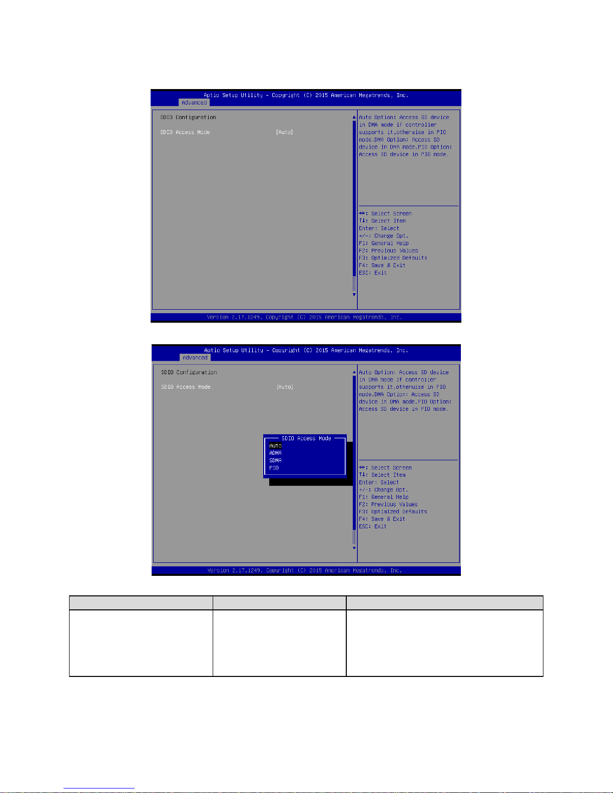
3.6.2.14 SDIO Configuration
Item
Options
Description
SDIO Access Mode
Auto[Default]
ADMA
SDMA
PIO
Auto Option: Access SD device in DMA
mode if controller supports it , otherwise in
PIO mode. DMA Option: Access SD device
in DMA mode. PIO Option: Access SD
device in PIO mode.
Page 76
EMX-BSWP User’s Manual
76 EMX-BSWP User’s Manual
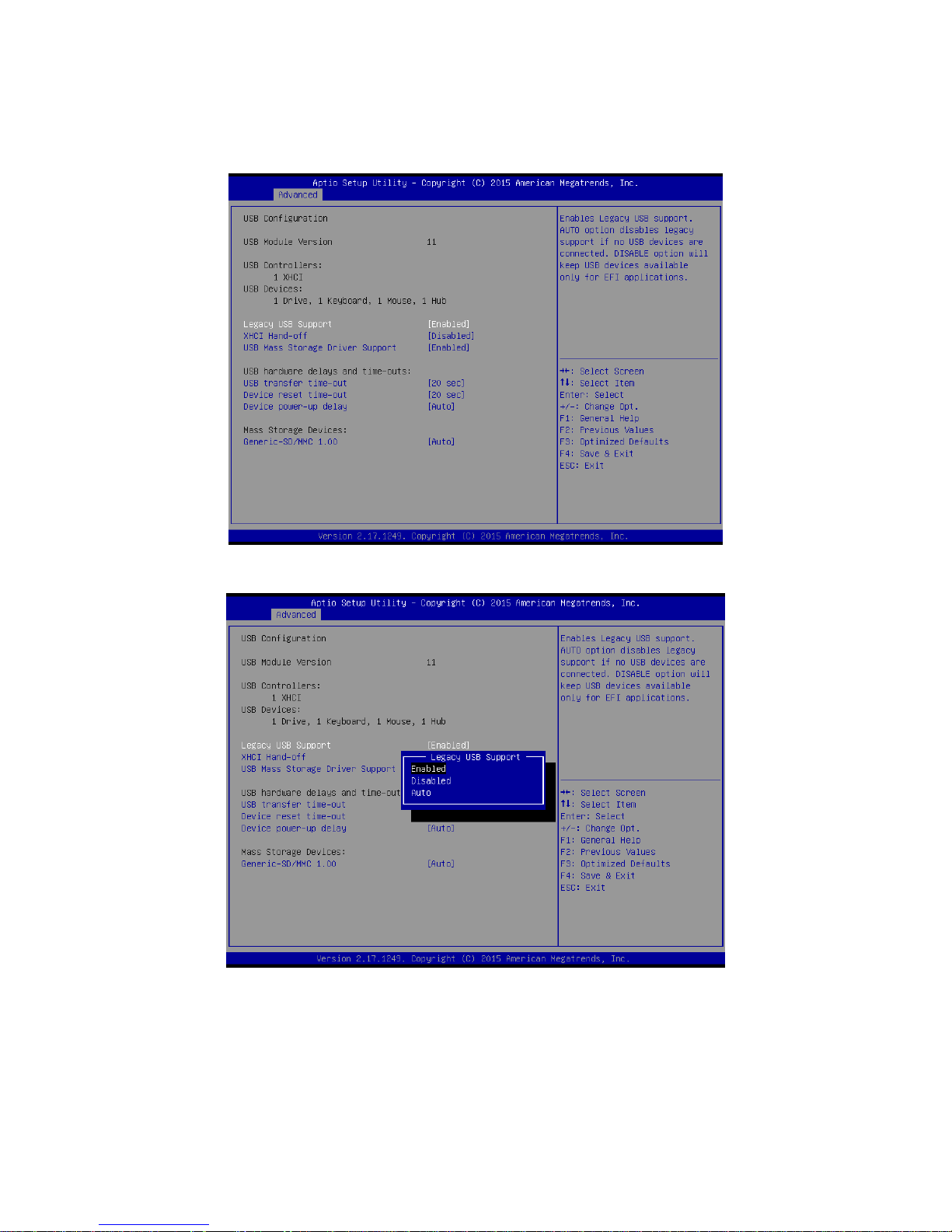
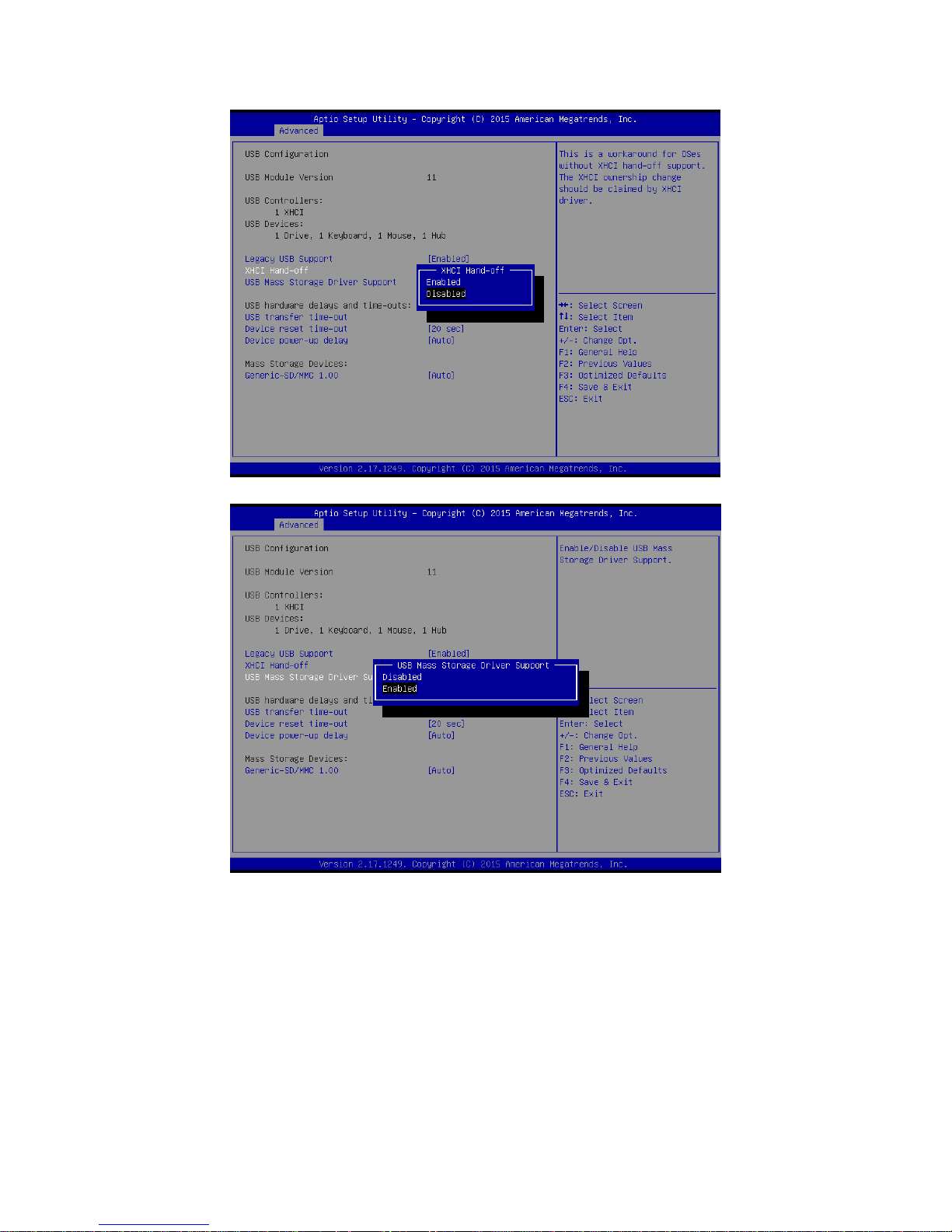
3.6.2.15 USB Configuration
The USB Configuration menu helps read USB information and configures USB settings.
Page 77
User’s Manual
EMX-BSWP User’s Manual
77
Page 78
EMX-BSWP User’s Manual
78 EMX-BSWP User’s Manual
Page 79
User’s Manual
EMX-BSWP User’s Manual
79
Item
Options
Description
Legacy USB Support
Enabled[Default]
Disabled
Auto
Enables Legacy USB support. AUTO option
disables legacy support if no USB devices are
connected. DISABLE option will keep USB
devices available only for EFI applications.
XHCI Hand-off
Enabled
Disabled[Default]
This is a workaround for OSew without XHCI
hand-off support. The XHCI ownership change
should be claimed by XHCI driver.
USB Mass Storage Driver Support
Enabled[Default]
Enable/Disable USB Mass Storage Driver
Page 80
EMX-BSWP User’s Manual
80 EMX-BSWP User’s Manual
Disabled
Support.
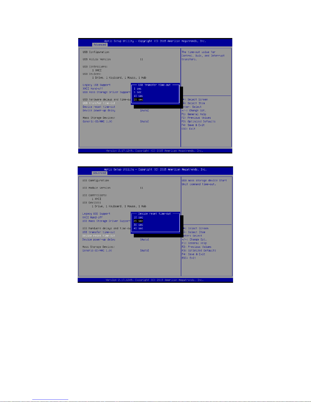
USB transfer time-out
1 sec
5 sec
10 sec
20 sec[Default]
The time-out value for Control, Bulk, and Interrupt
transfers.
Device reset time-out
10 sec
20 sec[Default]
30 sec
40 sec
USB mass storage device Start Unit command
time-out.
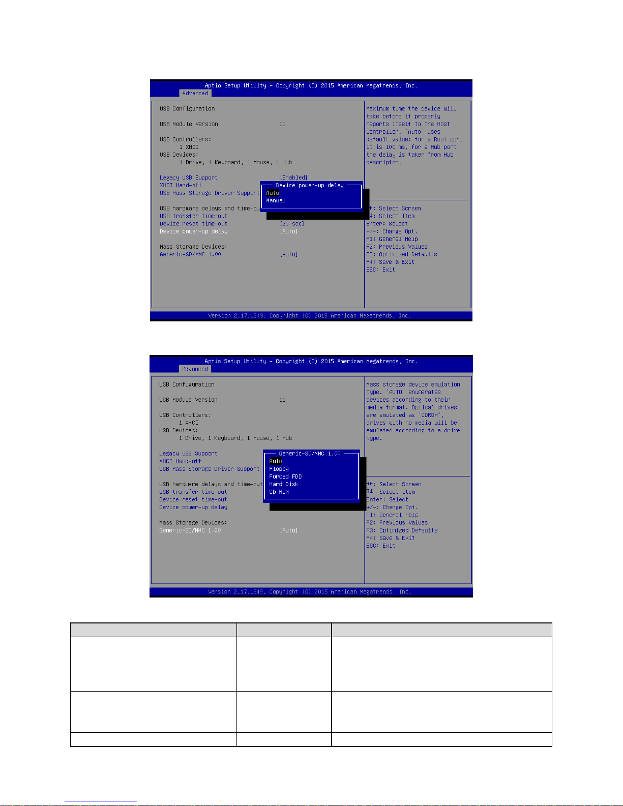
Device power-up delay
Auto[Default]
Manual
Maximum time the device will take before it
properly reports itself to the Host Controller. ‘Auto’
uses default value: for a Root port it is 100ms, for
a Hub port the delay is taken form Hub descriptor.
Generic-SD/MMC 1.00
Auto[Default]
Floppy
Forced FDD
Hard Disk
CD-ROM
Mass storage device emulation type. ‘AUTO’
enumerates devices according to their media
format. Optical drives are emulated as ‘CDROM’,
drives with no media will be emulated according
to a drive type.
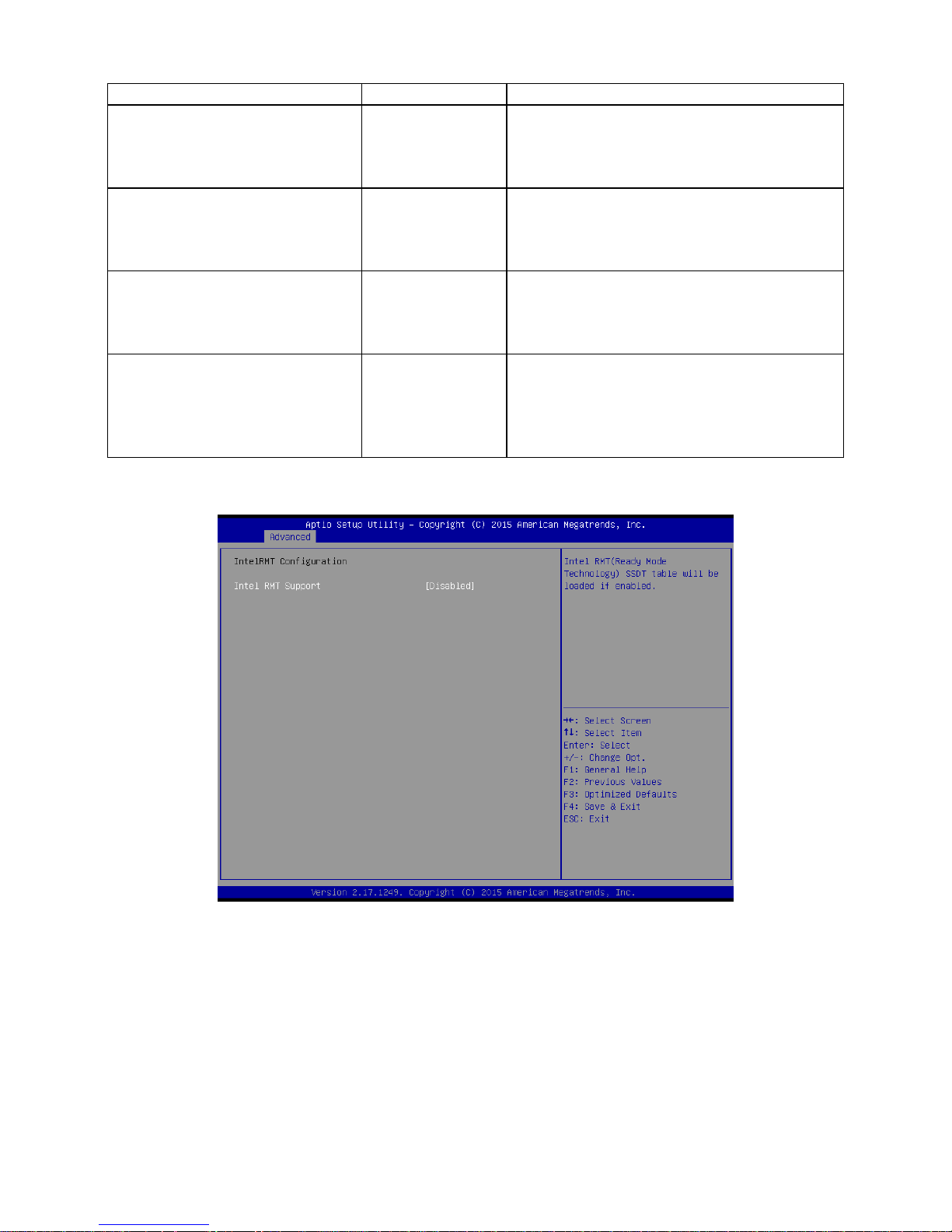
3.6.2.16 IntelRMT Configuration
Page 81
User’s Manual
EMX-BSWP User’s Manual
81
Item
Options
Description
Intel RMT Support
Disabled[Default]
Enabled,
Intel RMT(Ready Mode Technology) SSDT table will
be loaded if enabled.
3.6.3 Chipset
Page 82
EMX-BSWP User’s Manual
82 EMX-BSWP User’s Manual
3.6.3.1 North Bridge
Item
Option
Description
Max TOLUD
2 GB
3 GB[Default]
Maximum Value of TOLUD.
Page 83
User’s Manual
EMX-BSWP User’s Manual
83
3.6.3.1.1 Intel IGD Configuration
Page 84
EMX-BSWP User’s Manual
84 EMX-BSWP User’s Manual
Item
Option
Description
VGA Enabled/Disabled
Setting
Enabled[Default],
Disabled
Enable GOP Driver will unload
VBIOS; Disable it will load VBIOS.
Primary Display
IGD
PCIe
Auto[Default]
Select which of IGD/PCI Graphics
device should be Primary Display.
GFX Boost
Enabled,
Disabled[Default]
Enable/Disable GFX Boost.
Page 85
User’s Manual
EMX-BSWP User’s Manual
85
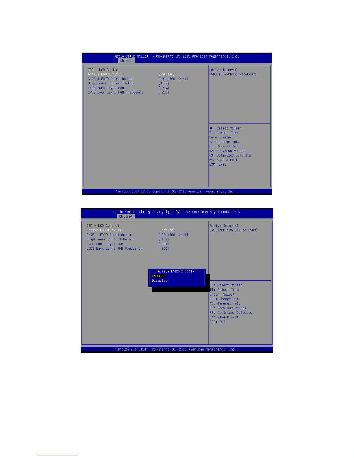
3.6.3.1.2 IGD - LCD Control
Page 86
EMX-BSWP User’s Manual
86 EMX-BSWP User’s Manual
Page 87
User’s Manual
EMX-BSWP User’s Manual
87
Item
Option
Description
Active LVDS (Ch7511)
Enabled[Default]
Disabled
Active Internal LVDS(eDP->Ch7511to –LVDS).
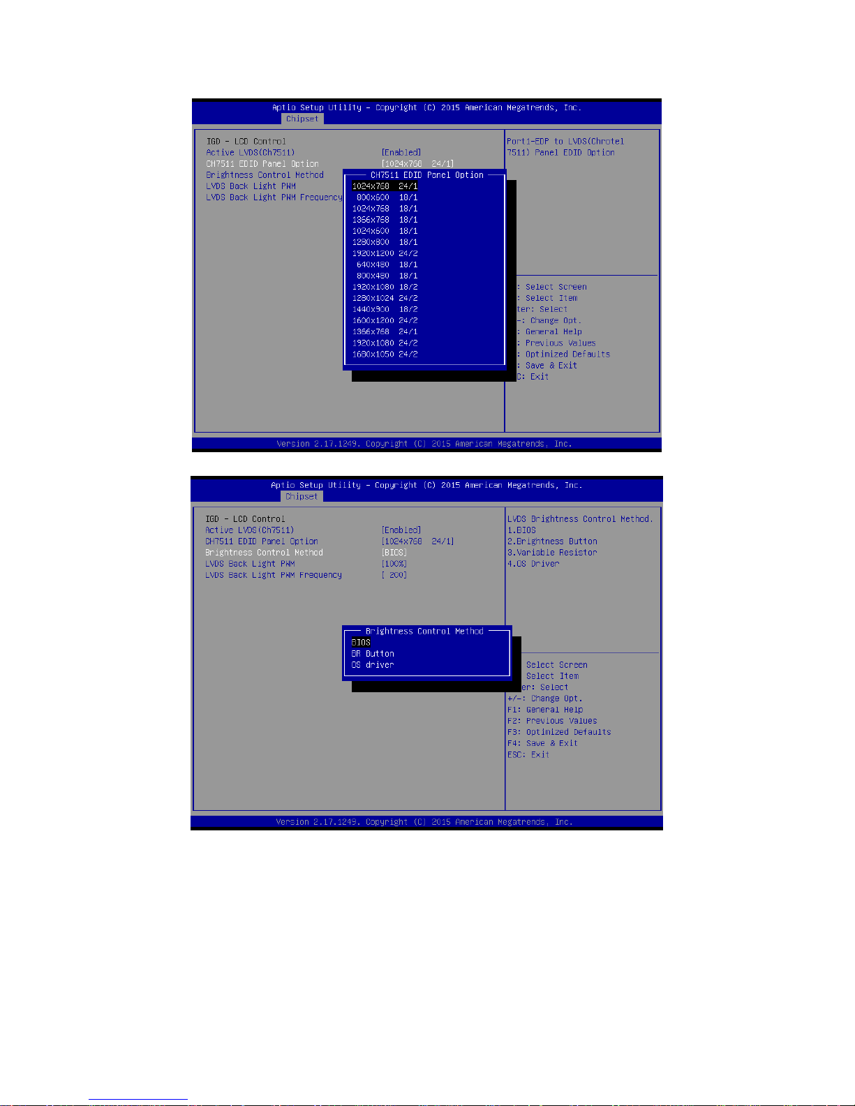
CH7511 EDID Panel Option
1024x768 24/1[Default]
800x600 18/1
1024x768 18/1
Port1-EDP to LVDS (Chrontel 7511) Panel
EDID Option.
Page 88

EMX-BSWP User’s Manual
88 EMX-BSWP User’s Manual
1366x768 18/1
1024x600 18/1
1280x800 18/1
1920x1200 24/2
640x480 18/1
800x480 18/1
1920x1080 18/2
1280x1024 24/2
1440x900 18/2
1600x1200 24/2
1366x768 24/1
1920x1080 24/2
1680x1050 24/2
Brightness Control Method
BIOS[Default]
BR Button
OS driver
LVDS Brightness Control Method. 1.BIOS
2.Brightness Button 3.Variable Resistor.
Note:
BR Button: Must be use FPT-2 Pin4 and
Pin6.
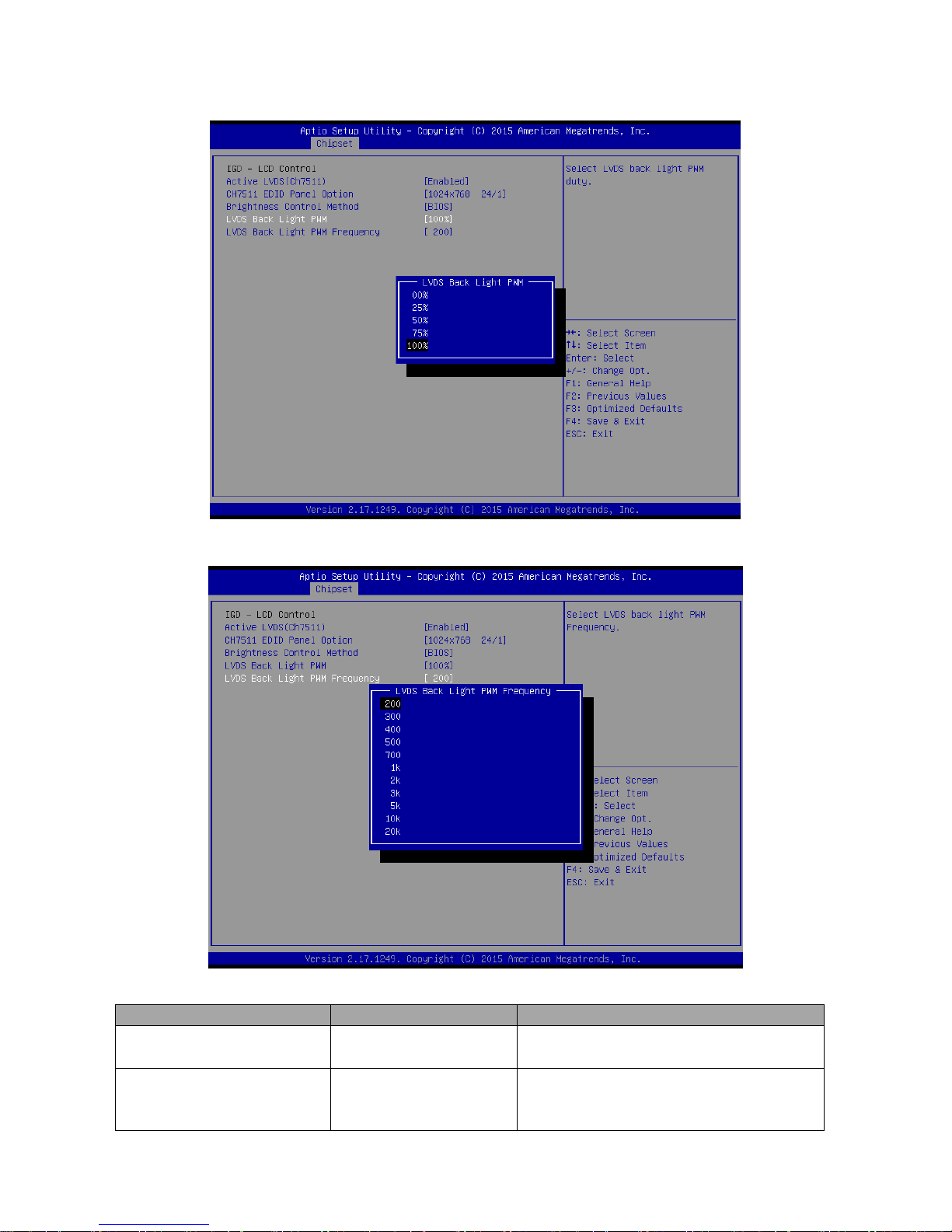
LVDS Back Light PWM
00%
25%
50%
75%
100%[Default]
Select LVDS back light PWM duty.
LVDS Back Light PWM
Frequency
200[Default]
300
400
500
700
1k
2k
3k
5k
10k
20k
Select LVDS back light PWM Frequency.
Page 89
User’s Manual
EMX-BSWP User’s Manual
89
3.6.3.2 South Bridge
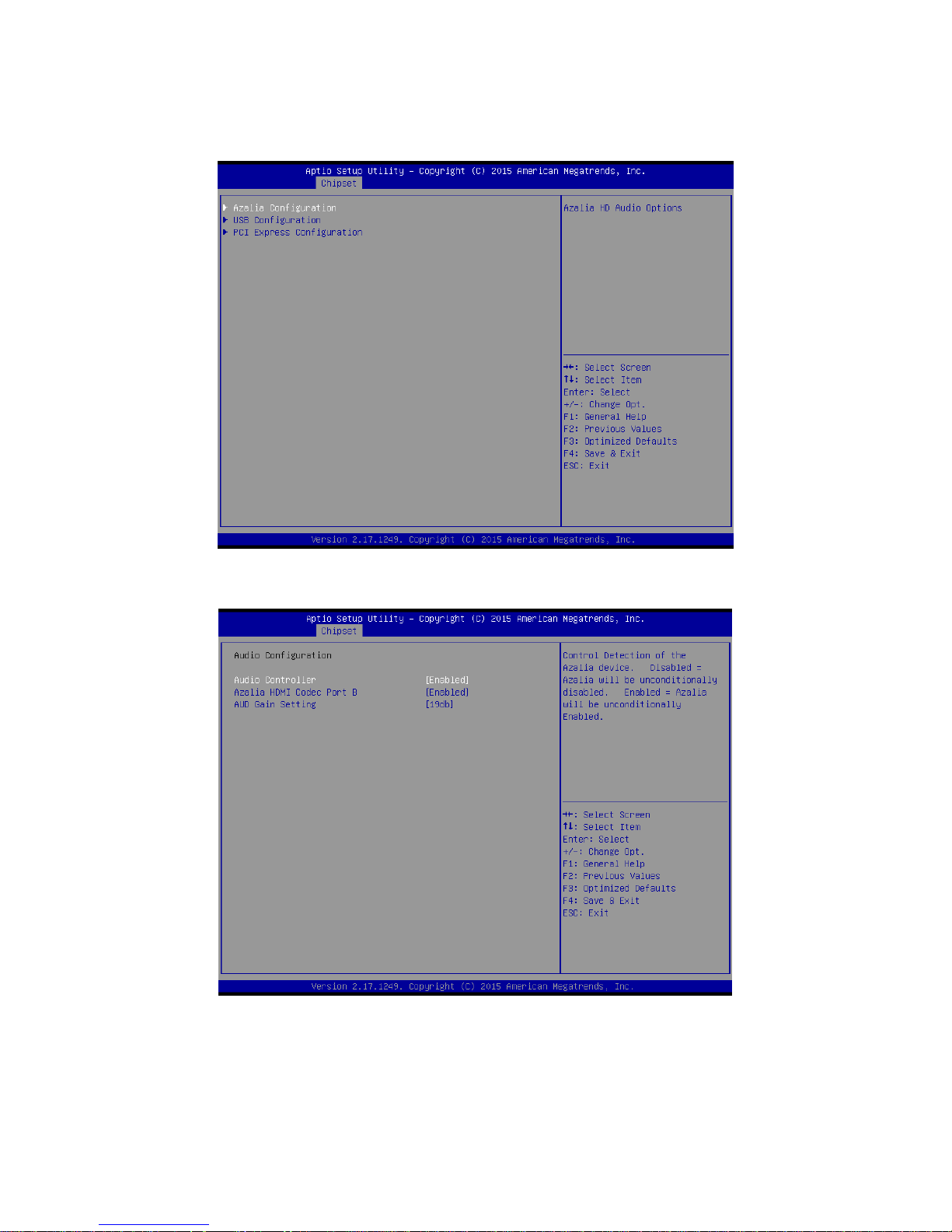
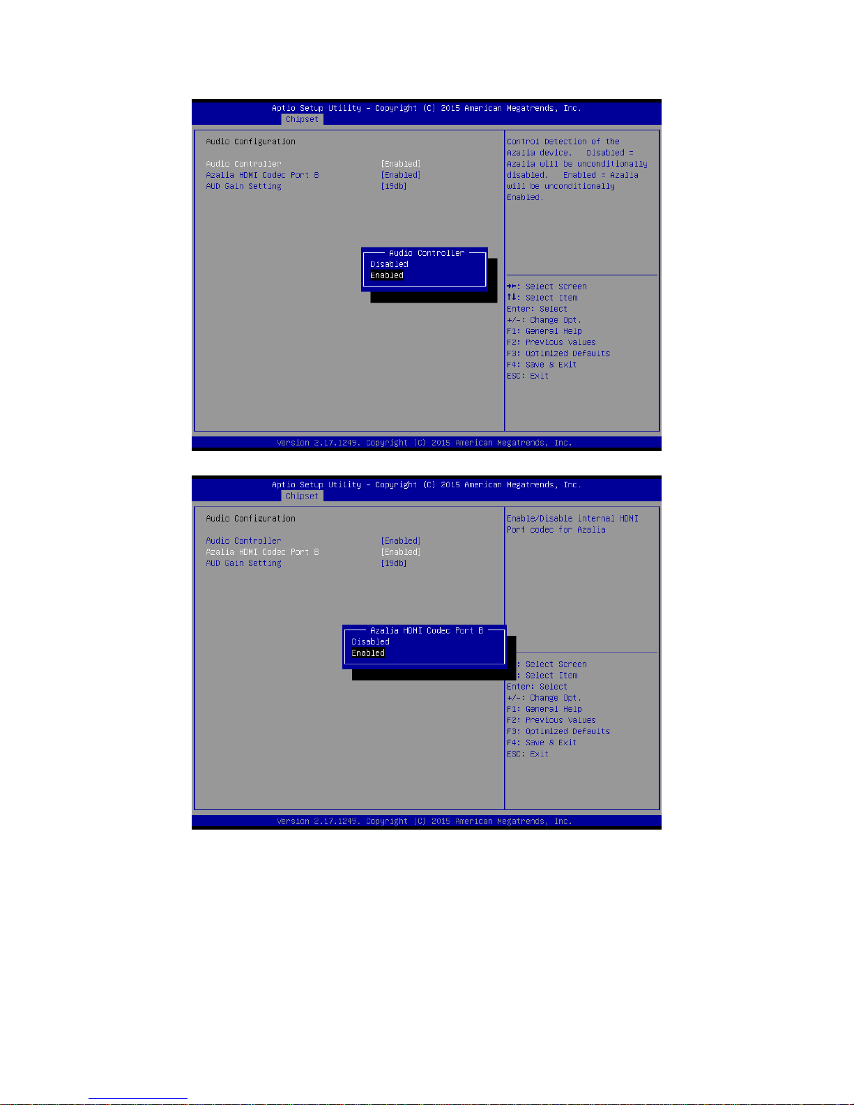
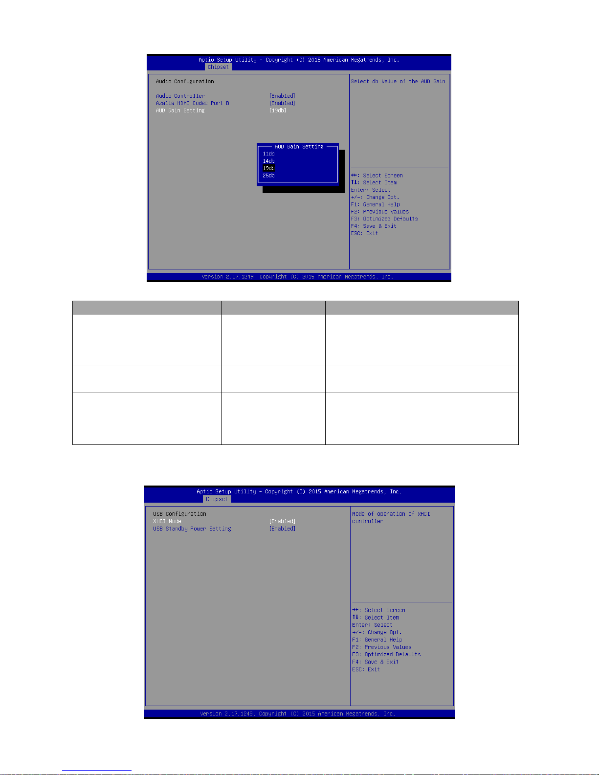
3.6.3.2.1 Azalia Configuration
Page 90
EMX-BSWP User’s Manual
90 EMX-BSWP User’s Manual
Page 91
User’s Manual
EMX-BSWP User’s Manual
91
Item
Option
Description
Audio Controller
Enabled[Default],
Disabled
Control Detection of the Azalia device.
Disabled = Azalia will be unconditionally
disabled. Enabled = Azalia will be
unconditionally Enabled.
Azalia HDMI Codec Port B
Enabled[Default],
Disabled
Enable/Disable HDMI Port codec for Azalia.
AUD Gain Setting
11db
14db
19db[Default]
25db
Select db Value of the AUD Gain.
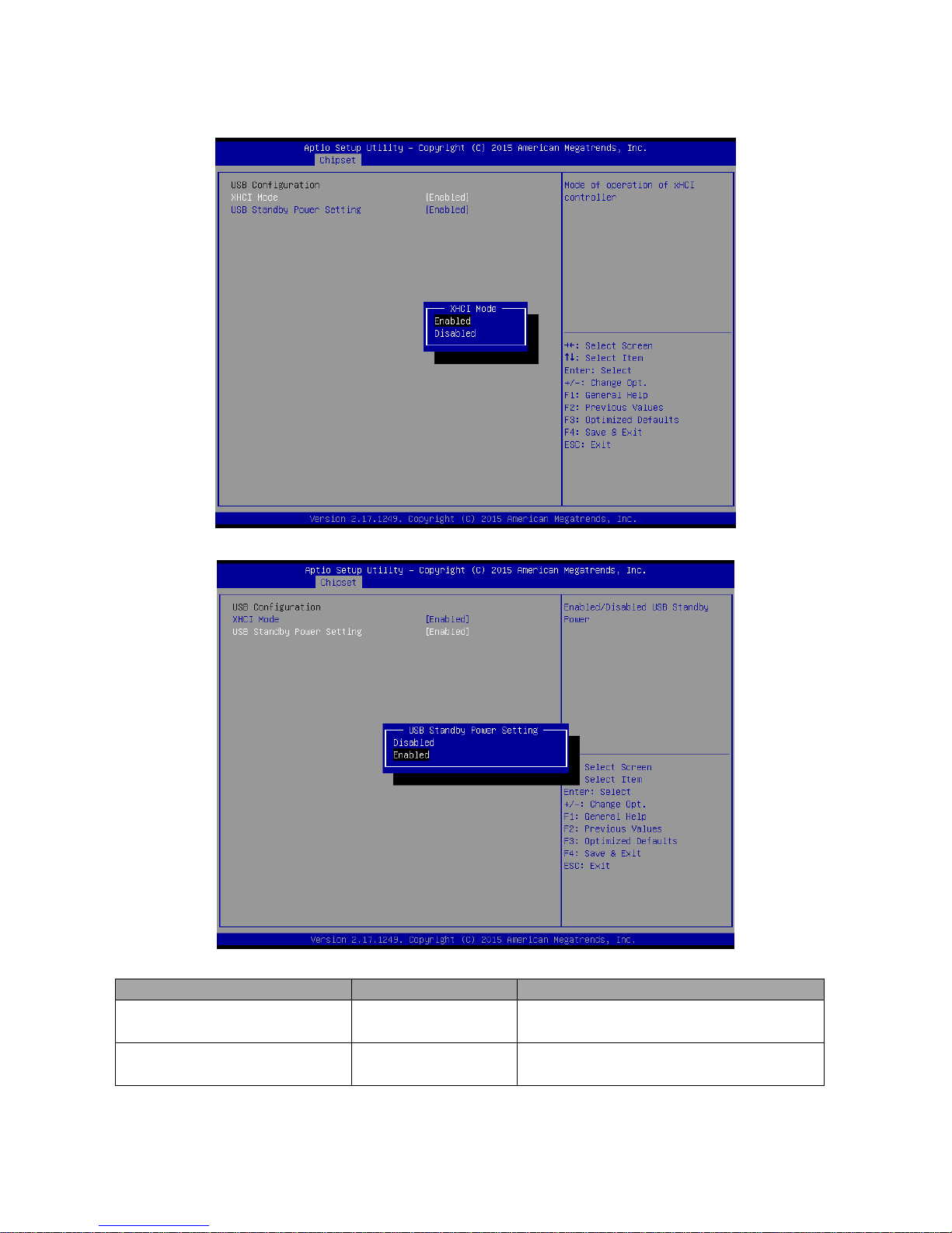
3.6.3.2.2 USB Configuration
Page 92
EMX-BSWP User’s Manual
92 EMX-BSWP User’s Manual
Item
Option
Description
XHCI Mode
Enabled[Default],
Disabled
Mode of operation of xHCI controller.
USB Standby Power Setting
Enabled[Default],
Disabled
Enabled/Disabled USB Standby Power.
Page 93
User’s Manual
EMX-BSWP User’s Manual
93
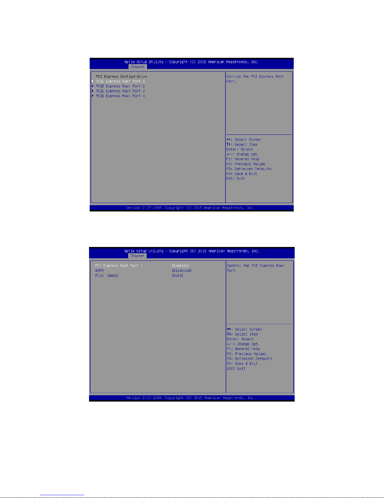
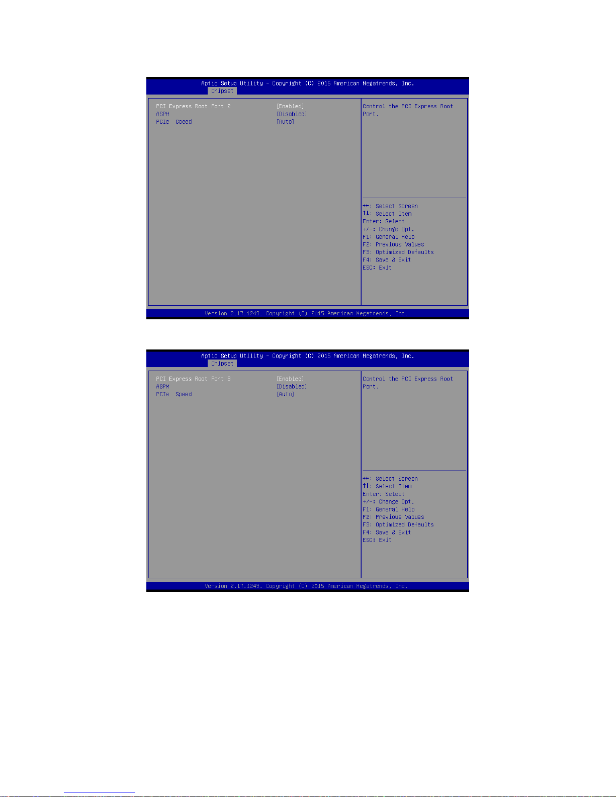
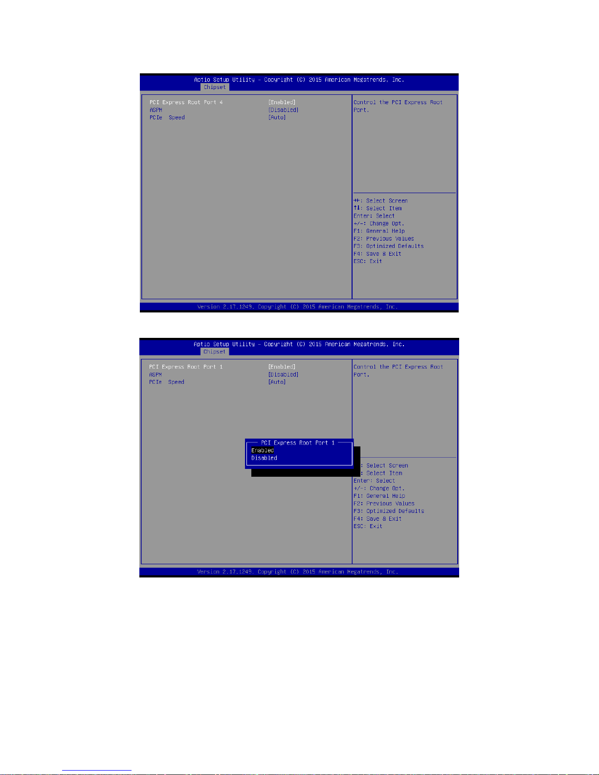
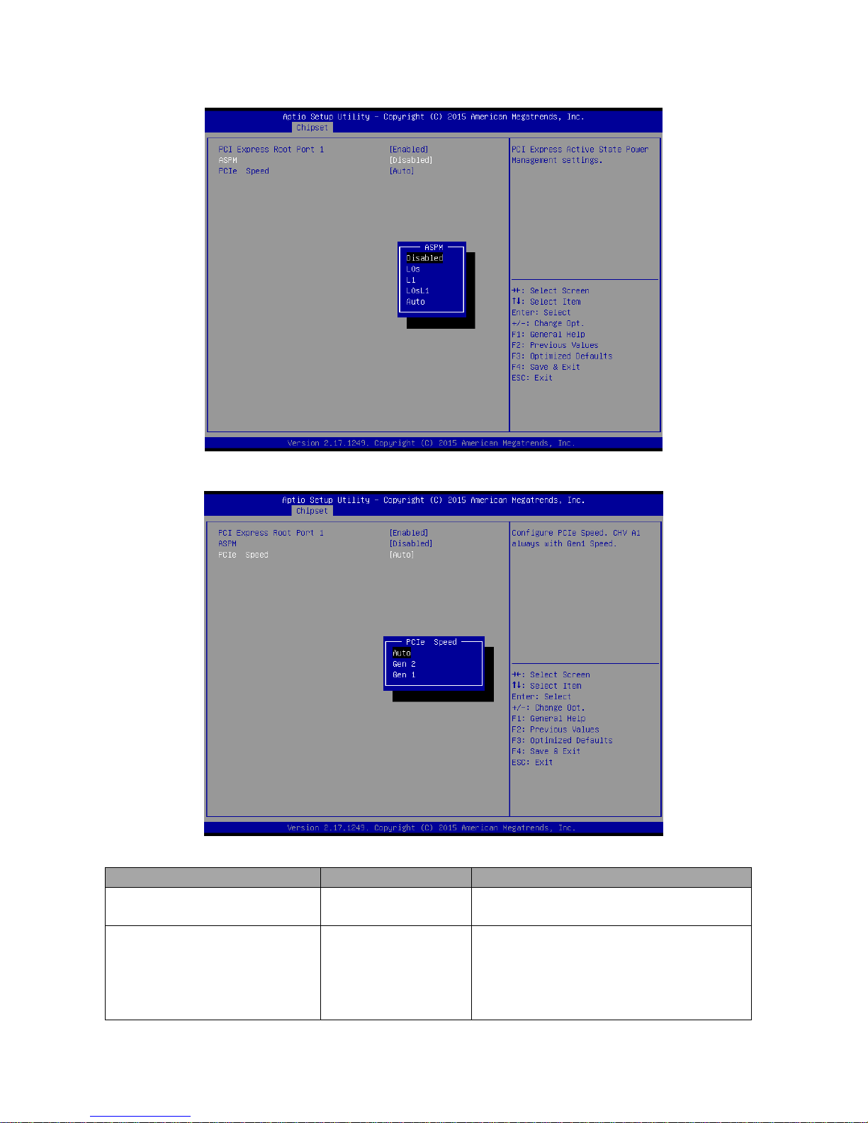
3.6.3.2.3 PCI Express Configuration
3.6.3.2.3.1 PCIE Express Root Port1
Page 94
EMX-BSWP User’s Manual
94 EMX-BSWP User’s Manual
Page 95
User’s Manual
EMX-BSWP User’s Manual
95
Page 96
EMX-BSWP User’s Manual
96 EMX-BSWP User’s Manual
Item
Option
Description
PCI Express Root Port 1/2/3/4
Enabled[Default],
Disabled
Control the PCI Express Root Port.
ASPM
Disabled[Default]
L0s
L1
L0sL1
Auto
PCI Express Active State Power
Management settings.
Page 97
User’s Manual
EMX-BSWP User’s Manual
97
PCIe Speed
Auto[Default]
Gen 2
Gen 1
Configure PCIe Speed. CHV A1 always with
Gen 1 Speed.
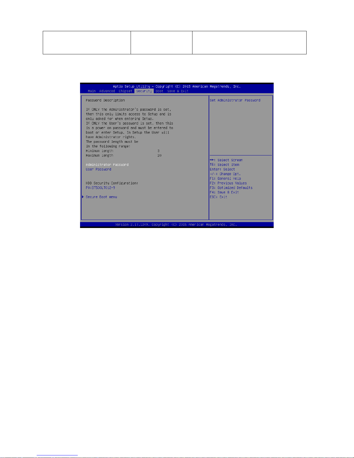
3.6.4 Security
Administrator Password
Set setup Administrator Password
User Password
Set User Password
Page 98
EMX-BSWP User’s Manual
98 EMX-BSWP User’s Manual
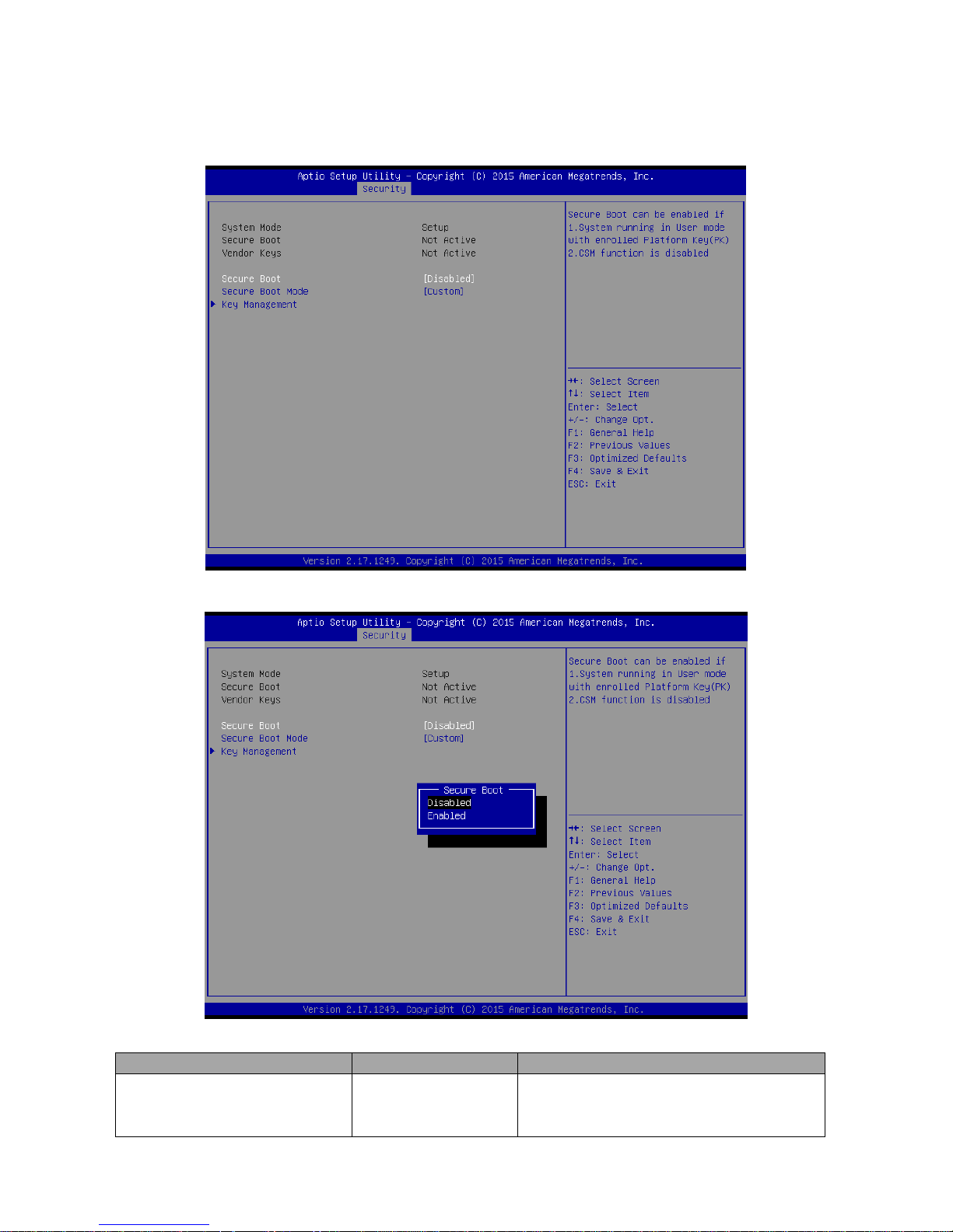
3.6.4.1 Secure Boot menu
Item
Option
Description
Secure Boot
Disabled[Default]
Enabled
Secure Boot can be enabled if 1.System
running in User mode with enrolled Platform
Key(PK) 2.CSM function is disabled.
Page 99
User’s Manual
EMX-BSWP User’s Manual
99
Secure Boot Mode
Standard
Custom[Default]
Secure Boot mode selector. ‘Custom’ Mode
enables users to change Image Execution
policy and manage Secure Boot Keys.
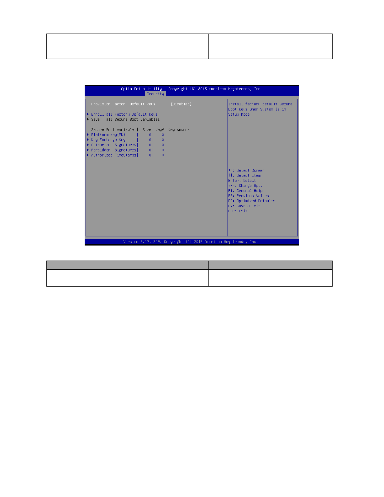
3.6.4.1.1 Key Management
Item
Option
Description
Provision Factory Default Keys
Enabled,
Disabled[Default]
Install Factory default Secure Boot Keys
when System is in Setup Mode.
Page 100
EMX-BSWP User’s Manual
100 EMX-BSWP User’s Manual
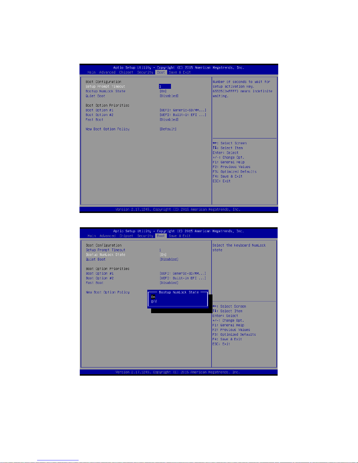
3.6.5 Boot
 Loading...