

Page 1
Part No. E2017XA5500R
EMX-A55E
AMD G-Series™ APU with A55E Controller Hub(FCH)
Mini-ITX Motherboard
Quick Installation Guide
1st Ed –29 June , 2011
Page 2

EMX-A55E
2 EMX-A55E Quick Installation Guide
FCC Statement
THIS DEVICE COMPLIES WITH PART 15 FCC RULES. OPERATION IS
SUBJECT TO THE FOLLOWING TWO CONDITIONS:
(1) THIS DEVICE MAY NOT CAUSE HARMFUL INTERFERENCE.
(2) THIS DEVICE MUST ACCEPT ANY INTERFERENCE RECEIVED INCLUDING
INTERFERENCE THAT MAY CAUSE UNDESIRED OPERATION.
THIS EQUIPMENT HAS BEEN TESTED AND FOUND TO COMPLY WITH THE LIMITS
FOR A CLASS "A" DIGITAL DEVICE, PURSUANT TO PART 15 OF THE FCC RULES.
THESE LIMITS ARE DESIGNED TO PROVIDE REASONABLE PROTECTION AGAINST
HARMFUL INTERFERENCE WHEN THE EQUIPMENT IS OPERATED IN A
COMMERCIAL ENVIRONMENT. THIS EQUIPMENT GENERATES, USES, AND CAN
RADIATE RADIO FREQUENCY ENERGY AND, IF NOT INSTALLED AND USED IN
ACCORDANCE WITH THE INSTRUCTION MANUAL, MAY CAUSE HARMFUL
INTERFERENCE TO RADIO COMMUNICATIONS.
OPERATION OF THIS EQUIPMENT IN A RESIDENTIAL AREA IS LIKELY TO CAUSE
HARMFUL INTERFERENCE IN WHICH CASE THE USER WILL BE REQUIRED TO
CORRECT THE INTERFERENCE AT HIS OWN EXPENSE.
Copyright Notice
Copyright 2011 Avalue Technology Inc., ALL RIGHTS RESERVED.
No part of this document may be reproduced, copied, translated, or transmitted in any form
or by any means, electronic or mechanical, for any purpose, without the prior written
permission of the original manufacturer.
A Message to the Customer
Avalue Customer Services
Each and every Avalue’s product is built to the most exacting specifications to ensure
reliable performance in the harsh and demanding conditions typical of industrial
environments. Whether your new Avalue device is destined for the laboratory or the factory
floor, you can be assured that your product will provide the reliability and ease of operation
for which the name Avalue has come to be known.
Your satisfaction is our primary concern. Here is a guide to Avalue’s customer services. To
ensure you get the full benefit of our services, please follow the instructions below carefully.
Technical Support
We want you to get the maximum performance from your products. So if you run into
technical difficulties, we are here to help. For the most frequently asked questions, you can
Page 3

Quick Installation Guide
EMX-A55E Quick Installation Guide 3
easily find answers in your product documentation. These answers are normally a lot more
detailed than the ones we can give over the phone. So please consult the user’s manual
first.
To receive the latest version of the user’s manual; please visit our Web site at:
http://www.avalue.com.tw/
If you still cannot find the answer, gather all the information or questions that apply to your
problem, and with the product close at hand, call your dealer. Our dealers are well trained
and ready to give you the support you need to get the most from your Avalue’s products. In
fact, most problems reported are minor and are able to be easily solved over the phone.
In addition, free technical support is available from Avalue’s engineers every business day.
We are always ready to give advice on application requirements or specific information on
the installation and operation of any of our products. Please do not hesitate to call or e-mail
us.
Headquarters and Branch
Avalue USA
Avalue Technology Inc.
7F, 228, Lian-cheng Road, Chung Ho City, Taipei,
Taiwan
Tel:+886-2-8226-2345
Fax: +886-2-8226-2777
Information:[email protected]
Service: [email protected]
Avalue Technology Inc.
9 Timber Lane, Marlboro, NJ 07746-1443
Tel: (732) 414-6500
Fax: (732) 414-6501
Information: [email protected]
Service: [email protected]
BCM Advanced Research
Avalue Europe
BCM Advanced Research
an Avalue Company
7 Marconi, Irvine, CA92618
Tel: +1-949-470-1888
Fax: +1-949-470-0971
Information: [email protected]
Web: www.bcmcom.com
Avalue Europe A/S
Moelledalen 22C, 3140
Aalsgaarde, Denmark
Tel: +45-7025-0310
Fax:+45-4975-5026
Information: [email protected]
Service: [email protected]
Avalue China
Avalue Japan
Avalue Technology Inc.
Room 805, Building 9,No.99 Tianzhou Rd.,
Caohejing Development Area,
Xuhui District, Shanghai
Tel: +86-21-5169-3609
Fax:+86-21-5445-3266
Information: [email protected]
Service: [email protected]
Avalue Technology Inc.
2F keduka-Bldg, 2-27-3 Taito,
Taito-Ku, Tokyo 110-0016 Japan
Tel: +81-3-5807-2321
Fax: +81-3-5807-2322
Information: [email protected]
Service: [email protected]
Page 4
EMX-A55E
4 EMX-A55E Quick Installation Guide
1. Getting Started
1.1 Safety Precautions
Warning!
Always completely disconnect the power cord from your
chassis whenever you work with the hardware. Do not
make connections while the power is on. Sensitive
electronic components can be damaged by sudden power
surge. Only experienced electronics personnel should open
the PC chassis.
Caution!
Always ground yourself to remove any static charge before
touching the CPU card. Modern electronic devices are very
sensitive to static electric charges. As a safety precaution,
use a grounding wrist strap at all times. Place all electronic
components in a static-dissipative surface or static-shielded
bag when they are not in the chassis.
Always note that improper disassembling could damage to the
motherboard. We suggest not to, in any circumstance remove the heatsink
without the correct instructions. If you really have to do it, please contact us
for further support.
1.2 Packing List
Before you begin installing your single board, please make sure that the
following items have been shipped:
1 x EMX-A55E Mini ITX Main board
1 x CD-ROM contains OS drivers
1 x CPU Cooler
1 x SATA cable
1 x I/O Shield
1 x Startup Manual
Page 5
Quick Installation Guide
EMX-A55E Quick Installation Guide 5
2. Hardware
Configuration
Page 6
EMX-A55E
6 EMX-A55E Quick Installation Guide
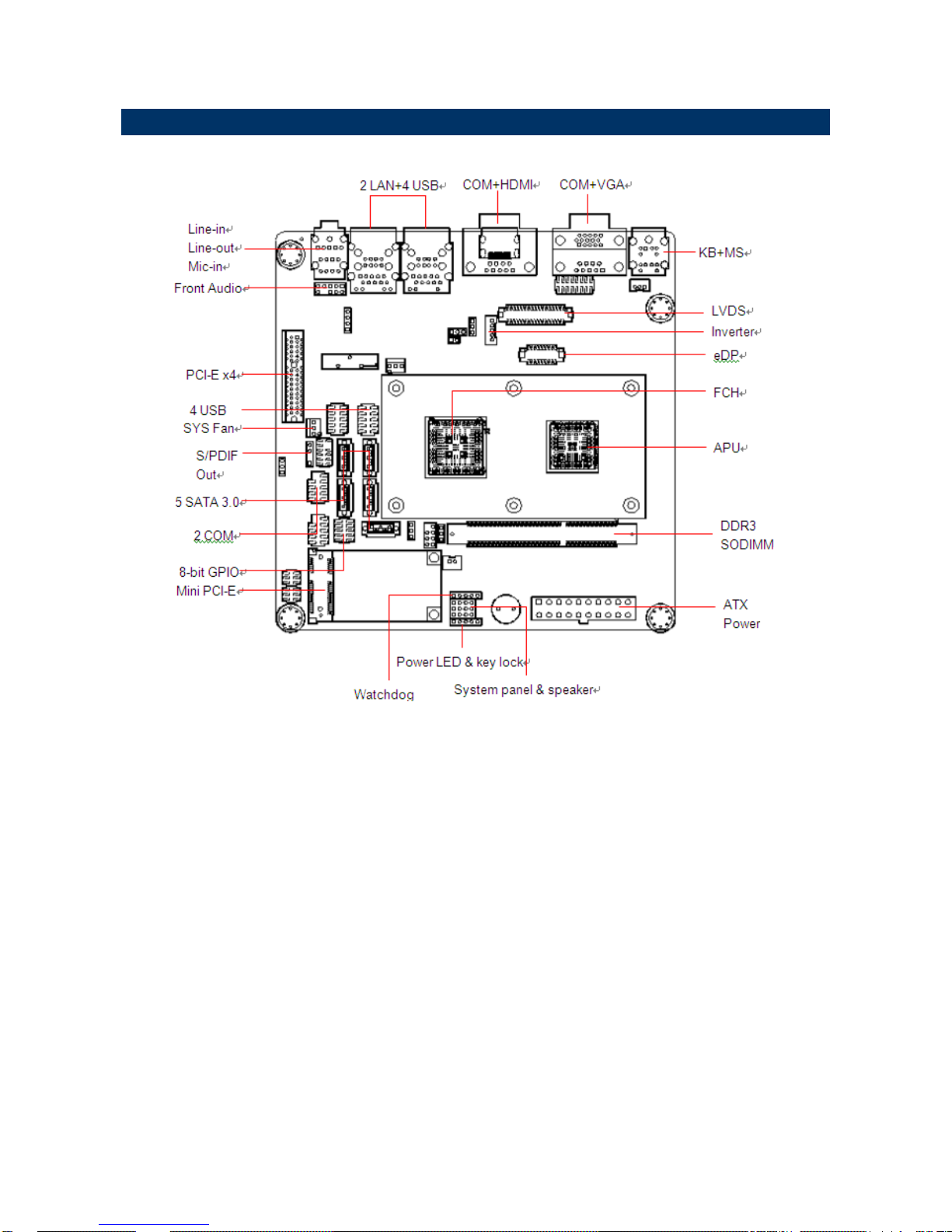
2.1 Product Overview
Page 7
Quick Installation Guide
EMX-A55E Quick Installation Guide 7
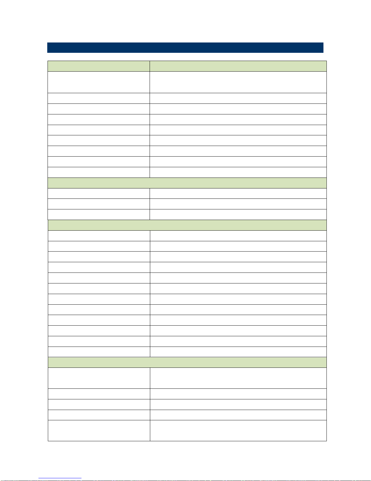
2.1 Specifications
APU
G-Series
APU Type
AMD G-Series T56N 1.6GHz DC /T40N 1.0GHz DC
Processor Family
AMD G-Series
Long Life Processor List
TDP 5~18W, T shutdown 125℃
Package
FT1 (BGA) 413 balls p=0.8mm, 19x19 mm
L2 Cache
L1: 32KB+32KB per core, L2: 512KB cache per core
UMI
4-Lane(x4) PCIe gen2
Power Management
C6 supported
PCIE
4-Lane(x4) PCIe gen2
CPU Process
40 nm
System Memory
Memory Type
One DDR3 1066 SODIMM
DIMM #
1x SODIMM 204Pin/ Single Channel
Max. Capacity
4 GB
Chipset
FCH
Fusion Controller Hub
AMD A55E Controller Hub (Hudson-E1)
PCIe
x4 Gen 2
USB
8 USB 2.0 (4 Rear, 4 Internal)
SMBus
Yes
LPC
Yes
SATA
5 SATA 3.0 (One support SATADOM)
PCI
N/A
HD Audio
support 4 channel, Power Saving, 4 codec
Clock Gen.
Integrated
Package
FCBGA 23x23mm, 605 balls
Environment
TDP 2.7~5.7W, T case 105℃
Display
Integrated Graphic Controller
ATI Radeon™ HD 6320 (T56N)/ HD 6290 (T40N) Graphics Engine
supports
HW decoder
H.264, VC-1, MPEG-2 and DivX decode
3D feature
DirectX 11, OpenGL 4.0, dedicated hardware (UVD 3.0)
LVDS
1, 18bpp (Single link LVDS up to 1400 x 1050)
VGA
T56N (18W) supports up to 2560 x 1600
T40N (9W) supports up to 1920 x 1200
Page 8
EMX-A55E
8 EMX-A55E Quick Installation Guide
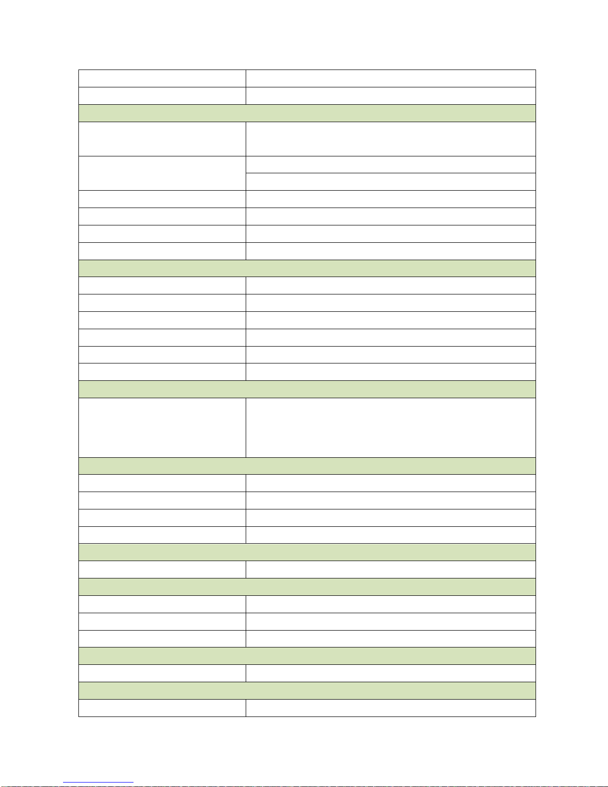
HDMI
1 support HDMI 1.3a & 1080p up to 1920 x 1080
Dual Display
VGA+LVDS, VGA+HDMI, HDMI+LVDS
Gigabit Ethernet
Chipset
LAN1 RTL 8111DL Gigabit LAN
LAN2 RTL 8111DL Gigabit LAN
LAN LED
Left: Link (Off)/ Active (Flash Yellow)
Right: 1Gbps(Green) / 100Mbps (Orange) / 10Mbps (Off)
Disable LAN through BIOS
Yes
WOL
Yes
Boot from LAN
Yes
ASF
N/A
Audio
Codec
7.1 Channel HD Audio
Chipset
Realtek ALC892
Audio output header
Yes, Front Audio Pin Header
Front IO Connector
Stack Phone Jack (Mic In, Line-out, Line-in)
SPDI/F
Yes
Amplifier
TI TPA3005
RS232 COM
LPC to COM
2 COM for Rear I/O D-Sub
2 COM with headers
Super I/O
Chipset
Winbond W83627DHG-P
Fan speed monitor & control
FAN Speed Control by Thermal Sensor
Temperature
Yes
Voltage
3.3V, +5V, 5Vsb, +12V, -12V
Buzzer
Onboard buzzer
Yes
WDT
Watchdog Timer
Programmable 1~255 sec/min
TPM
TPM
Onboard TPM1.1/1.2 By Infineon SLB9635 (Optional)
BIOS
BIOS Core
AMI EFI
BIOS Flash
BIOS Flash
16Mb SPI
Page 9
Quick Installation Guide
EMX-A55E Quick Installation Guide 9
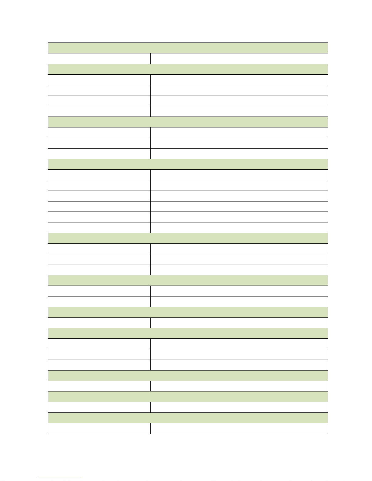
SW RAID
SW RAID
None
Bootup Device
Serial ATA
Yes (CFast)
IDE device
N/A
USB device
Yes
Boot from LAN
Yes
Power Management
ACPI
ACPI 3.0
APM
NA
Sleep State
S3, S4, S5
Other Feature
PC Health
YES
CMOS backup
BIOS CMOS automatic backup and restore setup data
SmartFAN
CPU, SYS FAN, Smart Fan III+
Graphics memory mode
Shared Memory up to 2GB
Power Play
380, 200MHz, configure Power to 2.7~5.7W
SATA
Support SATA III(6Gbps)
Internal Connector
Debug Port
CPU
HDT header
SPI 1 Display
LVDS
1
eDP
1, (optional)
Inverter
LVDS INV
3.3 V
Audio
Front Panel
1
Amplifier
1
SPDI/F
1
USB
USB 4 Serial
COM
2
IDE
IDE
NA
Page 10
EMX-A55E
10 EMX-A55E Quick Installation Guide
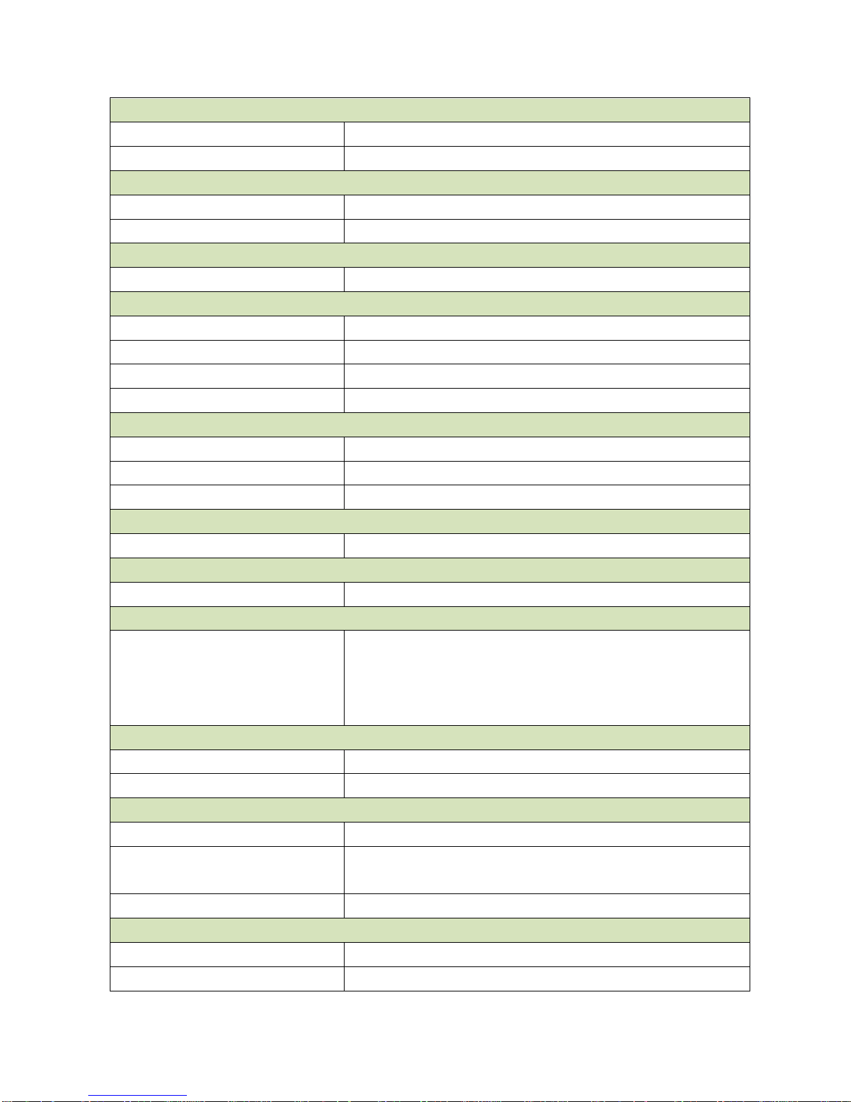
SATA
SATA
5 (SATA III 6 Gb/s)
SATA power
NA
Fan connector
System fan connector
1 system fan(3pin for system with smart fan control)
CPU fan connector
1 CPU fan(3pin for system with smart fan control)
GPIO
General
8bit
Front I/O
Display
HDMI
1
VGA
1, co-layout with header
DVI
NA
Ethernet
RJ-45
2, stack with USB
USB
USB
4 (USB 2.0 port)
COM
Serial port
2* RS-232
PS/2
KB/MS
2, co-lay single DIN
Audio
Phone Jack
1 Line-in
1 Line-out
1 MIC
co-lay 1 jack connector
Power Connector
Power Type
AT/ATX
Power Requirement
+3.3V, +5V, +12V, -12V, 5Vsb
LED Indicator
LED
HDD Status
4; alive, green; dead, red
4; access, flash yellow
Power on rear IO
1; Blue
Expansion Slot
Mini-PCI Express
1
PCIex 4
1
Page 11

Quick Installation Guide
EMX-A55E Quick Installation Guide 11
PCB Physical Feature
Dimension
170x 170mm
Layer
6 Layer
Power Consumption
< 45W
Operating Temperature
0℃-60℃
Heat Sink
Cooler FAN (T56N)
Heatsink (T40N)
Storage Temperature
-20℃ ~ 80℃
Vibration (non OP)
3.5 Grms, heat sink backplane TBD
PCB Printing
Model name in silkscreen
None
Revision in silkscreen
No
PCB Color
Blue
CE mark on PCB
Yes
WEEE
Yes
Advansus PCB part number
Yes
Version
No
FCC mark on PCB
Yes
Cert. Compliance
CE
Pre-scan for Class B, EN-55022/24
FCC
Pre-scan for FCC PART 15, Class B
IEC-60601
compliance
Accessory
Accessory List
FP_USB cable
None
SATA cable Kit
1 data and 1 power
Serial Port
2
I/O Shield
1
Driver CD
1
Startup Manual
None
FP_Power button, power LED, HDD LED kit
None
AVL
OS Support List
Windows XP SP3, Windows 7 Pro, Linux Fedora 14
Page 12
EMX-A55E
12 EMX-A55E Quick Installation Guide
2.2 Jumper and Connector List
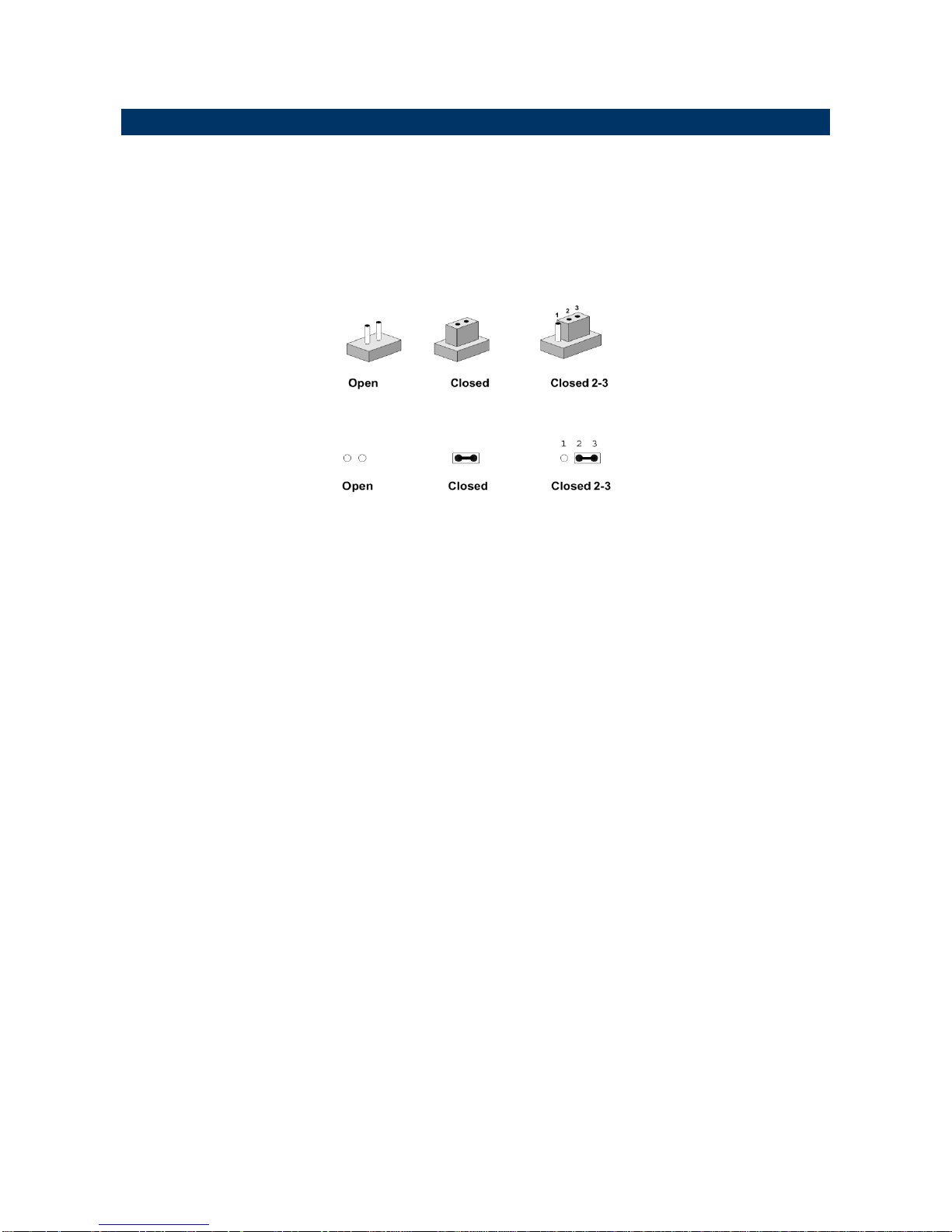
You can configure your board to match the needs of your application by setting jumpers. A
jumper is the simplest kind of electric switch.
It consists of two metal pins and a small metal clip (often protected by a plastic cover) that
slides over the pins to connect them. To “close” a jumper you connect the pins with the clip.
To “open” a jumper you remove the clip. Sometimes a jumper will have three pins, labeled 1,
2, and 3. In this case, you would connect either two pins.
The jumper settings are schematically depicted in this manual as follows:
A pair of needle-nose pliers may be helpful when working with jumpers.
Connectors on the board are linked to external devices such as hard disk drives, a
keyboard, or floppy drives. In addition, the board has a number of jumpers that allow you to
configure your system to suit your application.
If you have any doubts about the best hardware configuration for your application, contact
your local distributor or sales representative before you make any changes.
Page 13
Quick Installation Guide
EMX-A55E Quick Installation Guide 13
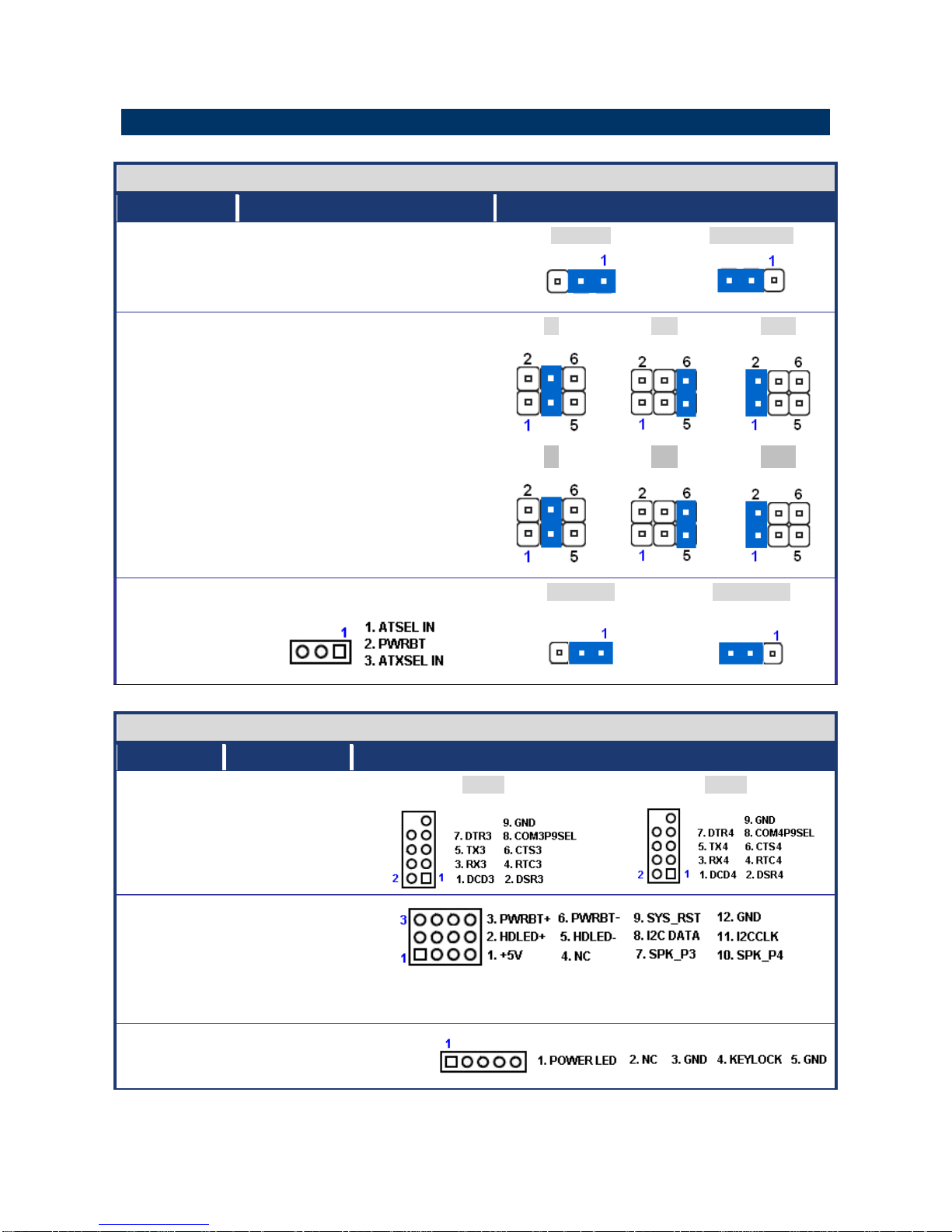
2.1 Setting Jumpers & Connectors
Jumpers
Label
Function
Note
CMOS1
Clear CMOS
Normal *
Clear CMOS
JSETCOM3,
JSETCOM4
COM3, COM4 RI/+5V/+12V Select
RI
+5V
+12V
COM3
COM4
RI
+5V
+12V
PSON1
AT/ATX Mode Select
AT MODE
ATX MODE
Connectors
Label
Function
Note
COM3, COM4
Serial Port
Connector
COM3
COM4
JFP1+JFP2
System Panel &
Speaker
PIN7-10
PIN1-10
SPK3
SPK4
PIN3-6
PIN9-12
POWER BT
SYS_RESET
JFP3
Power LED &
Keylock
Page 14
EMX-A55E
14 EMX-A55E Quick Installation Guide
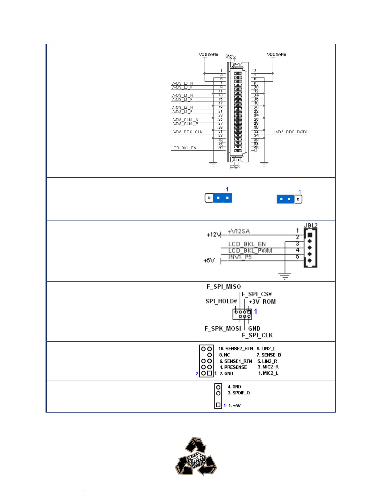
LVDS1
18-bit LVDS
Connector
JBL3
LCD POWER
(VDDSAFE )
3.3V/5V
SELECTION
3.3V 5V
JBL1
Inverter PWR
JBL1
LCD Inverter
Connector
AAFP
Audio Mic.-In &
Line-Out
Connector
SPDIF_OUT1
SPDIF OUT
 Loading...