

Page 1

EMS-SKLU/
EMS-SKLU-Marine
6th Gen Intel® Core™ Processor i7/i5/i3/Celeron Fanless
Rugged Embedded System
Quick Reference Guide
1st Ed –01 March 2017
Copyright Notice
Copyright 2017 Avalue Technology Inc., ALL RIGHTS RESERVED.
Part No. E2017AAG0A1R
Page 2

EMS-SKLU/EMS-SKLU-Marine
FCC Statement
A Message to the Customer
THIS DEVICE COMPLIES WITH PART 15 FCC RULES. OPERATION IS
SUBJECT TO THE FOLLOWING TWO CONDITIONS:
(1) THIS DEVICE MAY NOT CAUSE HARMFUL INTERFERENCE.
(2) THIS DEVICE MUST ACCEPT ANY INTERFERENCE RECEIVED INCLUDING
INTERFERENCE THAT MAY CAUSE UNDESIRED OPERATION.
THIS EQUIPMENT HAS BEEN TESTED AND FOUND TO COMPLY WITH THE LIMITS
FOR A CLASS "A" DIGITAL DEVICE, PURSUANT TO PART 15 OF THE FCC RULES.
THESE LIMITS ARE DESIGNED TO PROVIDE REASONABLE PROTECTION AGAINST
HARMFUL INTERFERENCE WHEN THE EQUIPMENT IS OPERATED IN A
COMMERCIAL ENVIRONMENT. THIS EQUIPMENT GENERATES, USES, AND CAN
RADIATE RADIO FREQUENCY ENERGY AND, IF NOT INSTATLLED AND USED IN
ACCORDANCE WITH THE INSTRUCTION MANUAL, MAY CAUSE HARMFUL
INTERFERENCE TO RADIO COMMUNICATIONS.
OPERATION OF THIS EQUIPMENT IN A RESIDENTIAL AREA IS LIKELY TO CAUSE
HARMFUL INTERFERENCE IN WHICH CASE THE USER WILL BE REQUIRED TO
CORRECT THE INTERFERENCE AT HIS OWN EXPENSE.
Avalue Customer Services
Each and every Avalue’s product is built to the most exacting specifications to ensure
reliable performance in the harsh and demanding conditions typical of industrial
environments. Whether your new Avalue device is destined for the laboratory or the factory
floor, you can be assured that your product will provide the reliability and ease of operation
for which the name Avalue has come to be known.
Your satisfaction is our primary concern. Here is a guide to Avalue’s customer services. To
ensure you get the full benefit of our services, please follow the instructions below carefully.
Technical Support
We want you to get the maximum performance from your products. So if you run into
technical difficulties, we are here to help. For the most frequently asked questions, you can
easily find answers in your product documentation. These answers are normally a lot more
detailed than the ones we can give over the phone. So please consult the user’s manual
first.
To receive the latest version of the user’s manual; please visit our Web site at:
http://www.avalue.com.tw/
2 EMS-SKLU/EMS-SKLU-Marine Quick Reference Guide
Page 3

Quick Reference Guide
3
Content
1. Getting Started .............................................................................................................. 7
1.1 Safety Precautions ................................................................................................ 7
1.2 Packing List ........................................................................................................... 7
1.3 System Specifications ........................................................................................... 8
1.4 System Overview ................................................................................................. 11
1.4.1 Front View .................................................................................................................................. 11
1.4.2 Rear View ................................................................................................................................... 12
1.5 System Dimensions ............................................................................................. 13
1.5.1 EMS-SKLU Front & Top view .................................................................................................... 13
1.5.2 EMS-SKLU-Marine Front & Top view ........................................................................................ 14
2. Hardware Configuration .............................................................................................. 15
2.1 EMS-SKLU connector mapping ........................................................................... 16
2.1.1 Serial port connector 1 (COM1) ................................................................................................. 16
2.1.2 Serial port connector 3/4/5/6 (COM3/4/5/6) ............................................................................... 16
2.1.3 Multi-Function Port combined COM2, 2 PS/2, Audio, GPIO and SMBus (Multi-function port) . 17
2.1.3.1 GPIO+SMBUS ....................................................................................................................... 18
2.1.3.2 COM2 .................................................................................................................................... 18
2.2 EBM-SKLUS, AUX-M01, AUX-M02, AUX-M03, AUX-M04, AUX-M07, EBM-BYTS
DB-A and EBM-CDVS DB-A Overviews ......................................................................... 19
2.2.1 EBM-SKLUS .............................................................................................................................. 19
2.2.2 AUX-M01 .................................................................................................................................... 20
2.2.3 AUX-M02 .................................................................................................................................... 20
2.2.4 AUX-M03 .................................................................................................................................... 21
2.2.5 AUX-M04 .................................................................................................................................... 22
2.2.6 AUX-M07 .................................................................................................................................... 22
2.2.7 EBM-BYTS DB-A ....................................................................................................................... 23
2.2.8 EBM-CDVS DB-A ...................................................................................................................... 23
2.2.9 EBM-CDVS DB-B ...................................................................................................................... 24
2.3 EBM-SKLUS Jumper & Connector list ................................................................. 25
2.4 EBM-SKLUS Jumpers & Connectors settings ..................................................... 27
2.4.1 Multi-function select (SW1) ........................................................................................................ 27
2.4.2 COM 1/2 pin 9 signal select (JRI1/2) ......................................................................................... 28
2.4.3 Serial port 1/2 RS-232/422/485 mode select (JCOM_SEL1/2) ................................................. 28
2.4.4 Clear CMOS (JCMOS1) ............................................................................................................. 29
2.4.5 LPC port connector (JLPC1) ...................................................................................................... 29
EMS-SKLU/EMS-SKLU-Marine Quick Reference Guide
Page 4

EMS-SKLU/EMS-SKLU-Marine
2.4.6 SPI connector (JSPI1) ............................................................................................................... 30
2.4.7 Front Panel Connector (CN5) .................................................................................................... 30
2.4.8 DC Output connector (DCOUT1) ............................................................................................... 31
2.4.9 DC Input connector (JVIN1) ....................................................................................................... 31
2.4.10 EC Debug connector (JEC_ROM1)....................................................................................... 32
2.4.11 On-board header for USB2.0 (USB2) .................................................................................... 32
2.4.12 Power ON/OFF connector (PWRBTN1) ................................................................................ 33
2.5 AUX-M01, AUX-M02, AUX-M03, AUX-M04, AUX-M07, EBM-BYTS DB-A ,
EBM-CDVS DB-A and EBM-CDVS DB-B Jumper & Connector list ............................... 34
2.6 AUX-M01 Jumpers & Connectors settings .......................................................... 37
2.6.1 COM 3/4/5/6 pin 9 signal select (JRI3/4/5/6) ............................................................................. 37
2.6.2 USB connector (USB3) .............................................................................................................. 37
2.6.3 USB connector (JUSB3) ............................................................................................................ 38
2.6.4 SMBUS of TCA9555 address setting (PJP1) ............................................................................ 38
2.7 AUX-M02 Connectors settings ............................................................................ 39
2.7.1 LAN ACT/LNK/SPD LED (JLANLED) ........................................................................................ 39
2.7.2 Normal/Bypass mode LED (JLANMODE) ................................................................................. 39
2.8 AUX-M03 Connectors settings ............................................................................ 40
2.8.1 System reset (WCN1) ................................................................................................................ 40
2.8.2 LPT Port (WJPRT1) ................................................................................................................... 40
2.9 AUX-M04 Jumpers & Connectors settings .......................................................... 41
2.9.1 Operating Modes select (ZJP1) ................................................................................................. 41
2.9.2 Power connector (ZPWR1) ........................................................................................................ 41
2.9.3 LAN ACT/LNK/SPD LED (Z_JLANLED) .................................................................................... 42
2.10 AUX-M07 Connector settings .............................................................................. 43
2.10.1 SMBUS of TCA9555 address setting (SJP2) ........................................................................ 43
2.11 EBM-BYTS DB-A Jumpers & Connectors settings .............................................. 44
2.11.1 COM 3/4 pin 9 signal select (OJRI3/4) .................................................................................. 44
2.11.2 Serial port 1/ 2 – RS485 mode select (OJP485) ................................................................... 44
2.11.3 SMBUS of TCA9555 address setting (OJP1) ........................................................................ 45
2.12 EBM-CDVS DB-A Connector settings ................................................................. 46
2.12.1 Front Panel Connector 1 (CN1) ............................................................................................. 46
2.13 EBM-CDVS DB-B Connector settings ................................................................. 47
2.13.1 DC Input connector (DC-IN1) ................................................................................................ 47
2.13.2 DC Output connector (DC-OUT1) ......................................................................................... 47
2.14 Installing Hard Disk & Memory, PCI devices (EMS-SKLU) .................................. 48
2.15 Installing Mounting Brackets (EMS-SKLU) .......................................................... 49
3.BIOS Setup ..................................................................................................................... 50
3.1 Introduction .......................................................................................................... 51
3.2 Starting Setup ...................................................................................................... 51
4 EMS-SKLU/EMS-SKLU-Marine Quick Reference Guide
Page 5

Quick Reference Guide
5
3.3 Using Setup ......................................................................................................... 52
3.4 Getting Help......................................................................................................... 53
3.5 In Case of Problems ............................................................................................ 53
3.6 BIOS setup .......................................................................................................... 54
3.6.1 Main Menu ................................................................................................................................. 54
3.6.1.1 System Language ............................................................................................................................ 55
3.6.1.2 System Date .................................................................................................................................... 55
3.6.1.3 System Time .................................................................................................................................... 55
3.6.2 Advanced Menu ......................................................................................................................... 55
3.6.2.1 Trusted Computing .......................................................................................................................... 56
3.6.2.2 ACPI Settings .................................................................................................................................. 57
3.6.2.3 AMT Configuration ........................................................................................................................... 58
3.6.2.4 PCH-FW Configuration .................................................................................................................... 59
3.6.2.4.1 Firmware Update Configuration ................................ ....................................................................... 59
3.6.2.5 IT8528 Super IO Configuration ........................................................................................................ 60
3.6.2.5.1 Serial Port 1 Configuration ............................................................................................................... 60
3.6.2.5.2 Serial Port 2 Configuration ............................................................................................................... 61
3.6.2.6 EC 8528 H/W Monitor ...................................................................................................................... 61
3.6.2.7 S5 RTC Wake Settings .................................................................................................................... 62
3.6.2.8 Serial Port Console Redirection ....................................................................................................... 62
3.6.2.8.1 Legacy Console Redirection Settings .............................................................................................. 63
3.6.2.9 CPU Configuration ........................................................................................................................... 64
3.6.2.10 Intel TXT Information ....................................................................................................................... 64
3.6.2.11 SATA Configuration ......................................................................................................................... 65
3.6.2.12 Network Stack Configuration ........................................................................................................... 66
3.6.2.13 CSM Configuration........................................................................................................................... 66
3.6.2.14 USB Configuration ........................................................................................................................... 67
3.6.3 Chipset ..................................................................................................................................... 68
3.6.3.1 System Agent (SA) Configuration .................................................................................................... 68
3.6.3.1.1 Graphics Configuration .................................................................................................................... 69
3.6.3.1.2 Memory Configuration ...................................................................................................................... 69
3.6.3.2 PCH-IO Configuration ...................................................................................................................... 70
3.6.3.2.1 PCI Express Configuration ............................................................................................................... 70
3.6.3.2.1.1 PCI Express Root Port2 (mPCIe) ............................................................................................ 71
3.6.3.2.1.2 PCI Express Root Port3 (I210/211) ......................................................................................... 72
3.6.3.2.1.3 PCI Express Root Port5 (IET).................................................................................................. 73
3.6.3.2.1.4 PCI Express Root Port6 (IET).................................................................................................. 74
3.6.3.2.1.5 PCI Express Root Port7 (IET).................................................................................................. 75
3.6.3.2.1.6 PCI Express Root Port8 (IET).................................................................................................. 76
3.6.3.2.1.7 PCI Express Root Port12 (M.2) ............................................................................................... 77
EMS-SKLU/EMS-SKLU-Marine Quick Reference Guide
Page 6

EMS-SKLU/EMS-SKLU-Marine
3.6.3.2.2 USB Configuration ........................................................................................................................... 78
3.6.3.2.3 HD Audio Configuration ................................................................................................................... 79
3.6.4 Security .................................................................................................................................... 79
3.6.4.1 Secure Boot menu ................................................................................................ ........................... 80
3.6.4.1.1 Key Management ............................................................................................................................. 81
3.6.5 Boot .......................................................................................................................................... 82
3.6.6 Save and exit ........................................................................................................................... 83
3.6.6.1 Save Changes and Reset ................................................................................................................ 83
3.6.6.2 Discard Changes and Reset ............................................................................................................ 84
3.6.6.3 Restore Defaults .............................................................................................................................. 84
3.6.6.4 Launch EFI Shell from filesystem device ......................................................................................... 84
4. Drivers Installation ......................................................................................................... 85
4.1 Install Chipset Driver ........................................................................................... 86
4.2 Install ME Driver .................................................................................................. 87
4.3 Install VGA Driver ................................................................................................ 88
4.4 Install Audio Driver (For Realtek ALC892) ........................................................... 89
4.5 Install Ethernet Driver .......................................................................................... 90
6 EMS-SKLU/EMS-SKLU-Marine Quick Reference Guide
Page 7

Quick Reference Guide
7
1. Getting Started
1.1 Safety Precautions
Warning!
Always completely disconnect the power cord from your
chassis whenever you work with the hardware. Do not
make connections while the power is on. Sensitive
electronic components can be damaged by sudden power
surges. Only experienced electronics personnel should
open the PC chassis.
Caution!
Always ground yourself to remove any static charge before
touching the CPU card. Modern electronic devices are very
sensitive to static electric charges. As a safety precaution,
use a grounding wrist strap at all times. Place all electronic
components in a static-dissipative surface or static-shielded
bag when they are not in the chassis.
1.2 Packing List
1 x EMS-SKLU/EMS-SKLU-Marine 6th Gen Intel® Core™ Processor
i7/i5/i3/Celeron Fanless Rugged Embedded System
1 x DVD-ROM contains the followings:
— QRG in PDF file
— Ethernet driver and utilities
— VGA drivers and utilities
— Audio drivers and utilities
Other major components include the followings:
— 44 Pin Multi I/O Cable
— Wall Mount Kit
— Terminal Block to Lockable DC Jack cable
— DP to VGA Converter
EMS-SKLU/EMS-SKLU-Marine Quick Reference Guide
Page 8

EMS-SKLU/EMS-SKLU-Marine
System
Board
EBM-SKLUS, AUX-M01, AUX-M02, AUX-M03, AUX-M04, AUX-M07,
EBM-BYTS DB-A and EBM-CDVS DB-A (EMS-SKLU)
EBM-SKLUS, EBM-CDVS DB-B, AUX-M07 (EMS-SKLU-Marine)
CPU
Intel® Core™ i7-6600U Processor (4M Cache, up to 3.40 GHz)
Intel® Core™ i5-6300U Processor (3M Cache, up to 3.00 GHz)
Intel® Core™ i3-6100U Processor (3M Cache, 2.30 GHz)
Intel® Celeron® Processor 3955U (2M Cache, 2.00 GHz)
BIOS
AMI uEFO BIOS 128 Mbit SPI Flash ROM
I/O Chip
EC ITE IT8528E
System Memory
One 260-pin SODIMM Socket Up to 16GB DDR4 2133MHz SDRAM
Watchdog Timer
H/W Reset, 1sec. ~ 65535sec.
H/W Status
Monitor
CPU & system temperature monitoring and Voltages monitoring
Battery
Horizontal battery socket
Supports no RTC battery mode
Expansion
IET interface (1 x DP, 4 x PCIex1, 3 x USB, 1 x LPC, 1 x Line-Out(R/L), 1
x SMBus)
1 x mini-PCIe Socket, supports PCIe, USB 2.0 and SIM Card slot
1 x M.2, supports B-Key 2242/3042 and SIM Card slot (SSD & 3G/4G)
Storage
Combination
1 x 2.5” Drive Bay
1 x M.2 B-Key 2242/3042
External I/O
Front Side External
I/O Connector
1 x Dual deck USB connector for two USB 3.0 ports (USB 2.0 signal
included)
2 x USB 3.0
1 x Swappable 2.5” drive bay (SATA III, 2A, 12mm)
2 x SIM Card Slot (Mini PCIe, M.2)
1 x Push Button for Power on/off (Sunk type)
1 x Push Button for Reset (Hidden Type)
1 x 2-Pin Terminal Block for wire-control power on/off
1 x Power LED (Green)
1 x Storage LED (Green)
Rear Side External
I/O Connector
1 x 3-Pin Terminal Block for DC-Input
2 x USB 3.0
2 x USB 2.0 (EMS-SKLU-Marine)
1.3 System Specifications
8 EMS-SKLU/EMS-SKLU-Marine Quick Reference Guide
Page 9

Quick Reference Guide
9
1 x DP+ (DP to VGA converter is the standard accessory, and optional DP
to DVI, DP to HDMI converters)
1 x DB-9 male connector for COM1, RS 232/ 422/ 485(4-wire) selectable
by Jumper; RS 485 supports Auto Flow
2 x RJ-45 for GbE
1 x Dual deck USB connector for two USB 3.0 ports (USB 2.0 signal
included)
1 x DB-44 male connector for multi-I/O output.
- COM2 with COM1, RS 232/ 422/ 485(4-wire) selectable by Jumper;
RS 485 supports Auto Flow
- 2 x PS/2 keyboard and mouse
- SMBus
- 12-bit DIO; 6-bits for input and 6-bits for output
- Line-In, Line-Out and Mic-In with plug-in detection
6 x COM Port (4 support Isolation) (EMS-SKLU-Marine)
2 x Antenna mounting w/ cover
Internal I/O
Connector
1 x 7+15-pin SATAIII connector (2A)
1 x 4-pin wafer connector for +5V, +12V and GND output.
1 x 6-Pin wafer connector for DC-OUT
1 x 3-pin header for CMOS (protect*Clear)
2 x 2 x 3-pin header for COM1/ 2 pin 9 signal selection (+5, +12, Ring)
1 x 2 x 7-pin header for LPC
1 x 2 x 3-Pin header for SPI
1 x 3-pin DIP Switch for Power mode (AT/ATX)
1 x Buzzer
1 x 1 x 5-Pin header for 1 x USB 2.0 reservation
1 x 3-pin for EC
Display
Chipset
Intel® Skylake Processor integrated Graphics
Resolution
1 x DP+
One Panel Display max. 4096 x 2304@60Hz
DP to VGA will be the standard accessory
DP to DVI-I and DP to HDMI will be the optional accessory
Ethernet
Chipset
1 x Intel I211AT GbE controller
1 x Intel I219LM Gigabit Ethernet PHY
Ethernet Interface
10/100/1000 Base-Tx GbE compatible
Audio
Chipset
Realtek ALC892 HD codec
Audio Interface
Mic-In, Line-In and Line-Out
EMS-SKLU/EMS-SKLU-Marine Quick Reference Guide
Page 10

EMS-SKLU/EMS-SKLU-Marine
Mechanical & Environmental
Power Requirement
Typical 12/24Vdc (9 ~ 32Vdc) (EMS-SKLU)
Typical 12/24Vdc (9 ~ 36Vdc) (EMS-SKLU-Marine)
TVS component for surge protection
Reverse current/voltage protection
ACPI
Single power ATX Supports S0, S3, S4, S5
Compliant with ACPI 5.0
Power Connector
Type
3-Pin Terminal Block (V+, V-, Ground)
Power Mode
AT/ATX (ATX is the default setting)
Dimension
9.45" x 5.96" x 1.77" (240mm x 151.5mm x 45mm) (EMS-SKLU)
9.45" x 5.96" x 2.95" (240mm x 151.5mm x 75mm) (EMS-SKLU-Marine)
Weight
4.4 lbs (2 Kg)
Color
Black
Mounting Kit
Wall mount kit (Standard)
Din Rail mount kit (Optional)
Reliability
EMI Test
CE & FCC Class A w/ERP
Safety
Avalue Standard Test Criteria
Dust and Rain Test
IP50
Vibration Test
With SSD : 5Grms, IEC 60068-2-64, Random, 5 ~ 500Hz, 1hr/axis
Mechanical Shock
Test
With SSD : 50Grms, IEC 60068-2-27, Half Sine, 11ms
Drop Test
Avalue Standard Test Criteria
Operating
Temperature
-20°C ~ 60°C (w/SSD) ambient w/ air flow
0°C ~ 40°C (w/HDD) ambient w/ air flow
Operating Humidity
5% ~ 90% relative humidity, non-condensing
Storage
Temperature
-40°C ~ 85°C
Note: Specifications are subject to change without notice.
10 EMS-SKLU/EMS-SKLU-Marine Quick Reference Guide
Page 11

11
1.4 System Overview
1.4.1 Front View
Quick Reference Guide
EMS-SKLU
EMS-SKLU-Marine
EMS-SKLU/EMS-SKLU-Marine Quick Reference Guide
Page 12

EMS-SKLU/EMS-SKLU-Marine
Connectors
Label
Function
Note
PWR
System power indicator
HDD
HDD indicator
RESET
Reset button
USB3.0
4 x USB3.0 connector
USB
2 x USB2.0 connector (EMS-SKLU-Marine)
Ext. ON/OFF
Power on button
DP
DP connector
LAN1/2
RJ-45 Ethernet 1/2
COM1
Serial port connector 1
Multi-function
port
Multi-Function Port combined COM2,
2 PS/2, Audio, GPIO and SMBus
COM3/4/5/6
Serial port connector 3/4/5/6 (EMS-SKLU-Marine)
support Isolation
DC-IN
DC power-in connector
1.4.2 Rear View
EMS-SKLU
EMS-SKLU-Marine
12 EMS-SKLU/EMS-SKLU-Marine Quick Reference Guide
Page 13

13
(Unit: mm)
1.5 System Dimensions
1.5.1 EMS-SKLU Front & Top view
Quick Reference Guide
EMS-SKLU/EMS-SKLU-Marine Quick Reference Guide
Page 14

EMS-SKLU/EMS-SKLU-Marine
(Unit: mm)
1.5.2 EMS-SKLU-Marine Front & Top view
14 EMS-SKLU/EMS-SKLU-Marine Quick Reference Guide
Page 15

Quick Reference Guide
15
2. Hardware
Configuration
Jumper and Connector Setting, Driver and BIOS Installing
For advanced information, please refer to:
1- EBM-SKLUS, AUX-M01, AUX-M02, AUX-M03, AUX-M04, AUX-M07,
EBM-BYTS DB-A, EBM-CDVS DB-A and EBM-CDVS DB-B included in
this manual.
Note: If you need more information, please visit our website:
http://www.avalue.com.tw
EMS-SKLU/EMS-SKLU-Marine Quick Reference Guide
Page 16

EMS-SKLU/EMS-SKLU-Marine
Pin
RS-232
RS-485
RS-422
1
DCD
TXD-/RXD-
TXD-
2
RXD
TXD+/RXD+
TXD+
3
TXD
RXD+
4
DTR
RXD-
5
GND
GND
GND
6
DSR 7 RTS 8 CTS
9
RI
Pin
RS-232
RS-485
RS-422
1
DCD
TXD-/RXD-
TXD-
2
RXD
TXD+/RXD+
TXD+
3
TXD
RXD+
4
DTR
RXD-
5
GND
GND
GND
6
DSR 7 RTS 8 CTS 9 RI
2.1 EMS-SKLU connector mapping
2.1.1 Serial port connector 1 (COM1)
2.1.2 Serial port connector 3/4/5/6 (COM3/4/5/6)
16 EMS-SKLU/EMS-SKLU-Marine Quick Reference Guide
Page 17

Quick Reference Guide
17
PIN
Signal
PIN
Signal
PIN
Signal
1
LINE1_JD
16
FRONT_JD
31
LINE1_RIN
2
MIC1_JD
17
LINEOUT_R
32
GND
3
MIC_RIN
18
GND
33
LINE1_LIN
4
GND
19
LINEOUT_L
34
+5V
5
MIC_LIN
20
GND
35
DO3
6
DO5
21
DO4
36
DO0
7
DO2
22
DO1
37
DI3
8
DI5
23
DI4
38
DI0
9
DI2
24
DI1
39
SMB_CLK
10
MSCK
25
SMB_DATA
40
NRIB#
11
GND
26
GND
41
NRTSB#
12
MSDA
27
NCTSB#
42
COM2_GND
13
KBDA
28
NDSRB#
43
NTXDB_485RXP
14
VCC_PS2
29
NDTRB#_485RXN
44
NDCDB#_485TXN
15
KBCK
30
NRXDB_485TXP
2.1.3 Multi-Function Port combined COM2, 2 PS/2, Audio, GPIO and SMBus
(Multi-function port)
EMS-SKLU/EMS-SKLU-Marine Quick Reference Guide
Page 18

EMS-SKLU/EMS-SKLU-Marine
Signal
PIN
PIN
Signal
25
13
24
12
23
11
22
10 SMBUS_DATA
21 9
SMBUS_CLK
20 8 GND
GPI-D5
19 7 5V
GPI-D4
18 6 GPO-D5
GPI-D3
17 5 GPO-D4
GPI-D2
16 4 GPO-D3
GPI-D1
15 3 GPO-D2
GPI-D0
14 2 GPO-D1
1 GPO-D0
Pin
RS-232
RS-485
RS-422
1
DCD
TXD-/RXD-
TXD-
2
RXD
TXD+/RXD+
TXD+
3
TXD
RXD+
4
DTR
RXD-
5
GND
GND
GND
6
DSR 7 RTS 8 CTS 9 RI
2.1.3.1 GPIO+SMBUS
2.1.3.2 COM2
18 EMS-SKLU/EMS-SKLU-Marine Quick Reference Guide
Page 19
Quick Reference Guide
19
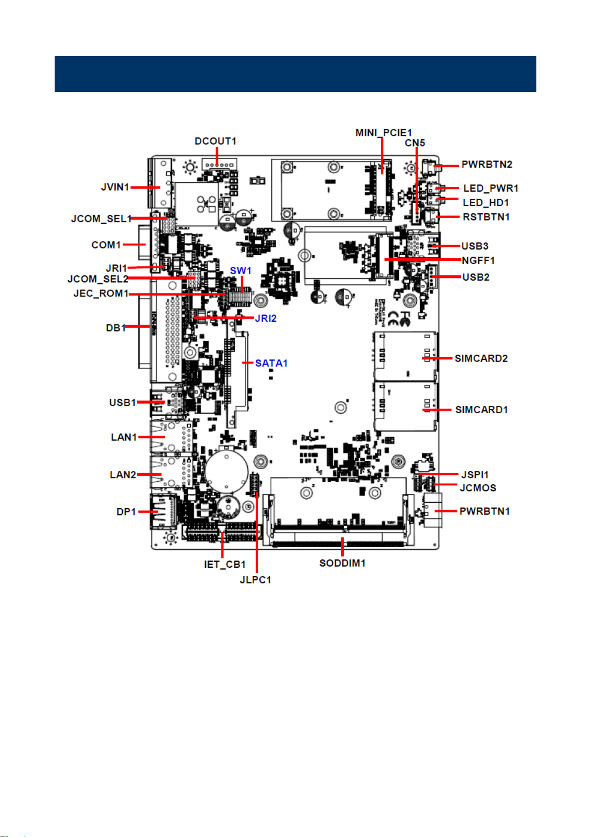
2.2 EBM-SKLUS, AUX-M01, AUX-M02, AUX-M03, AUX-M04, AUX-M07,
EBM-BYTS DB-A and EBM-CDVS DB-A Overviews
2.2.1 EBM-SKLUS
EMS-SKLU/EMS-SKLU-Marine Quick Reference Guide
Page 20
EMS-SKLU/EMS-SKLU-Marine
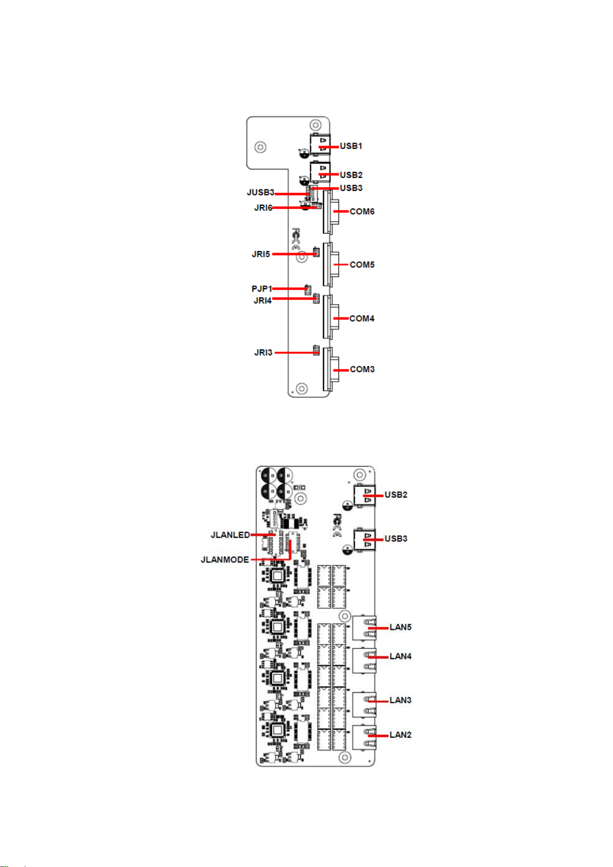
2.2.2 AUX-M01
2.2.3 AUX-M02
20 EMS-SKLU/EMS-SKLU-Marine Quick Reference Guide
Page 21

21
2.2.4 AUX-M03
Quick Reference Guide
EMS-SKLU/EMS-SKLU-Marine Quick Reference Guide
Page 22

EMS-SKLU/EMS-SKLU-Marine
2.2.5 AUX-M04
2.2.6 AUX-M07
22 EMS-SKLU/EMS-SKLU-Marine Quick Reference Guide
Page 23

23
2.2.7 EBM-BYTS DB-A
Quick Reference Guide
2.2.8 EBM-CDVS DB-A
EMS-SKLU/EMS-SKLU-Marine Quick Reference Guide
Page 24
EMS-SKLU/EMS-SKLU-Marine
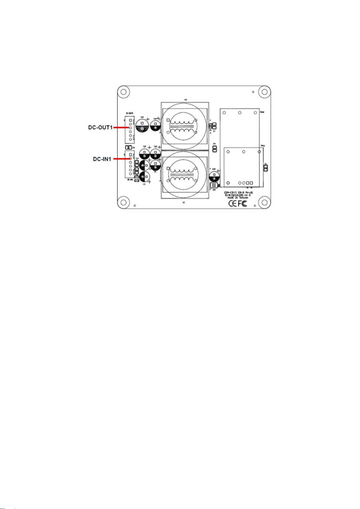
2.2.9 EBM-CDVS DB-B
24 EMS-SKLU/EMS-SKLU-Marine Quick Reference Guide
Page 25

25
Jumpers
Label
Function
Note
JCMOS
Clear CMOS
3 x 2 header, pitch 2.00mm
JRI1/2
COM 1/2 pin 9 signal select
3 x 2 header, pitch 2.00 mm
JCOM_SEL1/2
Serial port 1/2 – RS232/422/485
mode select
4 x 3 header, pitch 2.00 mm
SW1
Multi-function select
DIP switch 8pin
Connectors
Label
Function
Note
USB1
2 x USB3.0 connector
USB2
On-board header for USB2.0
5 x 1 wafer, pitch 2.00 mm
USB3
2 x USB3.0 connector
LAN1/2
RJ-45 Ethernet 1/2
DB-1
Multi-function port
1. COM2
2. Audio(line-in, line-out,
mic-in)
3. 2 x PS/2 for KB/MS
4. 12 bit GPIO/SMBUS
COM1
Serial port connector 1
MINI_PCIE1
Mini PCI Express connector
CN5
Front Panel Connector
5 x 1 wafer, pitch 2.00 mm
PWRBTN1
Power on/off connector
1 x 2 terminal block, pitch 3.50
mm
PWRBTN2
Power on/off button
RSTBTN1
Reset button
LED_PWR1
LED Power
LED_HD1
LED HDD
SIMCARD1/2
SIM card slot 1/2
SODDIM1
DDR4 SODIMM connector
IET_CB1
IET Expansion slot
JLPC1
LPC port connector
5 x 2 header, pitch 2.00 mm
JSPI1
SPI connector
4 x 2 header, pitch 2.00 mm
SATA1
Serial ATA connector
DP1
DP connector
2.3 EBM-SKLUS Jumper & Connector list
Quick Reference Guide
EMS-SKLU/EMS-SKLU-Marine Quick Reference Guide
Page 26

EMS-SKLU/EMS-SKLU-Marine
NGFF1
M.2 KEY-B 2242/3042 connector
DCOUT1
DC Output connector
6 x 1 wafer, pitch 2.50 mm
JVIN1
DC-Input connector
1 x 3 terminal block, pitch 5.08
mm
JEC_ROM1
EC Debug connector
5 x 2 header, pitch 2.00 mm
26 EMS-SKLU/EMS-SKLU-Marine Quick Reference Guide
Page 27
27
In Serial Port 1 mode
RS-232
RS-422
RS-485
1
OFF
ON
ON 2 ON
OFF
ON
In Serial Port 2 mode
RS-232
RS-422
RS-485
3
OFF
ON
ON 4 ON
OFF
ON
Power mode
AT
ATX
5
ON
OFF
DDI1 mode
DisplayPort
HDMI
6
ON
OFF
DDI2 mode
DisplayPort
HDMI
Cable select
7
OFF
OFF
ON
8
ON
OFF
OFF
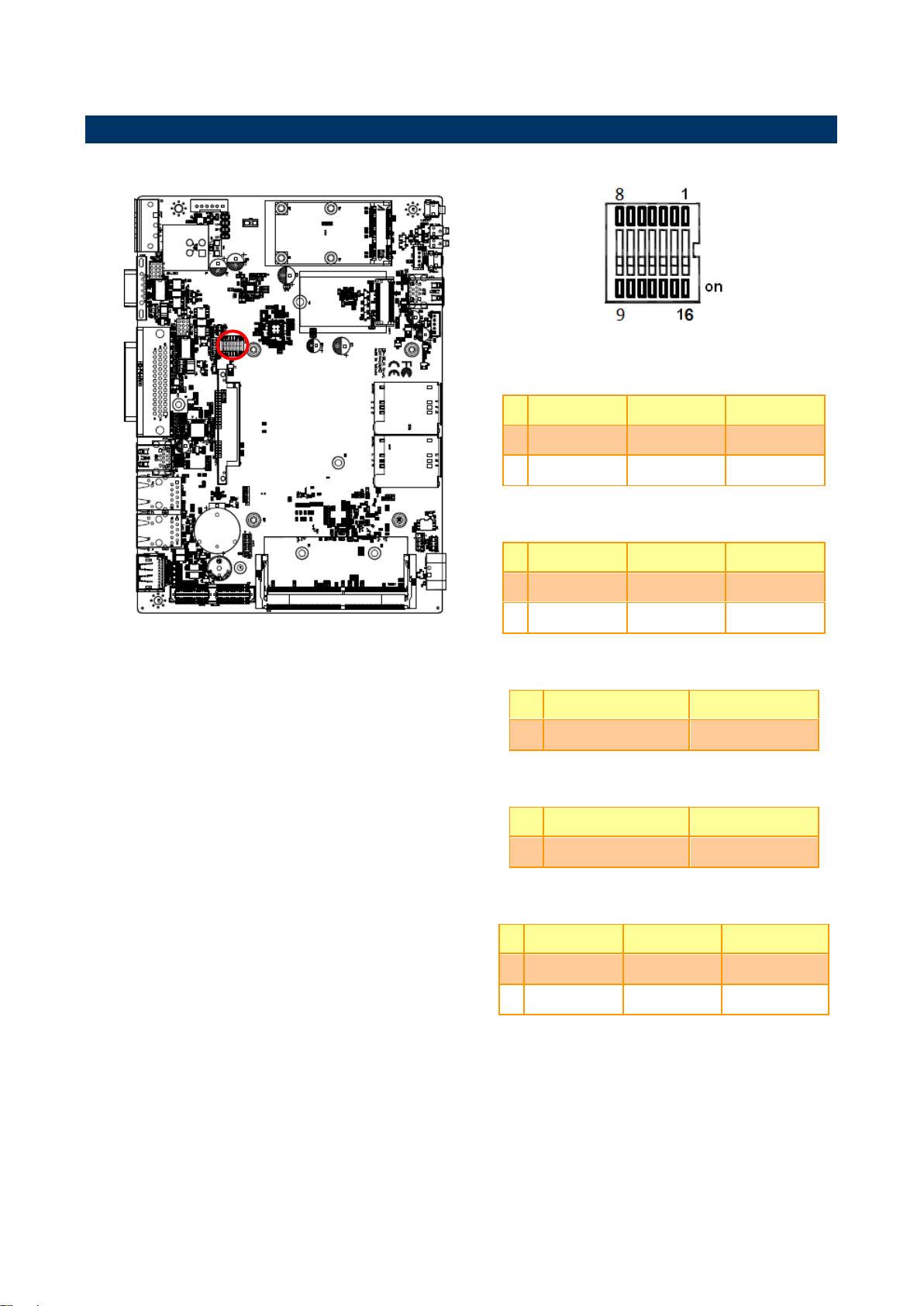
2.4 EBM-SKLUS Jumpers & Connectors settings
2.4.1 Multi-function select (SW1)
Quick Reference Guide
EMS-SKLU/EMS-SKLU-Marine Quick Reference Guide
Page 28

EMS-SKLU/EMS-SKLU-Marine
* Default
Ring*
+5V
+12V
*Default
RS-232*
RS-422/ 485
JRI1
JRI2
JCOM_SEL2
JCOM_SEL1
2.4.2 COM 1/2 pin 9 signal select (JRI1/2)
2.4.3 Serial port 1/2 RS-232/422/485 mode select (JCOM_SEL1/2)
28 EMS-SKLU/EMS-SKLU-Marine Quick Reference Guide
Page 29

29
*Default
Normal*
Clear CMOS
Signal
PIN
PIN
Signal
GND
10 9 LPC_SERIRQ
CLK_24M_PORT80
8 7 LPC_AD3
LPC_LFRAME#
6 5 LPC_AD2
RST_PORT80#
4 3 LPC_AD1
+3.3V
2 1 LPC_AD0
2.4.4 Clear CMOS (JCMOS1)
Quick Reference Guide
2.4.5 LPC port connector (JLPC1)
EMS-SKLU/EMS-SKLU-Marine Quick Reference Guide
Page 30

EMS-SKLU/EMS-SKLU-Marine
Signal
PIN
PIN
Signal
7 HOLD#
SPI_SI
6 5 SPI_SO
SPI_CLK
4 3 SPI0_CS0#
GND
2 1 +3.3VSB
Signal
PIN
PWRBTN_TO_EC#
1
PM_SYSRST#
2
GND
3
+5VSB
4
PWR_LED-
5
2.4.6 SPI connector (JSPI1)
2.4.7 Front Panel Connector (CN5)
30 EMS-SKLU/EMS-SKLU-Marine Quick Reference Guide
Page 31

31
Signal
PIN
+VIN
1
+VIN
2
+VIN
3
GND
4
GND
5
GND
6
Signal
PIN
+DC_IN
1
CHASSIS_GND
2
GND
3
2.4.8 DC Output connector (DCOUT1)
Quick Reference Guide
2.4.9 DC Input connector (JVIN1)
EMS-SKLU/EMS-SKLU-Marine Quick Reference Guide
Page 32

EMS-SKLU/EMS-SKLU-Marine
Signal
PIN
PIN
Signal
EC_SMDAT_DE
BUG
10
9
EC_SMCLK_DE
BUG
NC
8 7 EC_HOLD#
EC_FMOSI
6 5 EC_FMISO
EC_FSCK
4 3 EC_FSCE#
GND
2 1 +VSPI_EC
Signal
PIN
GND
5
GND
4
USB_z_PP2
3
USB_z_PN2
2
+5VSB
1
2.4.10 EC Debug connector (JEC_ROM1)
2.4.11 On-board header for USB2.0 (USB2)
32 EMS-SKLU/EMS-SKLU-Marine Quick Reference Guide
Page 33

33
Signal
PIN
GND
2
PWRBTN#_R
1
2.4.12 Power ON/OFF connector (PWRBTN1)
Quick Reference Guide
EMS-SKLU/EMS-SKLU-Marine Quick Reference Guide
Page 34

EMS-SKLU/EMS-SKLU-Marine
Jumpers
Label
Function
Note
JRI3/4/5/6
COM 3/4/5/6 pin 9 signal select
3 x 2 header, pitch 2.00mm
Connectors
Label
Function
Note
USB1~2
USB connector 1~2
USB3
USB connector 3
5 x 1 wafer, pitch 2.00mm
JUSB3
USB connector 3
5 x 1 header, pitch 2.00mm
COM3~6
Serial port connector 3~6
Connectors
Label
Function
Note
USB2~3
USB connector 2~3
LAN2~5
LAN connector 2~5
JLANLED
LAN ACT/LNK/SPD LED
8 x 2 wafer, pitch 2.00mm
JLANMODE
Normal/Bypass mode LED
6 x 2 wafer, pitch 2.00mm
Connectors
Label
Function
Note
WRSTBTN1
Reset button
WJPRT1
LPT Port
13 x 2 header, pitch 2.00mm
WCN1
System reset
2 x 1 wafer, pitch 2.50mm
WUSB_REAR
USB connector
COM3_7
Serial port connector 3 & 7
COM4_8
Serial port connector 4 & 8
COM5_9
Serial port connector 5 & 9
COM6_10
Serial port connector 6 & 10
WMIOE_IO
IET Expansion slot
2.5 AUX-M01, AUX-M02, AUX-M03, AUX-M04, AUX-M07, EBM-BYTS
DB-A , EBM-CDVS DB-A and EBM-CDVS DB-B Jumper & Connector list
2.5.1 AUX-M01
2.5.2 AUX-M02
2.5.3 AUX-M03
34 EMS-SKLU/EMS-SKLU-Marine Quick Reference Guide
Page 35

35
Jumpers
Label
Function
Note
ZJP1
Operating Modes select
3 x 2 header, pitch 2.00mm
Connectors
Label
Function
Note
ZUSB1~2
USB connector 1~2
LAN2~5
LAN connector 2~5
ZPWR1
Power connector
6 x 1 wafer, pitch 2.00mm
Z_JLANLED
LAN ACT/LNK/SPD LED
8 x 2 wafer, pitch 2.00mm
Connectors
Label
Function
Note
USB1~2
USB connector 1~2
COM3~6
Serial port connector 3~6
Jumpers
Label
Function
Note
OJRI3/4
COM 3/4 pin 9 signal select
3 x 2 header, pitch 2.00mm
Connectors
Label
Function
Note
OUSB1~2
USB connector 1~2
LAN2~3
LAN connector 2~3
COM3~4
Serial port connector 3~4
HDMI1
HDMI connector
3 x 2 header, pitch 2.00mm
OJP485
Serial port 1/ 2 – RS485 mode select
6 x 2 header, pitch 2.00mm
Connectors
Label
Function
Note
USB1~2
USB connector 1~2
2.5.4 AUX-M04
Quick Reference Guide
2.5.5 AUX-M07
2.5.6 EBM-BYTS DB-A
2.5.7 EBM-CDVS DB-A
EMS-SKLU/EMS-SKLU-Marine Quick Reference Guide
Page 36

EMS-SKLU/EMS-SKLU-Marine
PWRBTN
Power button
LED_PWR
LED Power
LED_HDD
LED HDD
CN1
Front Panel connector 1
5 x 1 wafer, pitch 2.00 mm
DVI1
DVI connector
Connectors
Label
Function
Note
DC-IN1
DC Input connector
6 x 1 wafer, pitch 2.50 mm
DC-OUT1
DC Output connector
6 x 1 wafer, pitch 2.50 mm
2.5.8 EBM-CDVS DB-B
36 EMS-SKLU/EMS-SKLU-Marine Quick Reference Guide
Page 37

37
2.6 AUX-M01 Jumpers & Connectors settings
* Default
Ring*
+5V
+12V
Signal
PIN
GND
5
GND
4
PUSBP3
3
PUSBN3
2
PV5A_USB3
1
JRI5
JRI6
JRI4
JRI3
2.6.1 COM 3/4/5/6 pin 9 signal select (JRI3/4/5/6)
Quick Reference Guide
2.6.2 USB connector (USB3)
EMS-SKLU/EMS-SKLU-Marine Quick Reference Guide
Page 38
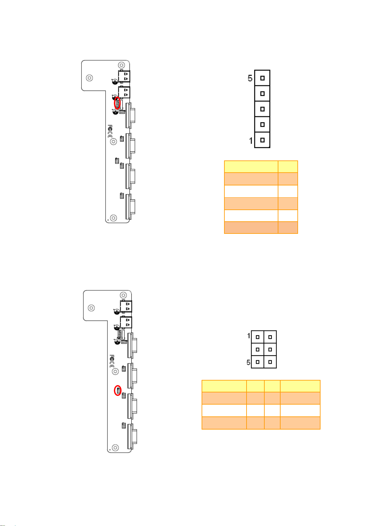
EMS-SKLU/EMS-SKLU-Marine
Signal
PIN
GND
5
GND
4
PUSBP3
3
PUSBN3
2
PV5A_USB3
1
Signal
PIN
PIN
Signal
GND
1 2 MC_9555A0
GND
3 4 MC_9555A1
GND
5 6 MC_9555A2
2.6.3 USB connector (JUSB3)
2.6.4 SMBUS of TCA9555 address setting (PJP1)
38 EMS-SKLU/EMS-SKLU-Marine Quick Reference Guide
Page 39

39
Signal
PIN
PIN
Signal
Z_LAN_LED_1000#_3
15
16
Z_LAN_LED_1000#_1
Z_LAN_LED_100#_3
13
14
Z_LAN_LED_100#_1
Z_LAN_LED_ACT_3
11
12
Z_LAN_LED_ACT_1
+3.3VSB
9
10
+3.3VSB
Z_LAN_LED_1000#_4
7 8 Z_LAN_LED_1000#_2
Z_LAN_LED_100#_4
5 6 Z_LAN_LED_100#_2
Z_LAN_LED_ACT_4
3 4 Z_LAN_LED_ACT_2
+3.3VSB
1 2 +3.3VSB
Signal
PIN
PIN
Signal
Z_RC5_LAN23-STA
11
12
Z_RC7_LAN45-STA
Z_+VLED
9
10
Z_+VLED
Z_RA4_LAN23-BYP
7 8 Z_RA1_LAN45-BYP
Z_+VLED
5 6 Z_+VLED
Z_RC6_LAN23-NOR
3 4 Z_RC4_LAN45-NOR
Z_+VLED
1 2 Z_+VLED
2.7 AUX-M02 Connectors settings
2.7.1 LAN ACT/LNK/SPD LED (JLANLED)
Quick Reference Guide
2.7.2 Normal/Bypass mode LED (JLANMODE)
EMS-SKLU/EMS-SKLU-Marine Quick Reference Guide
Page 40

EMS-SKLU/EMS-SKLU-Marine
Signal
PIN
GND
2
WSYSRST#
1
Signal
PIN
PIN
Signal
GND
26
25
LPT_SLCT
GND
24
23
LPT_[E
GND
22
21
LPT_BUSY
GND
20
19
LPT_ACK#
GND
18
17
PD7
GND
16
15
PD6
GND
14
13
PD5
GND
12
11
PD4
GND
10 9 PD3
LPT_SLIN#
8 7 PD2
LPT_INIT#
6 5 PD1
LPT_ERR#
4 3 PD0
LPT_AFD#
2 1 STB-
2.8 AUX-M03 Connectors settings
2.8.1 System reset (WCN1)
2.8.2 LPT Port (WJPRT1)
40 EMS-SKLU/EMS-SKLU-Marine Quick Reference Guide
Page 41

41
* Default
Auto*
Normal
Reset
Signal
PIN
+V12-28V
1
+V12-28V
2
+V12-28V
3
GND
4
GND
5
GND
6
2.9 AUX-M04 Jumpers & Connectors settings
2.9.1 Operating Modes select (ZJP1)
Quick Reference Guide
2.9.2 Power connector (ZPWR1)
EMS-SKLU/EMS-SKLU-Marine Quick Reference Guide
Page 42

EMS-SKLU/EMS-SKLU-Marine
Signal
PIN
PIN
Signal
Z_LAN_LED_1000#_3
15
16
Z_LAN_LED_1000#_1
Z_LAN_LED_100#_3
13
14
Z_LAN_LED_100#_1
Z_LAN_LED_ACT_3
11
12
Z_LAN_LED_ACT_1
+3.3VSB
9
10
+3.3VSB
Z_LAN_LED_1000#_4
7 8 Z_LAN_LED_1000#_2
Z_LAN_LED_100#_4
5 6 Z_LAN_LED_100#_2
Z_LAN_LED_ACT_4
3 4 Z_LAN_LED_ACT_2
+3.3VSB
1 2 +3.3VSB
2.9.3 LAN ACT/LNK/SPD LED (Z_JLANLED)
42 EMS-SKLU/EMS-SKLU-Marine Quick Reference Guide
Page 43

43
Signal
PIN
PIN
Signal
GND
1 2 SMC_9555A0
GND
3 4 SMC_9555A1
GND
5 6 SMC_9555A2
2.10 AUX-M07 Connector settings
2.10.1 SMBUS of TCA9555 address setting (SJP2)
Quick Reference Guide
EMS-SKLU/EMS-SKLU-Marine Quick Reference Guide
Page 44

EMS-SKLU/EMS-SKLU-Marine
* Default
Ring*
+5V
+12V
In Serial Port 1 mode
PIN
ON
NC
1-2
Auto Direction
RTS# Control*
3-4
485TXP external
biasing resistor
OPEN*
5-6
485TXN external
biasing resistor
OPEN*
In Serial Port 2 mode
ON
NC
7-8
Auto Direction
RTS# Control*
9-10
485TXP external
biasing resistor
OPEN*
11-12
485TXN external
biasing resistor
OPEN*
OJRI4
OJRI3
2.11 EBM-BYTS DB-A Jumpers & Connectors settings
2.11.1 COM 3/4 pin 9 signal select (OJRI3/4)
2.11.2 Serial port 1/ 2 – RS485 mode select (OJP485)
44 EMS-SKLU/EMS-SKLU-Marine Quick Reference Guide
Page 45

45
Signal
PIN
PIN
Signal
GND
1 2 MC_9555A0
GND
3 4 MC_9555A1
GND
5 6 MC_9555A2
2.11.3 SMBUS of TCA9555 address setting (OJP1)
Quick Reference Guide
EMS-SKLU/EMS-SKLU-Marine Quick Reference Guide
Page 46

EMS-SKLU/EMS-SKLU-Marine
Signal
PIN
NC
1
SYSRST#
2
GND
3
SATA_LED#
4
PWRSB_LED-
5
2.12 EBM-CDVS DB-A Connector settings
2.12.1 Front Panel Connector 1 (CN1)
46 EMS-SKLU/EMS-SKLU-Marine Quick Reference Guide
Page 47

47
Signal
PIN
+PWRIN
1
+PWRIN
2
+PWRIN
3
GND
4
GND
5
GND
6
Signal
PIN
+PWROUT
1
+PWROUT
2
+PWROUT
3
GND
4
GND
5
GND
6
2.13 EBM-CDVS DB-B Connector settings
2.13.1 DC Input connector (DC-IN1)
Quick Reference Guide
2.13.2 DC Output connector (DC-OUT1)
EMS-SKLU/EMS-SKLU-Marine Quick Reference Guide
Page 48

EMS-SKLU/EMS-SKLU-Marine
Step 1. Remove 4 screws from the bottom of your system and take it off.
Step 2. Slide the DDR4 SODIMM into the memory socket and press it down until properly seated.
Step 3. Insert MPCIE card into designated locations and fasten with 2 screws to complete MPCIE installation.
Step 4. Insert M.2 B-Key card into designated locations and fasten with a screw to complete installation.
Step 1. Unfasten 2 screws from the HDD bracket and take it off.
Step 2. Remove 4 screws to release the HDD bracket.
Step 3. Slide HDD into its bracket until properly seated.
Step 4. Secure HDD by means of 4 screws.
Step 5. Insert HDD bracket into designated locations and fasten with 2 screws to complete HDD installation.
2.14 Installing Hard Disk & Memory, PCI devices (EMS-SKLU)
48 EMS-SKLU/EMS-SKLU-Marine Quick Reference Guide
Page 49

49
2.15 Installing Mounting Brackets (EMS-SKLU)
Step 1. Position brackets on both sides, matching the holes on the system.
Step 2. Insert and fasten screw on each side of the system to secure Mounting brackets.
Quick Reference Guide
EMS-SKLU/EMS-SKLU-Marine Quick Reference Guide
Page 50

EMS-SKLU/EMS-SKLU-Marine
3.BIOS Setup
50 EMS-SKLU/EMS-SKLU-Marine Quick Reference Guide
Page 51

Quick Reference Guide
51
3.1 Introduction
The BIOS setup program allows users to modify the basic system configuration. In this
following chapter will describe how to access the BIOS setup program and the
configuration options that may be changed.
3.2 Starting Setup
The AMI BIOS™ is immediately activated when you first power on the computer. The BIOS
reads the system information contained in the NVRAM and begins the process of checking
out the system and configuring it. When it finishes, the BIOS will seek an operating system
on one of the disks and then launch and turn control over to the operating system.
While the BIOS is in control, the Setup program can be activated in one of two ways:
By pressing <Del> or <F2> immediately after switching the system on, or
By pressing the <Del> or <F2> key when the following message appears briefly at the
left-top of the screen during the POST (Power On Self Test).
Press <Del> or <F2> to enter SETUP
If the message disappears before you respond and you still wish to enter Setup, restart the
system to try again by turning it OFF then ON or pressing the "RESET" button on the
system case. You may also restart by simultaneously pressing <Ctrl>, <Alt>, and <Delete>
keys. If you do not press the keys at the correct time and the system does not boot, an error
message will be displayed and you will again be asked to.
Press F1 to Continue, DEL to enter SETUP
EMS-SKLU/EMS-SKLU-Marine Quick Reference Guide
Page 52

EMS-SKLU/EMS-SKLU-Marine
Button
Description
↑
Move to previous item
↓
Move to next item
←
Move to the item in the left hand
→
Move to the item in the right hand
Esc key
Main Menu -- Quit and not save changes into NVRAM
Status Page Setup Menu and Option Page Setup Menu -- Exit current page and
return to Main Menu
+ key
Increase the numeric value or make changes
- key
Decrease the numeric value or make changes
F1 key
General help, only for Status Page Setup Menu and Option Page Setup Menu
F2 key
Previous Values.
F3 key
Optimized defaults
F4 key
Save & Exit Setup
3.3 Using Setup
In general, you use the arrow keys to highlight items, press <Enter> to select, use the
PageUp and PageDown keys to change entries, press <F1> for help and press <Esc> to
quit. The following table provides more detail about how to navigate in the Setup program
using the keyboard.
Navigating Through The Menu Bar
Use the left and right arrow keys to choose the menu you want to be in.
Note: Some of the navigation keys differ from one screen to another.
To Display a Sub Menu
Use the arrow keys to move the cursor to the sub menu you want. Then press
<Enter>. A “” pointer marks all sub menus.
52 EMS-SKLU/EMS-SKLU-Marine Quick Reference Guide
Page 53

Quick Reference Guide
53
3.4 Getting Help
Press F1 to pop up a small help window that describes the appropriate keys to use and the
possible selections for the highlighted item. To exit the Help Window press <Esc> or the F1
key again.
3.5 In Case of Problems
If, after making and saving system changes with Setup, you discover that your computer no
longer is able to boot, the AMI BIOS supports an override to the NVRAM settings which
resets your system to its defaults.
The best advice is to only alter settings which you thoroughly understand. To this end, we
strongly recommend that you avoid making any changes to the chipset defaults. These
defaults have been carefully chosen by both BIOS Vendor and your systems manufacturer
to provide the absolute maximum performance and reliability. Even a seemingly small
change to the chipset setup has the potential for causing you to use the override.
EMS-SKLU/EMS-SKLU-Marine Quick Reference Guide
Page 54

EMS-SKLU/EMS-SKLU-Marine
3.6 BIOS setup
Once you enter the Aptio Setup Utility, the Main Menu will appear on the screen. The Main
Menu allows you to select from several setup functions and exit choices. Use the arrow
keys to select among the items and press <Enter> to accept and enter the sub-menu.
3.6.1 Main Menu
This section allows you to record some basic hardware configurations in your computer and
set the system clock.
54 EMS-SKLU/EMS-SKLU-Marine Quick Reference Guide
Page 55

Quick Reference Guide
55
3.6.1.1 System Language
This option allows choosing the system default language.
3.6.1.2 System Date
Use the system date option to set the system date. Manually enter the day, month and
year.
3.6.1.3 System Time
Use the system time option to set the system time. Manually enter the hours, minutes and
seconds.
Note: The BIOS setup screens shown in this chapter are for reference purposes
only, and may not exactly match what you see on your screen.
Visit the Avalue website (www.avalue.com.tw) to download the latest
product and BIOS information.
3.6.2 Advanced Menu
This section allows you to configure your CPU and other system devices for basic operation
through the following sub-menus.
EMS-SKLU/EMS-SKLU-Marine Quick Reference Guide
Page 56

EMS-SKLU/EMS-SKLU-Marine
Item
Options
Description
Security Device Support
Disable,
Enable[Default]
Enables or Disables BIOS support for
security device. O.S. will not show
Security Device. TCG EFI protocol and
INT1A interface will not be available.
SHA-1 PCR Bank
Disabled
Enabled[Default],
Enables or Disables SHA-1 PCR Bank.
SHA256 PCR Bank
Disabled[Default]
Enabled,
Enables or Disables SHA256 PCR
Bank.
Pending operation
None[Default],
TPM Clear
Schedule an Operation for the Security
Device. NOTE: Your Computer will
reboot during restart in order to change
State of Security Device.
Platform Hierarchy
Disabled
Enabled[Default],
Enable or Disable Platform Hierarchy.
Storage Hierarchy
Disabled
Enabled[Default],
Enable or Disable Storage Hierarchy.
Endorsement Hierarchy
Disabled
Enabled[Default],
Enable or Disable Endorsement
Hierarchy.
TPM2.0 UEFI Spec Version
1.0[Default],
1.x
Select the TCG2 Spec Version Support.
1.0: the Compatible mode for
Win8/Win10, 1.x: For TCG2 newer spec
for Win10.
3.6.2.1 Trusted Computing
56 EMS-SKLU/EMS-SKLU-Marine Quick Reference Guide
Page 57

57
Item
Options
Description
Enable Hibernation
Disabled
Enabled[Default],
Enables or Disables System ability to
Hibernate (OS/S4 Sleep State). This
option may be not effective with some
OS.
ACPI Sleep State
Suspend Disabled,
S3 (Suspend to RAM) [Default]
Select the highest ACPI sleep state the
system will enter when the SUSPEND
button is pressed.
ACPI Low Power S0 Idle
Disabled[Default],
Enabled
Enable or Disable ACPI Low Power S0
Idle Support.
ErP Function
Disabled[Default],
Enabled
ErP Function (Deep S5).
PWR-On After PWR-Fail
Off[Default]
On
Last state
AC loss resume.
Watch Dog
Disabled[Default],
30 sec
40 sec
50 sec
1 min
2 min
10 min
30 min
Select WatchDog.
3.6.2.2 ACPI Settings
Quick Reference Guide
EMS-SKLU/EMS-SKLU-Marine Quick Reference Guide
Page 58

EMS-SKLU/EMS-SKLU-Marine
Item
Options
Description
Intel AMT
Disabled
Enabled[Default],
Enable/Disable Intel® Active Management Technology BIOS
Extension. Note: iAMT H/W is always enabled. This option
just controls the BIOS extension execution. If enabled, this
requires additional firmware in the SPI device.
Un-Configure ME
Disabled[Default]
Enabled,
OEMFlag Bit 15: Un-Configure ME without password.
3.6.2.3 AMT Configuration
58 EMS-SKLU/EMS-SKLU-Marine Quick Reference Guide
Page 59
59
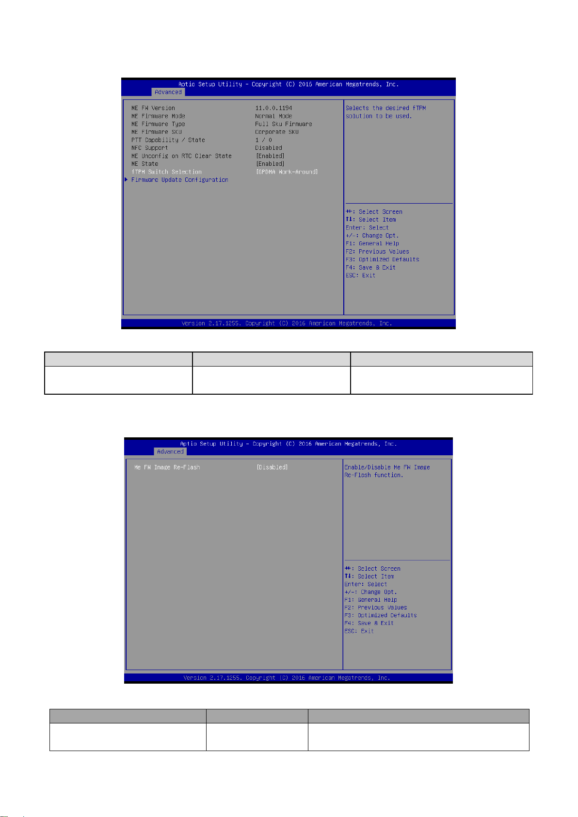
3.6.2.4 PCH-FW Configuration
Item
Options
Description
fTPM Switch Selection
GPDMA Work-Around[Default],
MSFT QFE Solution
Select the desired fTPM solution to be
used.
Item
Option
Description
ME FW Image Re-Flash
Disabled [Default],
Enabled
Enable/Disable Me FW Image Re-Flash function.
Quick Reference Guide
3.6.2.4.1 Firmware Update Configuration
EMS-SKLU/EMS-SKLU-Marine Quick Reference Guide
Page 60

EMS-SKLU/EMS-SKLU-Marine
Item
Description
Serial Port 1 Configuration
Set Parameters of Serial Port 1 (COMA).
Serial Port 2 Configuration
Set Parameters of Serial Port 2 (COMB).
3.6.2.5 IT8528 Super IO Configuration
You can use this item to set up or change the IT8528 Super IO configuration for serial ports.
Please refer to 3.6.2.5.1~ 3.6.2.5.2 for more information.
3.6.2.5.1 Serial Port 1 Configuration
60 EMS-SKLU/EMS-SKLU-Marine Quick Reference Guide
Page 61

61
Item
Option
Description
Serial Port
Enabled[Default],
Disabled
Enable or Disable Serial Port (COM).
Item
Option
Description
Serial Port
Enabled[Default],
Disabled
Enable or Disable Serial Port (COM).
3.6.2.5.2 Serial Port 2 Configuration
Quick Reference Guide
3.6.2.6 EC 8528 H/W Monitor
EMS-SKLU/EMS-SKLU-Marine Quick Reference Guide
Page 62
EMS-SKLU/EMS-SKLU-Marine
Item
Options
Description
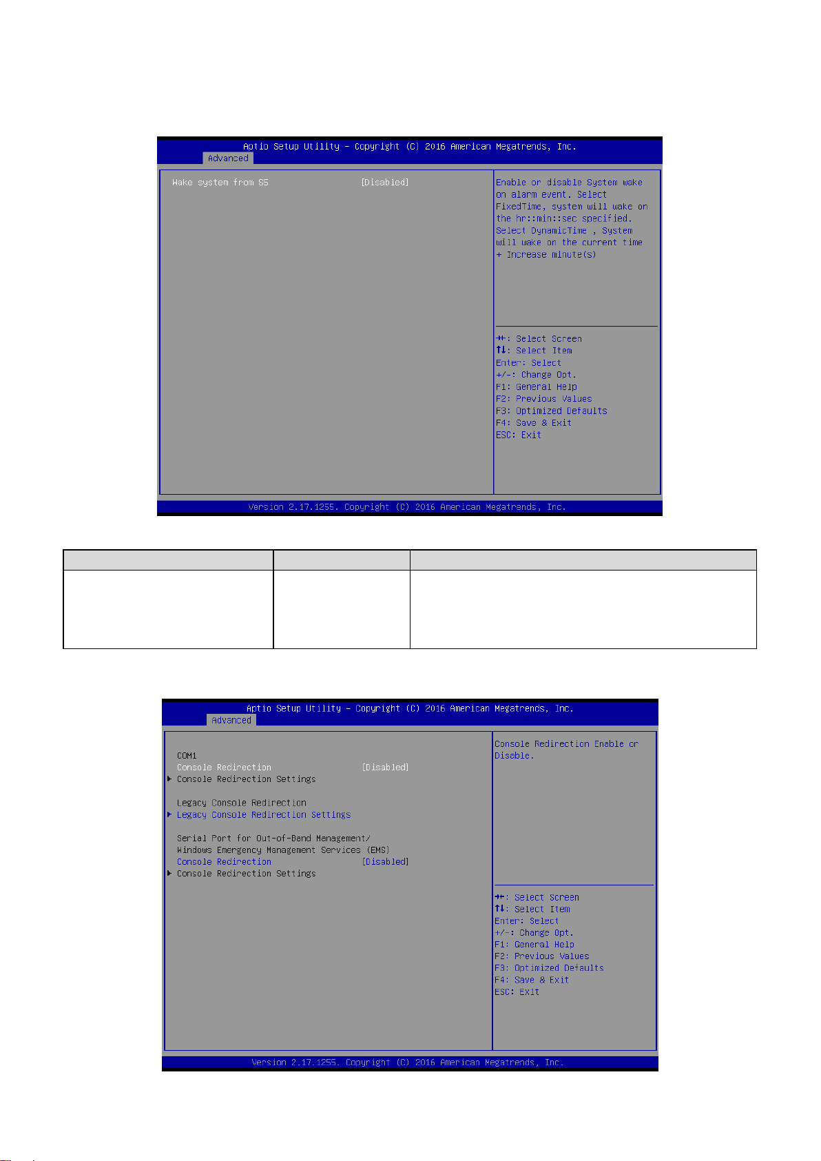
Wake system from S5
Disabled[Default],
Fixed Time
Dynamic Time
Enable or disable System wake on alarm event. Select
Fixed Time, system will wake on the hr::min::sec
specified. Select Dynamic Time, System will wake on
the current time + Increase minute(s).
3.6.2.7 S5 RTC Wake Settings
3.6.2.8 Serial Port Console Redirection
62 EMS-SKLU/EMS-SKLU-Marine Quick Reference Guide
Page 63
63
Item
Options
Description
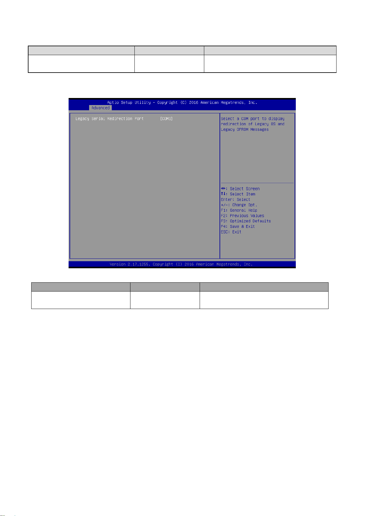
Console Redirection
Disabled[Default],
Enabled
Console Redirection Enable or Disable.
Item
Option
Description
Legacy Serial Redirection Port
COM1[Default],
Select a COM port to display redirection of
Legacy OS and Legacy OPROM Messages.
3.6.2.8.1 Legacy Console Redirection Settings
Quick Reference Guide
EMS-SKLU/EMS-SKLU-Marine Quick Reference Guide
Page 64

EMS-SKLU/EMS-SKLU-Marine
3.6.2.9 CPU Configuration
Use the CPU configuration menu to view detailed CPU specification and configure the
CPU.
3.6.2.10 Intel TXT Information
64 EMS-SKLU/EMS-SKLU-Marine Quick Reference Guide
Page 65
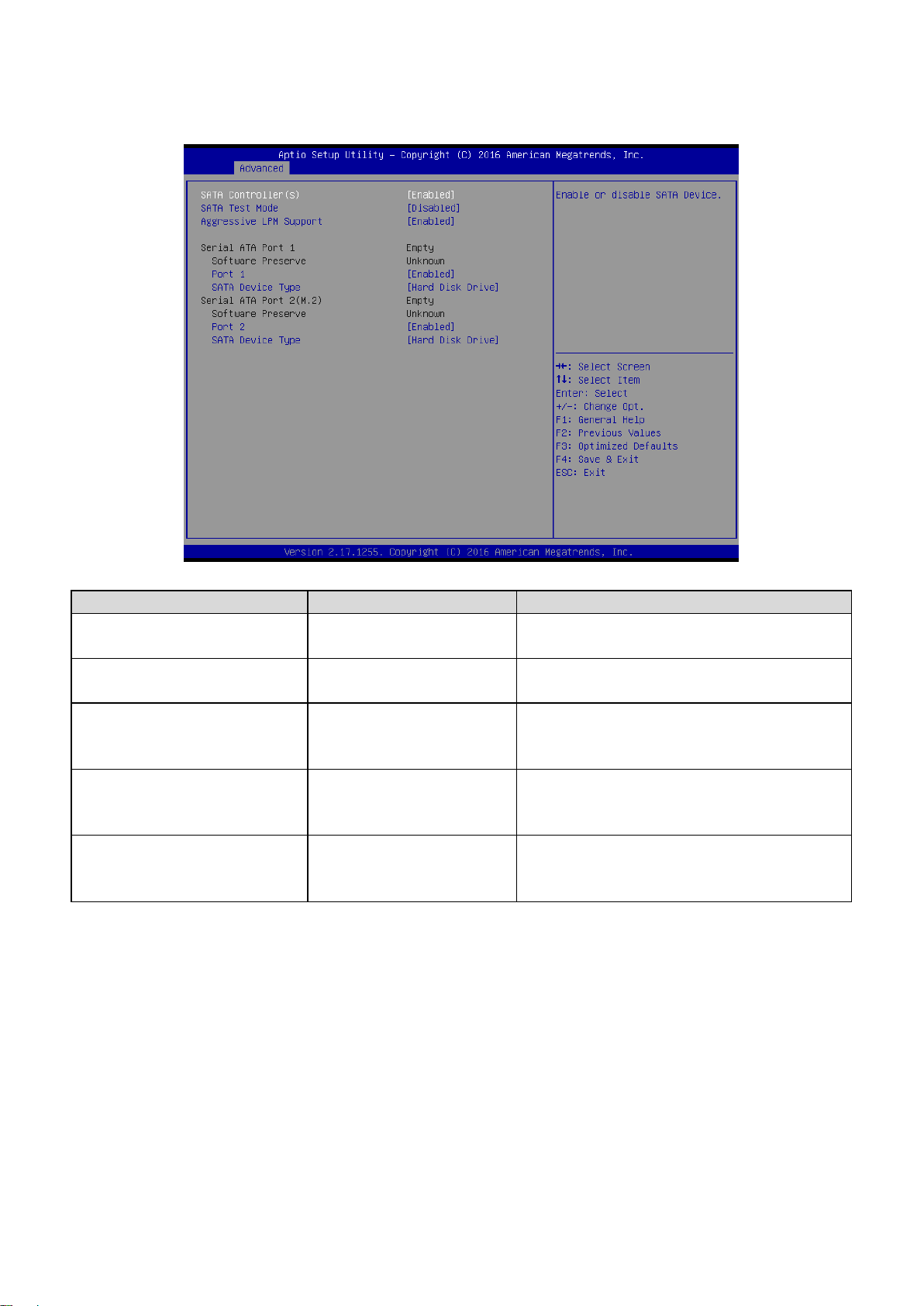
65
Item
Options
Description
SATA Controller(s)
Enabled[Default]
Disabled,
Enable or disable SATA Device.
SATA Test Mode
Enabled
Disabled[Default],
Test Mode Enable/Disable (Loop Back).
Aggressive LPM Support
Enabled[Default]
Disabled
Enable PCH to aggressively enter link power
state.
Port 1/2
Enabled[Default]
Disabled,
Enable or Disable SATA Port.
SATA Device Type
Hard Disk Drive [Default]
Solid State Drive
Identify the SATA port is connected to Solid
State Drive or Hard Disk Drive.
3.6.2.11 SATA Configuration
Quick Reference Guide
EMS-SKLU/EMS-SKLU-Marine Quick Reference Guide
Page 66

EMS-SKLU/EMS-SKLU-Marine
Item
Options
Description
Network Stack
Enabled
Disabled[Default],
Enable/Disable UEFI Network Stack.
Item
Options
Description
CSM Support
Enabled
Disabled[Default]
Enable/Disable CSM Support.
3.6.2.12 Network Stack Configuration
3.6.2.13 CSM Configuration
66 EMS-SKLU/EMS-SKLU-Marine Quick Reference Guide
Page 67

Quick Reference Guide
67
Item
Options
Description
Legacy USB Support
Enabled[Default]
Disabled
Auto
Enables Legacy USB support. AUTO option
disables legacy support if no USB devices are
connected. DISABLE option will keep USB
devices available only for EFI applications.
XHCI Hand-off
Enabled[Default]
Disabled
This is a workaround for OSew without XHCI
hand-off support. The XHCI ownership change
should be claimed by XHCI driver.
USB Mass Storage Driver Support
Enabled[Default]
Disabled
Enable/Disable USB Mass Storage Driver
Support.
Port 60/64 Emulation
Disabled[Default]
Enabled
Enables I/O port 60h/64h emulation support.
This should be enabled for the complete USB
keyboard legacy support for non-USB aware
OSes.
USB transfer time-out
1 sec
5 sec
10 sec
20 sec[Default]
The time-out value for Control, Bulk, and
Interrupt transfers.
Device reset time-out
10 sec
20 sec[Default]
30 sec
40 sec
USB mass storage device Start Unit command
time-out.
Device power-up delay
Auto[Default]
Manual
Maximum time the device will take before it
properly reports itself to the Host Controller.
‘Auto’ uses default value: for a Root port it is
100ms, for a Hub port the delay is taken form
Hub descriptor.
3.6.2.14 USB Configuration
The USB Configuration menu helps read USB information and configures USB settings.
EMS-SKLU/EMS-SKLU-Marine Quick Reference Guide
Page 68
EMS-SKLU/EMS-SKLU-Marine
Hp v220w 1100
Auto[Default]
Floppy
Forced FDD
Hard Disk
CD-ROM
Mass storage device emulation type. ‘AUTO’
enumerates devices according to their media
format. Optical drives are emulated as
‘CDROM’, drives with no media will be
emulated according to d drive type.
Item
Option
Description
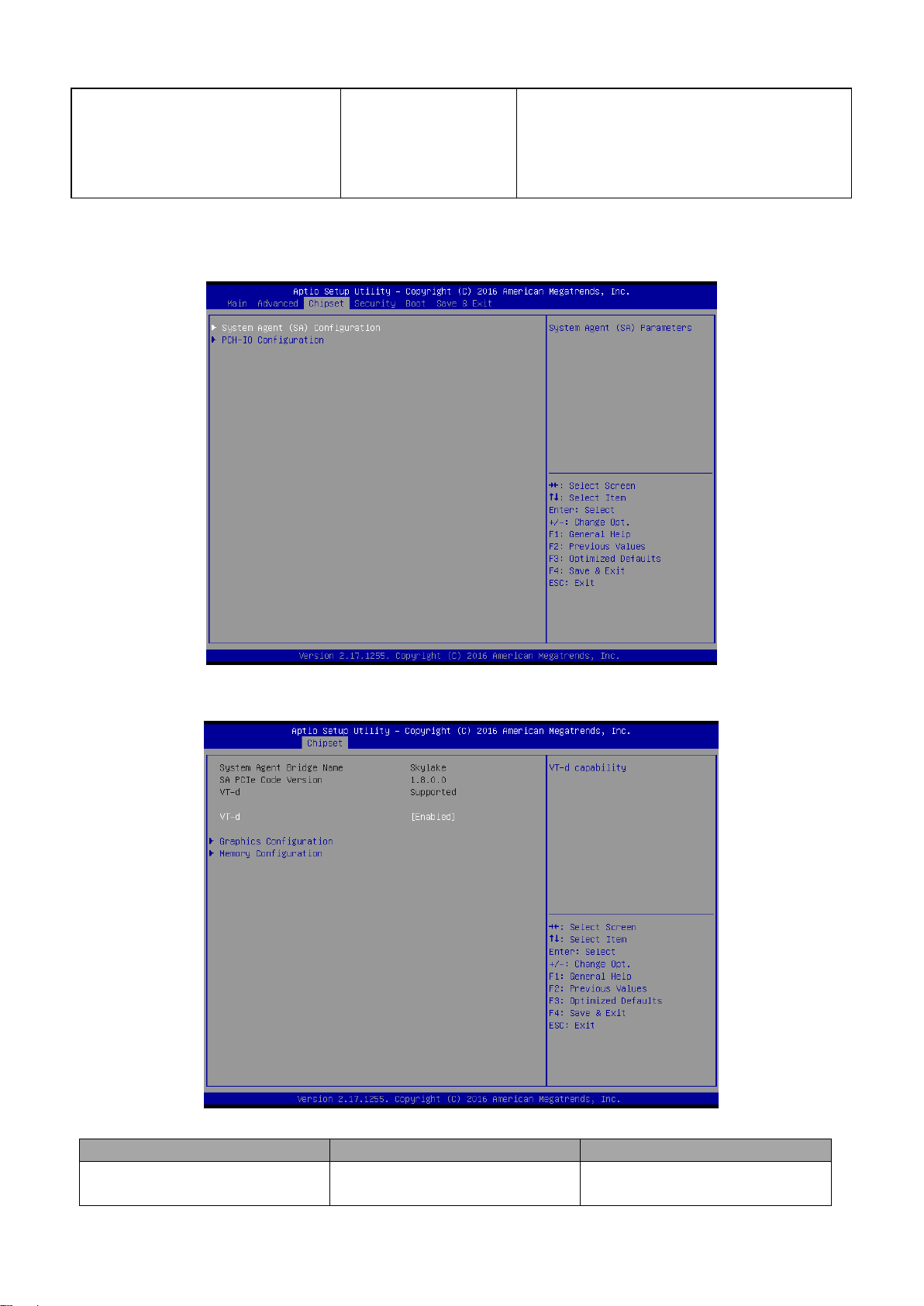
VT-d
Enabled[Default]
Disabled
VT-d capability.
3.6.3 Chipset
3.6.3.1 System Agent (SA) Configuration
68 EMS-SKLU/EMS-SKLU-Marine Quick Reference Guide
Page 69

69
Item
Option
Description
Max TOLUD
Dynamic[Default]
1GB/1.25GB/1.5GB/1.75GB
/2GB/2.25GB/2.5GB/2.75GB
/3GB/3.25GB
Maximum Value of TOLUD. Dynamic
assignment would adjust TOLUD
automatically based on largest MMIO length
of installed graphic controller.
3.6.3.1.1 Graphics Configuration
Quick Reference Guide
3.6.3.1.2 Memory Configuration
EMS-SKLU/EMS-SKLU-Marine Quick Reference Guide
Page 70
EMS-SKLU/EMS-SKLU-Marine
Item
Option
Description
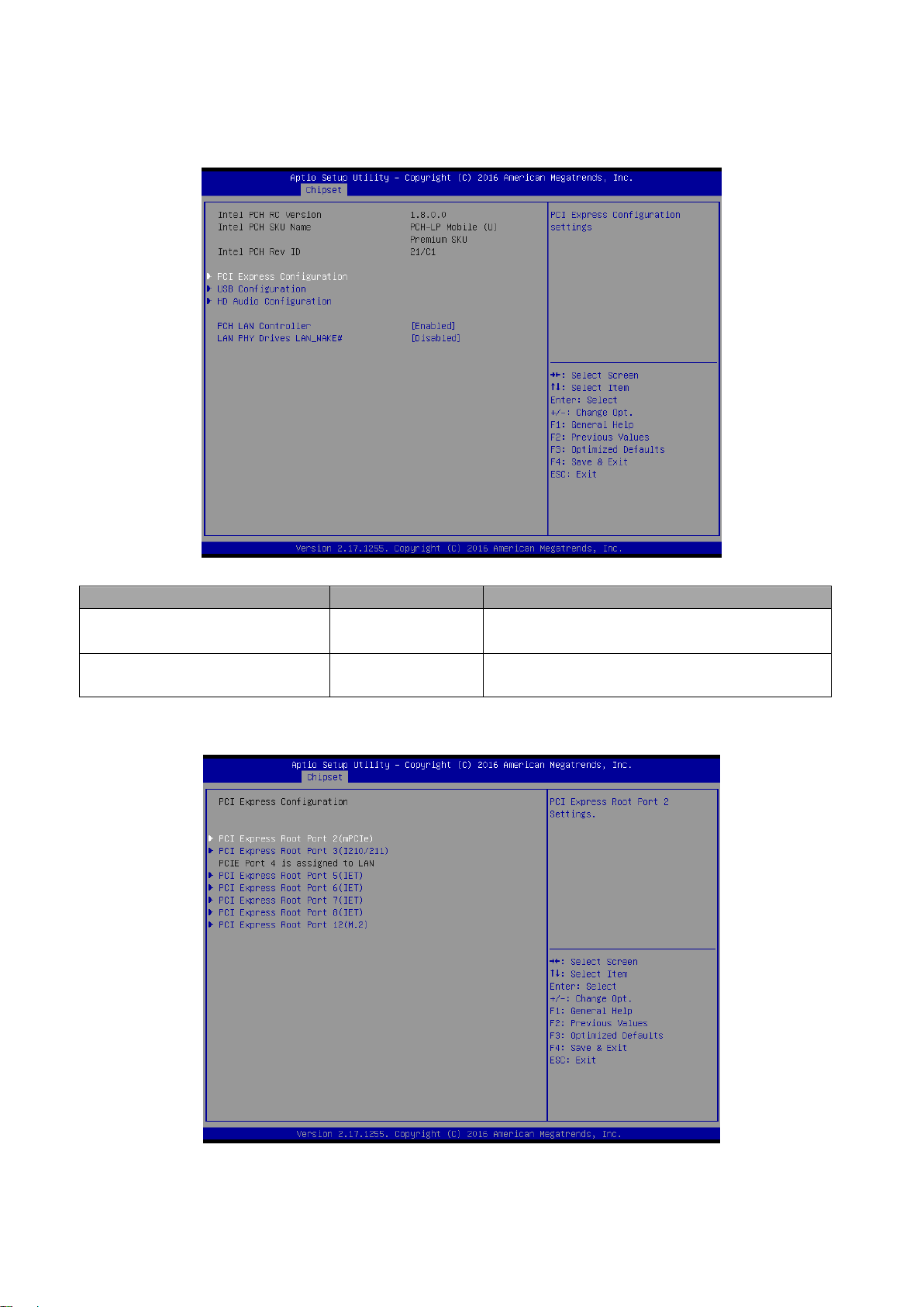
PCH LAN Controller
Disabled
Enabled[Default]
Enable or disable onboard NIC.
LAN PHY Drives LAN_WAKE#
Disabled[Default]
Enabled
Enable/Disable LAN Phy driving LAN_WAKE#
else platform drives LAN_WAKE#.
3.6.3.2 PCH-IO Configuration
3.6.3.2.1 PCI Express Configuration
70 EMS-SKLU/EMS-SKLU-Marine Quick Reference Guide
Page 71

71
Item
Option
Description
PCI Express Root Port 2
Enabled[Default],
Disabled
Control the PCI Express Root Port.
ASPM Support
Disabled [Default],
L0s
L1
L0sL1
Auto
Set the ASPM Level: Force L0s – Force all
links to L0s State AUTO – BIOS auto
configure DISABLE – Disables ASPM.
L1 Substates
Disabled
L1.1
L1.2
L1.1 & L1.2[Default],
PCI Express L1 Substates settings.
PCIe Speed
Auto[Default]
Gen1
Gen2
Gen3
Select PCI Express port speed.
3.6.3.2.1.1 PCI Express Root Port2 (mPCIe)
Quick Reference Guide
EMS-SKLU/EMS-SKLU-Marine Quick Reference Guide
Page 72

EMS-SKLU/EMS-SKLU-Marine
Item
Option
Description
PCI Express Root Port 3
Enabled[Default],
Disabled
Control the PCI Express Root Port.
ASPM Support
Disabled [Default],
L0s
L1
L0sL1
Auto
Set the ASPM Level: Force L0s – Force all
links to L0s State AUTO – BIOS auto
configure DISABLE – Disables ASPM.
L1 Substates
Disabled
L1.1
L1.2
L1.1 & L1.2[Default],
PCI Express L1 Substates settings.
PCIe Speed
Auto[Default]
Gen1
Gen2
Gen3
Select PCI Express port speed.
3.6.3.2.1.2 PCI Express Root Port3 (I210/211)
72 EMS-SKLU/EMS-SKLU-Marine Quick Reference Guide
Page 73

73
Item
Option
Description
PCI Express Root Port 5
Enabled[Default],
Disabled
Control the PCI Express Root Port.
ASPM Support
Disabled [Default],
L0s
L1
L0sL1
Auto
Set the ASPM Level: Force L0s – Force all
links to L0s State AUTO – BIOS auto
configure DISABLE – Disables ASPM.
L1 Substates
Disabled
L1.1
L1.2
L1.1 & L1.2[Default],
PCI Express L1 Substates settings.
PCIe Speed
Auto[Default]
Gen1
Gen2
Gen3
Select PCI Express port speed.
3.6.3.2.1.3 PCI Express Root Port5 (IET)
Quick Reference Guide
EMS-SKLU/EMS-SKLU-Marine Quick Reference Guide
Page 74

EMS-SKLU/EMS-SKLU-Marine
Item
Option
Description
PCI Express Root Port 6
Enabled[Default],
Disabled
Control the PCI Express Root Port.
ASPM Support
Disabled [Default],
L0s
L1
L0sL1
Auto
Set the ASPM Level: Force L0s – Force all
links to L0s State AUTO – BIOS auto
configure DISABLE – Disables ASPM.
L1 Substates
Disabled
L1.1
L1.2
L1.1 & L1.2[Default],
PCI Express L1 Substates settings.
PCIe Speed
Auto[Default]
Gen1
Gen2
Gen3
Select PCI Express port speed.
3.6.3.2.1.4 PCI Express Root Port6 (IET)
74 EMS-SKLU/EMS-SKLU-Marine Quick Reference Guide
Page 75

75
Item
Option
Description
PCI Express Root Port 7
Enabled[Default],
Disabled
Control the PCI Express Root Port.
ASPM Support
Disabled [Default],
L0s
L1
L0sL1
Auto
Set the ASPM Level: Force L0s – Force all
links to L0s State AUTO – BIOS auto
configure DISABLE – Disables ASPM.
L1 Substates
Disabled
L1.1
L1.2
L1.1 & L1.2[Default],
PCI Express L1 Substates settings.
PCIe Speed
Auto[Default]
Gen1
Gen2
Gen3
Select PCI Express port speed.
3.6.3.2.1.5 PCI Express Root Port7 (IET)
Quick Reference Guide
EMS-SKLU/EMS-SKLU-Marine Quick Reference Guide
Page 76

EMS-SKLU/EMS-SKLU-Marine
Item
Option
Description
PCI Express Root Port 8
Enabled[Default],
Disabled
Control the PCI Express Root Port.
ASPM Support
Disabled [Default],
L0s
L1
L0sL1
Auto
Set the ASPM Level: Force L0s – Force all
links to L0s State AUTO – BIOS auto
configure DISABLE – Disables ASPM.
L1 Substates
Disabled
L1.1
L1.2
L1.1 & L1.2[Default],
PCI Express L1 Substates settings.
PCIe Speed
Auto[Default]
Gen1
Gen2
Gen3
Select PCI Express port speed.
3.6.3.2.1.6 PCI Express Root Port8 (IET)
76 EMS-SKLU/EMS-SKLU-Marine Quick Reference Guide
Page 77

77
Item
Option
Description
PCI Express Root Port 12
Enabled[Default],
Disabled
Control the PCI Express Root Port.
ASPM Support
Disabled [Default],
L0s
L1
L0sL1
Auto
Set the ASPM Level: Force L0s – Force all
links to L0s State AUTO – BIOS auto
configure DISABLE – Disables ASPM.
L1 Substates
Disabled
L1.1
L1.2
L1.1 & L1.2[Default],
PCI Express L1 Substates settings.
PCIe Speed
Auto[Default]
Gen1
Gen2
Gen3
Select PCI Express port speed.
3.6.3.2.1.7 PCI Express Root Port12 (M.2)
Quick Reference Guide
EMS-SKLU/EMS-SKLU-Marine Quick Reference Guide
Page 78

EMS-SKLU/EMS-SKLU-Marine
Item
Option
Description
USB Precondition
Enabled
Disabled[Default],
Precondition work on USB host controller
and root ports for faster enumeration.
XHCI Disable Compliance Mode
FALSE[Default],
TRUE
Option to disable Compliance Mode. Default
is FALSE to not disable Compliance Mode.
Set TRUE to disable Compliance Mode.
USB SS Physical Connector #2(M.2)
Disabled[Default]
Enabled
Enable/Disable USB port.
3.6.3.2.2 USB Configuration
78 EMS-SKLU/EMS-SKLU-Marine Quick Reference Guide
Page 79

79
Item
Option
Description
HD Audio
Disabled
Enabled
Auto[Default],
Control Detection of the HD-Audio device. Disable = HDA will
be unconditionally disabled Enabled = HDA will be
unconditionally enabled Auto = HDA will be enabled if
present, disabled otherwise.
3.6.3.2.3 HD Audio Configuration
Quick Reference Guide
3.6.4 Security
EMS-SKLU/EMS-SKLU-Marine Quick Reference Guide
Page 80

EMS-SKLU/EMS-SKLU-Marine
Item
Option
Description
Secure Boot
Disabled[Default]
Enabled
Secure Boot can be enabled if 1.System running
in User mode with enrolled Platform Key(PK)
2.CSM function is disabled.
Secure Boot Mode
Standard
Custom[Default]
Secure Boot mode selector. ‘Custom’ Mode
enables users to change Image Execution policy
and manage Secure Boot Keys.
Administrator Password
Set setup Administrator Password
User Password
Set User Password
3.6.4.1 Secure Boot menu
80 EMS-SKLU/EMS-SKLU-Marine Quick Reference Guide
Page 81

81
Item
Option
Description
Provision Factory Default keys
Enabled,
Disabled[Default]
Install factory default Secure Boot Keys
when System is in Setup Mode.
3.6.4.1.1 Key Management
Quick Reference Guide
EMS-SKLU/EMS-SKLU-Marine Quick Reference Guide
Page 82
EMS-SKLU/EMS-SKLU-Marine
Item
Option
Description
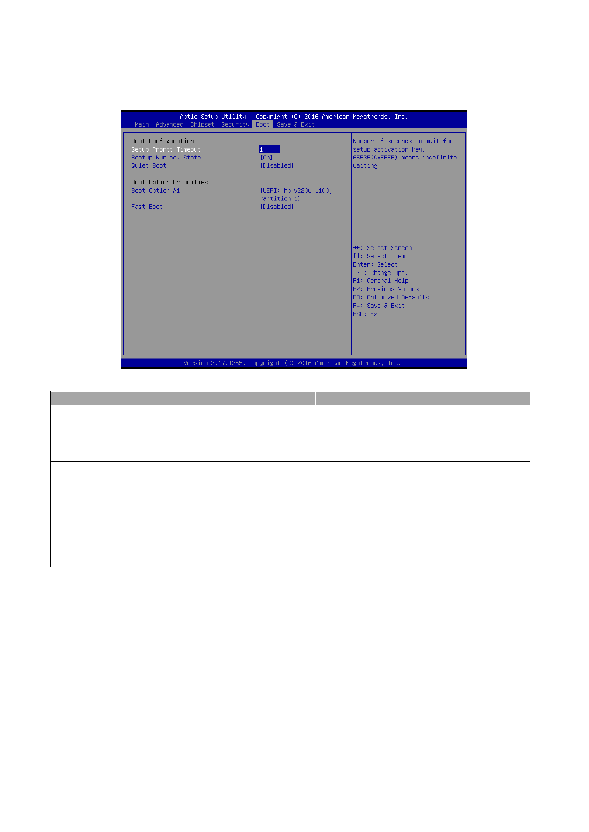
Setup Prompt Timeout
1~ 65535
Number of seconds to wait for setup activation
key. 65535(0xFFFF) means indefinite waiting.
Bootup NumLock State
On[Default]
Off
Select the Keyboard NumLock state
Quiet Boot
Disabled[Default]
Enabled
Enables or disables Quiet Boot option
Fast Boot
Disabled[Default]
Enabled
Enables or disables boot with initialization of a
minimal set of devices required to launch
active boot option. Has no effect for BBS boot
options.
Boot Option #1/2
Set the system boot order.
3.6.5 Boot
82 EMS-SKLU/EMS-SKLU-Marine Quick Reference Guide
Page 83

83
3.6.6 Save and exit
Quick Reference Guide
3.6.6.1 Save Changes and Reset
Reset the system after saving the changes.
EMS-SKLU/EMS-SKLU-Marine Quick Reference Guide
Page 84

EMS-SKLU/EMS-SKLU-Marine
3.6.6.2 Discard Changes and Reset
Any changes made to BIOS settings during this session of the BIOS setup program are
discarded. The setup program then exits and reboots the controller.
3.6.6.3 Restore Defaults
This option restores all BIOS settings to the factory default. This option is useful if the
controller exhibits unpredictable behavior due to an incorrect or inappropriate BIOS setting.
3.6.6.4 Launch EFI Shell from filesystem device
Attempts to Launch EFI Shell application (Shellx64.efi) from one of the available filesystem
devices.
84 EMS-SKLU/EMS-SKLU-Marine Quick Reference Guide
Page 85

Quick Reference Guide
85
4. Drivers Installation
Note: Installation procedures and screen shots in this section are
for your reference and may not be exactly the same as
shown on your screen.
EMS-SKLU/EMS-SKLU-Marine Quick Reference Guide
Page 86

EMS-SKLU/EMS-SKLU-Marine
Insert the Supporting DVD-ROM to
DVD-ROM drive, and it should show the
index page of Avalue’s products
automatically. If not, locate Index.htm and
choose the product from the menu left, or
link to \Driver_Chipset\Intel\EMS-SKLU.
Note: The installation procedures and
screen shots in this section are
based on Windows 10 operation
system. If the warning message
appears while the installation
process, click Continue to go on.
Step 3. Click Install.
Step1. Click Next.
Step 4. Click Restart Now/Restart Later to
complete setup.
Step 2. Click Accept.
4.1 Install Chipset Driver
86 EMS-SKLU/EMS-SKLU-Marine Quick Reference Guide
Page 87
87
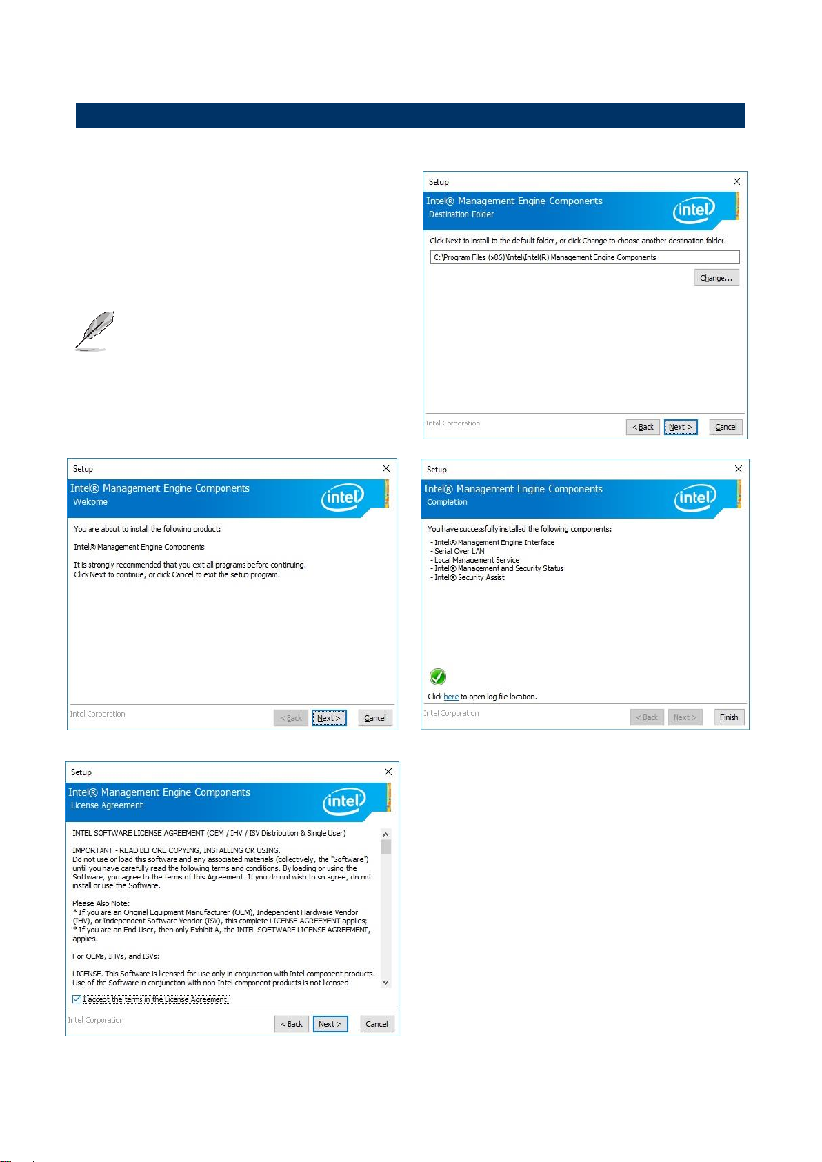
4.2 Install ME Driver
Insert the Supporting DVD-ROM to
DVD-ROM drive, and it should show the
index page of Avalue’s products
automatically. If not, locate Index.htm and
choose the product from the menu left, or
link to \Utility\EMS-SKLU_ME.
Note: The installation procedures and
screen shots in this section are based
on Windows 10 operation system. If
the warning message appears while
the installation process, click
Continue to go on.
Step 3. Click Next to proceed setup.
Step1. Click Next to start installation.
Step 4. Click Finish to complete setup.
Step 2. Click Next.
Quick Reference Guide
EMS-SKLU/EMS-SKLU-Marine Quick Reference Guide
Page 88
EMS-SKLU/EMS-SKLU-Marine
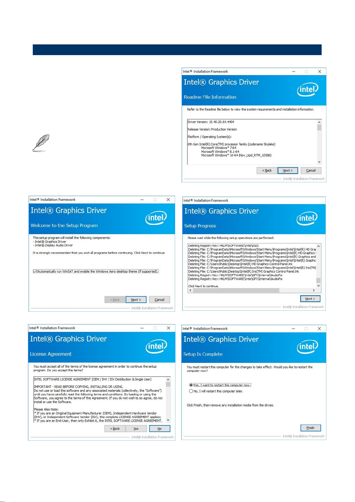
Insert the Supporting DVD-ROM to
DVD-ROM drive, and it should show the
index page of Avalue’s products
automatically. If not, locate Index.htm and
choose the product from the menu left, or link
to \VGA\EMS-SKLU.
Note: The installation procedures and
screen shots in this section are based
on Windows 10 operation system.
Step 3. Click Next.
Step 1. Click Next to continue installation.
Step 4. Click Next.
Step 2.
Click Yes to accept license agreement.
Step 5. Click Finish to complete setup.
4.3 Install VGA Driver
88 EMS-SKLU/EMS-SKLU-Marine Quick Reference Guide
Page 89

89
4.4 Install Audio Driver (For Realtek ALC892)
Insert the Supporting CD-ROM to CD-ROM drive,
and it should show the index page of Avalue’s
products automatically. If not, locate Index.htm and
choose the product from the menu left, or link to
\Driver_Audio\Realtek\ALC892\EMS-SKLU_Audio.
Note: The installation procedures and screen shots in
this section are based on Windows 10 operation
system.
Step 1. Click Next to continue setup.
Step 2. Click Finish to complete the setup.
Quick Reference Guide
EMS-SKLU/EMS-SKLU-Marine Quick Reference Guide
Page 90

EMS-SKLU/EMS-SKLU-Marine
Insert the Supporting DVD-ROM to DVD-ROM
drive, and it should show the index page of
Avalue’s products automatically. If not, locate
Index.htm and choose the product from the
menu left, or link to
\Driver_Gigabit\Intel\I219LM\EMS-SKLU_LAN.
Note: The installation procedures and screen
shots in this section are based on
Windows 10 operation system.
Step 3. Click Next.
Step 1. Click Install Drivers and Software.
Step 4. Click Next.
Step 2. Click Next.
Step 5. Click Install.
4.5 Install Ethernet Driver
90 EMS-SKLU/EMS-SKLU-Marine Quick Reference Guide
Page 91

Quick Reference Guide
91 Step 6. Click Finish to complete the setup.
EMS-SKLU/EMS-SKLU-Marine Quick Reference Guide
 Loading...