

Page 1

EEV-Q701
3.5 inch Qseven Carrier Board
Quick Installation Guide
1st Ed – 02 March 2012
Part No. E2017221000R
Page 2

EEV-Q701
FCC Statement
Copyright Notice
Trademark Acknowledgement
Disclaimer
THIS DEVICE COMPLIES WITH PART 15 FCC RULES. OPERATION IS
SUBJECT TO THE FOLLOWING TWO CONDITIONS:
(1) THIS DEVICE MAY NOT CAUSE HARMFUL INTERFERENCE.
(2) THIS DEVICE MUST ACCEPT ANY INTERFERENCE RECEIVED INCLUDING
INTERFERENCE THAT MAY CAUSE UNDESIRED OPERATION.
THIS EQUIPMENT HAS BEEN TESTED AND FOUND TO COMPLY WITH THE LIMITS
FOR A CLASS "A" DIGITAL DEVICE, PURSUANT TO PART 15 OF THE FCC RULES.
THESE LIMITS ARE DESIGNED TO PROVIDE REASONABLE PROTECTION AGAINST
HARMFUL INTERFERENCE WHEN THE EQUIPMENT IS OPERATED IN A
COMMERCIAL ENVIRONMENT. THIS EQUIPMENT GENERATES, USES, AND CAN
RADIATE RADIO FREQUENCY ENERGY AND, IF NOT INSTALLED AND USED IN
ACCORDANCE WITH THE INSTRUCTION MANUAL, MAY CAUSE HARMFUL
INTERFERENCE TO RADIO COMMUNICATIONS.
OPERATION OF THIS EQUIPMENT IN A RESIDENTIAL AREA IS LIKELY TO CAUSE
HARMFUL INTERFERENCE IN WHICH CASE THE USER WILL BE REQUIRED TO
CORRECT THE INTERFERENCE AT HIS OWN EXPENSE.
Copyright 2012 Avalue Technology Inc., ALL RIGHTS RESERVED.
No part of this document may be reproduced, copied, translated, or transmitted in any form
or by any means, electronic or mechanical, for any purpose, without the prior written
permission of the original manufacturer.
Brand and product names are trademarks or registered trademarks of their respective
owners.
Avalue Technology Inc. reserves the right to make changes, without notice, to any product,
including circuits and/or software described or contained in this manual in order to improve
design and/or performance. Avalue Technology assumes no responsibility or liability for the
use of the described product(s), conveys no license or title under any patent, copyright, or
masks work rights to these products, and makes no representations or warranties that
these products are free from patent, copyright, or mask work right infringement, unless
otherwise specified. Applications that are described in this manual are for illustration
purposes only. Avalue Technology Inc. makes no representation or warranty that such
application will be suitable for the specified use without further testing or modification.
2 EEV-Q701 Quick Installation Guide
Page 3

Quick Installation Guide
Life Support Policy
A Message to the Customer
Avalue Technology’s PRODUCTS ARE NOT FOR USE AS CRITICAL COMPONENTS IN
LIFE SUPPORT DEVICES OR SYSTEMS WITHOUT THE PRIOR WRITTEN APPROVAL
OF Avalue Technology Inc.
As used herein:
1. Life support devices or systems are devices or systems which, (a) are intended for
surgical implant into body, or (b) support or sustain life and whose failure to perform,
when properly used in accordance with instructions for use provided in the labeling, can
be reasonably expected to result in significant injury to the user.
2 A critical component is any component of a life support device or system whose failure
to perform can be reasonably expected to cause the failure of the life support device or
system, or to affect its safety or effectiveness.
Avalue Customer Services
Each and every Avalue’s product is built to the most exacting specifications to ensure
reliable performance in the harsh and demanding conditions typical of industrial
environments. Whether your new Avalue device is destined for the laboratory or the factory
floor, you can be assured that your product will provide the reliability and ease of operation
for which the name Avalue has come to be known.
Your satisfaction is our primary concern. Here is a guide to Avalue’s customer services. To
ensure you get the full benefit of our services, please follow the instructions below carefully.
Technical Support
We want you to get the maximum performance from your products. So if you run into
technical difficulties, we are here to help. For the most frequently asked questions, you can
easily find answers in your product documentation. These answers are normally a lot more
detailed than the ones we can give over the phone. So please consult the user’s manual
first.
To receive the latest version of the user’s manual; please visit our Web site at:
http://www.avalue.com.tw/
If you still cannot find the answer, gather all the information or questions that apply to your
problem, and with the product close at hand, call your dealer. Our dealers are well trained
and ready to give you the support you need to get the most from your Avalue’s products. In
fact, most problems reported are minor and are able to be easily solved over the phone.
EEV-Q701 Quick Installation Guide 3
Page 4

EEV-Q701
Headquarters and Branch
Avalue USA
Avalue Technology Inc.
7F, 228, Lian-cheng Road, Chung Ho City, Taipei,
Taiwan
Tel:+886-2-8226-2345
Fax: +886-2-8226-2777
Information:sales@avalue.com.tw
Service: service@avalue.com.tw
Avalue Technology Inc.
9 Timber Lane, Marlboro, NJ 07746-1443
Tel: (732) 414-6500
Fax: (732) 414-6501
Information: sales@avalue-usa.com
Service: support@avalue-usa.com
BCM Advanced Research
Avalue Europe
BCM Advanced Research
an Avalue Company
7 Marconi, Irvine, CA92618
Tel: +1-949-470-1888
Fax: +1-949-470-0971
Information: BCMSales@bcmcom.com
Web: www.bcmcom.com
Avalue Europe A/S
Moelledalen 22C, 3140
Aalsgaarde, Denmark
Tel: +45-7025-0310
Fax:+45-4975-5026
Information: sales.europe@avalue.com.tw
Service: service.europe@avalue.com.tw
Avalue China
Avalue Japan
Avalue Technology Inc.
Room 805, Building 9,No.99 Tianzhou Rd.,
Caohejing Development Area,
Xuhui District, Shanghai
Tel: +86-21-5169-3609
Fax:+86-21-5445-3266
Information: sales.china@avalue.com.cn
Service: service@avalue.com.tw
Avalue Technology Inc.
2F keduka-Bldg, 2-27-3 Taito,
Taito-Ku, Tokyo 110-0016 Japan
Tel: +81-3-5807-2321
Fax: +81-3-5807-2322
Information: sales.japan@avalue.com.tw
Service: service@avalue.com.tw
In addition, free technical support is available from Avalue’s engineers every business day.
We are always ready to give advice on application requirements or specific information on
the installation and operation of any of our products. Please do not hesitate to call or e-mail
us.
4 EEV-Q701 Quick Installation Guide
Page 5

Quick Installation Guide
Contents
1. Getting Started ........................................................................................................... 6
1.1 Safety Precautions ................................................................................................ 6
1.2 Packing List ........................................................................................................... 6
2. Hardware Configuration ............................................................................................ 7
2.1 Product Overview .................................................................................................. 8
2.2 Jumper and Connector List.................................................................................. 10
2.3 Setting Jumpers & Connectors ............................................................................ 12
2.3.1 Touch selector (JTOUCH1) ..................................................................................................... 12
2.3.2 Brightness adjuster (JVR1)...................................................................................................... 12
2.3.3 Touch connector (JTOUCH2) .................................................................................................. 13
2.3.4 USB power selector (JUSB_PW1) .......................................................................................... 13
2.3.5 Clear COMS (JCMOS1) .......................................................................................................... 14
2.3.6 AT/ATX & Miscellaneous setting connector (JFPT1) .............................................................. 15
2.3.7 Module/Carrier BIOS selector (JBIOS1) .................................................................................. 16
2.3.8 SATA power connector (JSPWR1) ......................................................................................... 16
2.3.9 COM1 Dsub_ 9 signal selector (JRI1) ..................................................................................... 17
2.3.10 COM2 in RS422/485 signal selector (JRI2) ............................................................................ 18
2.3.11 Serial port 2 in RS-422/485 mode (JCOM2) ........................................................................... 19
2.3.12 CPU fan connector (JCPU_FAN1) .......................................................................................... 19
2.3.13 Battery connector (JBT1) ......................................................................................................... 20
2.3.14 System Fan connector (FAN1) ................................................................................................ 20
2.3.15 Audio connector (JAUD1) ........................................................................................................ 21
2.3.16 LCD Inverter Connector (JBKL1) ............................................................................................ 21
2.3.16.1 Signal Description – LCD Inverter Connector (JBKL1) ................ 22
2.3.17 CD-ROM Audio Connector (JCD1) ......................................................................................... 22
2.3.18 General Purpose I/O Connector (JDIO1) ................................................................................ 23
2.3.19 IrDA Connector (JIR1) ............................................................................................................. 23
2.3.20 PS/2 keyboard & mouse connector (JKB1) ............................................................................. 24
2.3.21 LPC Connector (JLPC1) .......................................................................................................... 24
2.3.22 LVDS connector (JLVDS1) ...................................................................................................... 25
2.3.23 SPI connector (JSPI1) ............................................................................................................. 26
2.3.24 USB Connector 4 & 5 (JUSB3) ............................................................................................... 26
2.3.25 Qseven connector (JQSEVEN1) ............................................................................................. 27
EEV-Q701 Quick Installation Guide 5
Page 6
EEV-Q701
1. Getting Started
1.1 Safety Precautions
Warning!
Always completely disconnect the power cord from your
chassis whenever you work with the hardware. Do not
make connections while the power is on. Sensitive
electronic components can be damaged by sudden power
surges. Only experienced electronics personnel should
open the PC chassis.
Caution!
Always ground yourself to remove any static charge before
touching the CPU card. Modern electronic devices are very
sensitive to static electric charges. As a safety precaution,
use a grounding wrist strap at all times. Place all electronic
components in a static-dissipative surface or static-shielded
bag when they are not in the chassis.
1.2 Packing List
Before you begin installing your single board, please make sure that the
following materials have been shipped:
1 x 3.5 inch Qseven Carrier Board
1 x Quick Installation Guide
1 x DVD-ROM containing the followings:
— User’s Manual (this manual in PDF file)
— Audio drivers and utilities
6 EEV-Q701 Quick Installation Guide
Page 7

Quick Installation Guide
2. Hardware
Configuration
EEV-Q701 Quick Installation Guide 7
Page 8
EEV-Q701
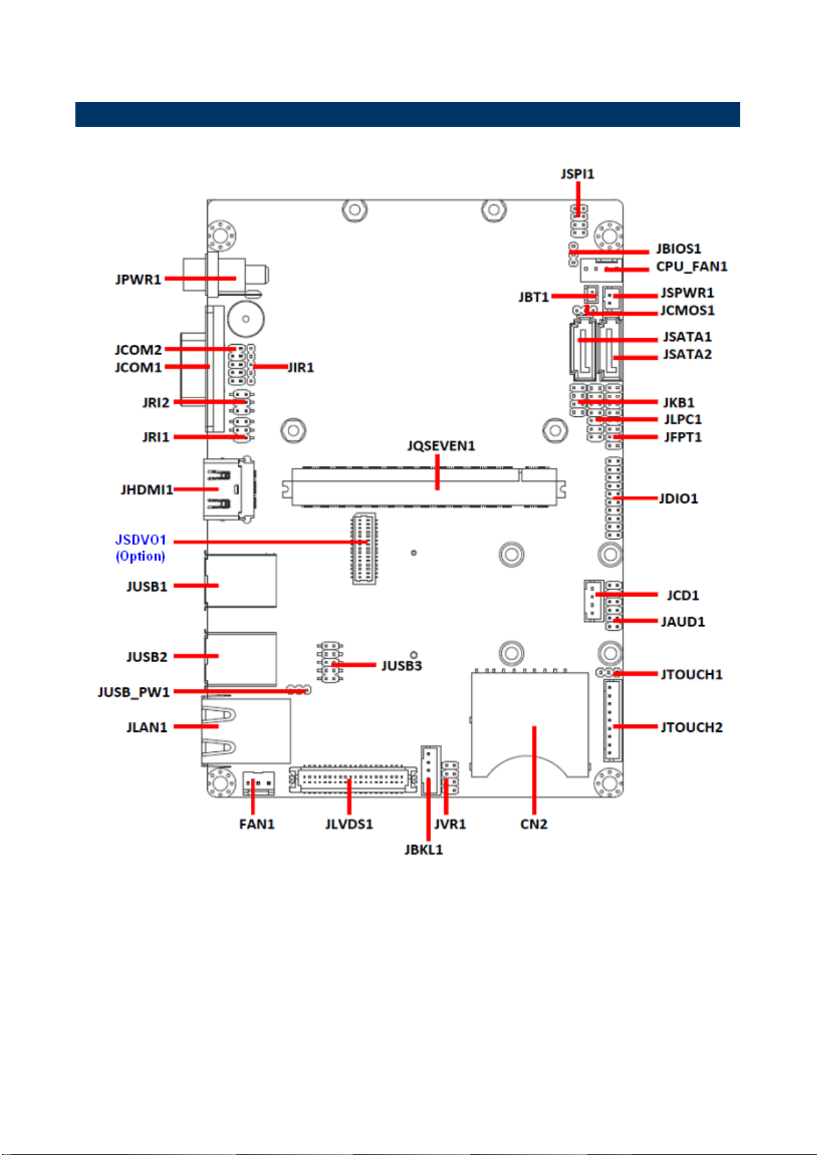
2.1 Product Overview
8 EEV-Q701 Quick Installation Guide
Page 9
Quick Installation Guide
EEV-Q701 Quick Installation Guide 9
Page 10

EEV-Q701
Jumpers
Label
Function
Note
JTOUCH1
Touch selector
3 x 1 header, pitch 2.00mm
JVR1
Brightness adjuster
4 x 2 header, pitch 2.00mm
JUSB_PW1
USB power selector
3 x 1 header, pitch 2.00mm
JFPT1
AT/ATX & Miscellaneous setting connector
8 x 2 header, pitch 2.00mm
JCMOS1
Clear CMOS
3 x 1 header, pitch 2.00mm
JBIOS1
Module/Carrier BIOS selector
3 x 1 header, pitch 2.00mm
JRI1
COM1 Dsub_ 9 signal selector
3 x 2 header, pitch 2.00mm
JRI2
COM2 signal selector
3 x 2 header, pitch 2.00mm
2.2 Jumper and Connector List
You can configure your board to match the needs of your application by setting jumpers. A
jumper is the simplest kind of electric switch.
It consists of two metal pins and a small metal clip (often protected by a plastic cover) that
slides over the pins to connect them. To “close” a jumper you connect the pins with the clip.
To “open” a jumper you remove the clip. Sometimes a jumper will have three pins, labeled 1,
2, and 3. In this case, you would connect either two pins.
The jumper settings are schematically depicted in this manual as follows:
A pair of needle-nose pliers may be helpful when working with jumpers.
Connectors on the board are linked to external devices such as hard disk drives, a
keyboard, or floppy drives. In addition, the board has a number of jumpers that allow you to
configure your system to suit your application.
If you have any doubts about the best hardware configuration for your application, contact
your local distributor or sales representative before you make any changes.
The following tables list the function of each of the board's jumpers and connectors.
10 EEV-Q701 Quick Installation Guide
Page 11

Quick Installation Guide
Connectors
Label
Function
Note
CN2
SDIO connector
SD card slot
JCPU_FAN1
CPU fan connector
4 x 1 wafer, pitch 2.54mm
JBT1
Battery connector
2 x 1 wafer, pitch 2.00mm
FAN1
System Fan connector
3 x 1 wafer, pitch 2.54mm
JAUD1
Audio connector
6 x 2 header, pitch 2.00mm
JBKL1
LCD inverter connector
5 x 1 wafer, pitch 2.0mm
JCD1
CD-ROM audio connector
4 x 1 wafer, pitch 2.00mm
JCOM1
Serial Port 1 connector
D Sub 9 pin male
JCOM2
Serial port 2 in RS-422/485 mode
5 x 2 header, pitch 2.0mm
JDIO1
General purpose I/O connector
10 x 2 header, pitch 2.00mm
JHDMI1
HDMI connector
JIR1
IrDA connector
5 x 1 header, pitch 2.00mm
JKB1
PS/2 keyboard & mouse connector
4 x 2 header, pitch 2.00mm
JLAN1
LAN port connector
JLVDS1
LVDS connector
DIN 40-pin wafer, pitch 1.25mm
JLPC1
LPC connector
7 x 2 header, pitch 2.0mm
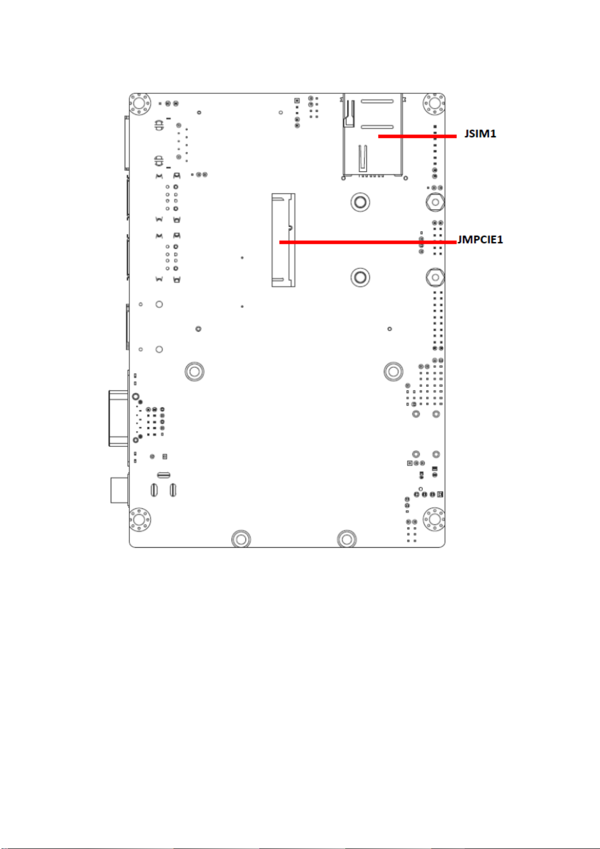
JMPCIE1
MPCIE connector
JPWR1
DC +12V power connector
JQSEVEN1
Qseven connector
JSIM1
SIM card connector
JSPI1
SPI connector
4 x 2 header, pitch 2.0mm
JSPWR1
SATA power connector
2 x 1 wafer, pitch 2.0mm
JSATA1
SATA connector 1
JSATA2
SATA connector 2
JTOUCH2
Touch connector
9 x 1 Wafer, pitch 2.0mm
JUSB1
USB connector 0 &1
JUSB2
USB connector 2 &3
JUSB3
USB connector 4&5
5 x 2 header, pitch 2.0mm
EEV-Q701 Quick Installation Guide 11
Page 12

EEV-Q701
*Default
5W*
4/ 8W
Signal
PIN
Y-
1
SENSE
2
NC
3
*Default
GND*
Signal
PIN
PIN
Signal
+5V
1 2 BK_DC_ADJ
BK_ADJ
3 4 BK_ADJ
GNDC
5 6 BK_PWM_ADJ
BK_ADJ
7 8 LVDS_BKLTCTL
.
2.3 Setting Jumpers & Connectors
2.3.1 Touch selector (JTOUCH1)
2.3.2 Brightness adjuster (JVR1)
12 EEV-Q701 Quick Installation Guide
Page 13

PIN
4-WIRE
5-WIRE
8-WIRE
1
N/A
N/A
Right Sense
2
N/A
N/A
Left Sense
3
N/A
N/A
Bottom Sense
4
N/A
Sense
Top Sense
5
Right
LR
Right Excite
6
Left
LL
Left Excite
7
Bottom
UR
Bottom Excite
8
Top
UL
Top Excite
9
GND
GND
GND
*Default
Default *
Signal
PIN
+V5A
1
USB_VCC_EN
2
+V5S
3
.
2.3.3 Touch connector (JTOUCH2)
Quick Installation Guide
2.3.4 USB power selector (JUSB_PW1)
EEV-Q701 Quick Installation Guide 13
Page 14

EEV-Q701
*Default
Protect*
Clear CMOS
Signal
PIN
+VRTC_IN
1
+VRTC_C
2
GND
3
2.3.5 Clear COMS (JCMOS1)
14 EEV-Q701 Quick Installation Guide
Page 15

*Default
AT*
ATX
Signal
PIN
PIN
Signal
HDD_LED+
1 2 PWR_LED+
HDD_LED#
3 4 PWR_LED-
GND
5 6 Standby_LED+
SYSRST#
7 8 Standby_LED-
GND
9
10
GND
LID_BTN#
11
12
SLP_BTN#
Power Button-
13
14
GND
Power Button-
15
16
AT
2.3.6 AT/ATX & Miscellaneous setting connector (JFPT1)
Quick Installation Guide
EEV-Q701 Quick Installation Guide 15
Page 16

EEV-Q701
*Default
Q7 Module BIOS*
Carrier BIOS
Signal
PIN
+3.3V
1
GND
2
NC
3
Signal
PIN
+5V
2
GND
1
2.3.7 Module/Carrier BIOS selector (JBIOS1)
2.3.8 SATA power connector (JSPWR1)
16 EEV-Q701 Quick Installation Guide
Page 17

* Default
Ring*
+5V
+12V
Signal
PIN
PIN
Signal
PS2
6 5 +12V
PS2
4 3 +5V
NRIA#
2 1 JNRIA#
Note: When switched to “Ring”, the signal only works in RS-232 mode.
2.3.9 COM1 Dsub_ 9 signal selector (JRI1)
Quick Installation Guide
EEV-Q701 Quick Installation Guide 17
Page 18

EEV-Q701
* Default
Ring*
+5V
+12V
Signal
PIN
PIN
Signal
PS3
6 5 +12V
PS3
4 3 +5V
NRIB#
2 1 JNRIB#
2.3.10 Serial port 2 pin9 signal select (JRI2)
18 EEV-Q701 Quick Installation Guide
Page 19

Signal
PIN
PIN
Signal
TX-
1 2 TX+
RX+
3 4 RX-
GND
5 6 DSRB#
RTSB#
7 8 CTSB#
NRIB#
9
10
NC
Signal
PIN
GND
1
+12V
2
CPU_FANIN
3
FANPWMOUT
4
2.3.11 Serial port 2 connector (JCOM2)
Quick Installation Guide
2.3.12 CPU fan connector (JCPU_FAN1)
EEV-Q701 Quick Installation Guide 19
Page 20

EEV-Q701
Signal
PIN
GND
2
+3.3V
1
Signal
PIN
GND
1
+12V
2
SYS_FANIN
3
2.3.13 Battery connector (JBT1)
2.3.14 System Fan connector (FAN1)
20 EEV-Q701 Quick Installation Guide
Page 21

Signal
PIN
PIN
Signal
LINEOUT_R
1 2 LINEOUT_L
GND
3 4 GND
LINE1_RIN
5 6 LINE1_LIN
MIC_RIN
7 8 MIC_LIN
FRONT_JD
9
10
LINE1_JD
MIC1_JD
11
12
GND
JBKL1
Signal
PIN
+5V (max. 2A)
5
BRIGHT
4
BLK_ON
3
GND
2
+12V
1
2.3.15 Audio connector (JAUD1)
Quick Installation Guide
2.3.16 LCD Inverter Connector (JBKL1)
EEV-Q701 Quick Installation Guide 21
Page 22

EEV-Q701
Signal
Signal Description
BRIGHT
Vadj = 0.75V ~ 4.25V (Recommended: 4.7KΩ, >1/16W)
BLK_ON
LCD backlight ON/OFF control signal
Signal
PIN
R_IN
4
GND_IN
3
L_IN
2
GND_IN
1
Note:
For inverters with adjustable Backlight function, it is possible to control the
LCD brightness through the VR signal controlled by JVR1. Please see the
JVR1 (Brightness adjuster) section for detailed circuitry information.
2.3.16.1 Signal Description – LCD Inverter Connector (JBKL1)
2.3.17 CD-ROM Audio Connector (JCD1)
22 EEV-Q701 Quick Installation Guide
Page 23
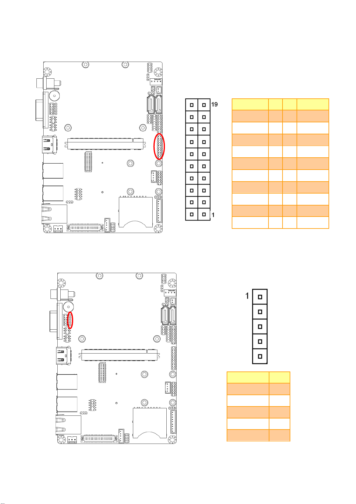
Signal
PIN
PIN
Signal
+5V
20
19
GND
SMB_DATA
18
17
SMB_CLK
DO7
16
15
DI7
DO6
14
13
DI6
DO5
12
11
DI5
DO4
10
9
DI4
DO3
8
7
DI3
DO2
6
5
DI2
DO1
4 3 DI1
DO0
2 1 DI0
Signal
PIN
+5V
1
NC
2
INB_IRRX
3
GND
4
OUTB_IRTX
5
2.3.18 General Purpose I/O Connector (JDIO1)
Quick Installation Guide
2.3.19 IrDA Connector (JIR1)
EEV-Q701 Quick Installation Guide 23
Page 24

EEV-Q701
Signal
PIN
PIN
Signal
KBDA
1 2 KBCK
GND_PS2
3 4 VCC_PS2
MSDA
5
6
MSCK
NC
7
Signal
PIN
PIN
Signal
LPC_AD0
1 2 +3.3V
LPC_AD1
3 4 PCIE_RST#
LPC_AD2
5 6 LPC_FRAME#
LPC_AD3
7 8 LPC_CLK
SERIRQ
9
10
GND
+5V
11
12
GND
+5VSB
13
14
GND
2.3.20 PS/2 keyboard & mouse connector (JKB1)
2.3.21 LPC Connector (JLPC1)
24 EEV-Q701 Quick Installation Guide
Page 25

Signal
PIN
PIN
Signal
+3.3V
1 2 +5V
+3.3V
3 4 +5V
LVDS_DDC_CLK
5 6 LVDS_DDC_DATA
GND
7 8 GND
LVDSA_DATA1
9
10
LVDSA_DATA0
LVDSA_DATA1#
11
12
LVDSA_DATA0#
GND
13
14
GND
LVDSA_DATA3
15
16
LVDSA_DATA2
LVDSA_DATA3#
17
18
LVDSA_DATA2#
GND
19
20
GND
LVDSB_DATA1
21
22
LVDSB_DATA0
LVDSB_DATA1#
23
24
LVDSB_DATA0#
GND
25
26
GND
LVDSB_DATA3
27
28
LVDSB_DATA2
LVDSB_DATA3#
29
30
LVDSB_DATA2#
GND
31
32
GND
LVDSB_CLK
33
34
LVDSA_CLK
LVDSB_CLK#
35
36
LVDSA_CLK#
GND
37
38
GND
+12V
39
40
+12V
2.3.22 LVDS connector (JLVDS1)
Quick Installation Guide
EEV-Q701 Quick Installation Guide 25
Page 26

EEV-Q701
Signal
PIN
PIN
Signal
+3.3V
1 2 GND
CS#
3 4 CLK_C
SO_C
5
6
SI_C
HOLD#
7
8
NC
Signal
PIN
PIN
Signal
+5V
1 2 GND
USB_N4
3 4 GND
USB_P4
5 6 USB_P5
GND
7 8 USB_N5
GND
9
10
+5V
2.3.23 SPI connector (JSPI1)
2.3.24 USB Connector 4 & 5 (JUSB3)
26 EEV-Q701 Quick Installation Guide
Page 27

Signal
PIN
PIN
Signal
GND7
39
40
GND8
BIOS_DISABLE#
41
42
SDIO_CLK#
SDIO_CD#
43
44
SDIO_LED
SDIO_CMD
45
46
SDIO_WP
SDIO_PWR#
47
48
SDIO_DAT1
SDIO_DAT0
49
50
SDIO_DAT3
SDIO_DAT2
51
52
SDIO_DAT5
SDIO_DAT4
53
54
SDIO_DAT7
SDIO_DAT6
55
56
RSVD56
GND9
57
58
GND10
HDA_SYNC
59
60
SMB_CLK
HDA_RST#
61
62
SMB_DAT
HDA_BCLK
63
64
SMB_ALERT#
HDA_SDI
65
66
I2C_CLK
HDA_SDO
67
68
I2C_DAT
THRM#
69
70
WDTRIG#
THRMTRIP#
71
72
WDOUT
GND11
73
74
GND12
USB_P7-
75
76
USB_P6
USB_P7+
77
78
USB_P6
USB_6_7_OC#
79
80
USB_4_5_OC#
USB_P5-
81
82
USB_P4-
USB_P5+
83
84
USB_P4+
USB_2_3_OC#
85
86
USB_0_1_OC#
USB_P3-
87
88
USB_P2-
USB_P3+
89
90
USB_P2+
USB_HOST_PRES#
91
92
USB_HC_SEL
USB_P1-
93
94
USB_P0-
USB_P1+
95
96
USB_P0+
GND13
97
98
GND14
LVDS_A0+
99
100
LVDS_B0+
LVDS_A0-
101
102
LVDS_B0-
LVDS_A1+
103
104
LVDS_B1+
Signal
PIN
PIN
Signal
GND1
1 2 GND2
GBE_MDI3-
3 4 GBE_MDI2-
GBE_MDI3+
5 6 GBE_MDI2+
GBE_LINK100#
7 8 GBE_LINK1000#
GBE_MDI1-
9
10
GBE_MDI0-
GBE_MDI1+
11
12
GBE_MDI0+
GBE_LINK#
13
14
GBE_ACT#
GBE_CTREF
15
16
SUS_S5#
WAKE#
17
18
SUS_S3#
SUS_STAT#
19
20
PWRBTN#
SLP_BTN#
21
22
LID_BTN#
GND3
23
24
GND4
GND5
25
26
PWGIN
BATLOW#
27
28
RSTBTN#
SATA0_TX+
29
30
SATA1_TX+
SATA0_TX-
31
32
SATA1_TX-
SATA_ACT#
33
34
GND6
SATA0_RX+
35
36
SATA1_RX+
SATA0_RX-
37
38
SATA1_RX-
2.3.25 Qseven connector (JQSEVEN1)
Quick Installation Guide
EEV-Q701 Quick Installation Guide 27
Page 28

EEV-Q701
Signal
PIN
PIN
Signal
LVDS_A1-
105
106
LVDS_B1-
LVDS_A2+
107
108
LVDS_B2+
LVDS_A2-
109
110
LVDS_B2-
LVDS_PPEN
111
112
LVDS_BLEN
LVDS_A3+
113
114
LVDS_B3+
LVDS_A3-
115
116
LVDS_B3
GND15
117
118
GND16
LVDS_A_CLK+
119
120
LVDS_B_CLK+
LVDS_A_CLK-
121
122
LVDS_B_CLK-
LVDS_BLT_CTRL
123
124
RSVD124
LVDS_DID_DAT
125
126
LVDS_BLC_DAT
LVDS_DID_CLK
127
128
LVDS_BLC_CLK
RSVD129
129
130
RSVD130
SDVO_BCLK+
131
132
SDVO_INT+
SDVO_BCLK-
133
134
SDVO_INT-
GND17
135
136
GND18
SDVO_GREEN+
137
138
SDVO_FLDSTALL+
SDVO_GREEN-
139
140
SDVO_FLDSTALL-
GND19
141
142
GND20
SDVO_BLUE+
143
144
SDVO_TVCLKIN+
SDVO_BLUE-
145
146
SDVO_TVCLKIN-
GND21
147
148
GND22
SDVO_RED+
149
150
SDVO_CTRL_DAT
SDVO_RED-
151
152
SDVO_CTRL_CLK
HDMI_HPD#
153
154
DP_HPD#
PCIE_CLK_REF+
155
156
PCIE_WAKE#
PCIE_CLK_REF-
157
158
PCIE_RST#
GND23
159
160
GND24
PCIE3_TX+
161
162
PCIE3_RX+
PCIE3_TX-
163
164
PCIE3_RX-
GND25
165
166
GND26
PCIE2_TX+
167
168
PCIE2_RX+
PCIE2_TX-
169
170
PCIE2_RX-
Signal
PIN
PIN
Signal
EXCD0_PERST#
171
172
EXCD1_PERST#
PCIE1_TX+
173
174
PCIE1_RX+
PCIE1_TX-
175
176
PCIE1_RX-
EXCD0_CPPE#
177
178
EXCD1_CPPE#
PCIE0_TX+
179
180
PCIE0_RX+
PCIE0_TX-
181
182
PCIE0_RX-
GND27
183
184
GND28
LPC_AD0
185
186
LPC_AD1
LPC_AD2
187
188
LPC_AD3
LPC_CLK
189
190
LPC_FRAME#
SERIRQ
191
192
LPC_LDRQ#
VCC_RTC
193
194
SPKR
FAN_TACHOIN
195
196
FAN_PWMOUT
GND29
197
198
GND30
RSVD199
199
200
RSVD200
RSVD201
201
202
RSVD202
RSVD203
203
204
MFG_NC4
VCC_5V_SB1
205
206
VCC_5V_SB2
MFG_NC0
207
208
MFG_NC2
MFG_NC1
209
210
MFG_NC3
VCC1
211
212
VCC2
VCC3
213
214
VCC4
VCC5
215
216
VCC6
VCC7
217
218
VCC8
VCC9
219
220
VCC10
VCC11
221
222
VCC12
VCC13
223
224
VCC14
VCC15
225
226
VCC16
VCC17
227
228
VCC18
VCC19
229
230
VCC20
28 EEV-Q701 Quick Installation Guide
 Loading...