

Page 1

EEV-EX20
Micro-ATX XTX Carrier Board
Quick Installation Guide
1st Ed – 11 January 2010
Part No. E2017EX2000R
Page 2

EEV-EX20
FCC Statement
THIS DEVICE COMPLIES WITH PART 15 FCC RULES. OPERATION IS
SUBJECT TO THE FOLLOWING TWO CONDITIONS:
(1) THIS DEVICE MAY NOT CAUSE HARMFUL INTERFERENCE.
(2) THIS DEVICE MUST ACCEPT ANY INTERFERENCE RECEIVED INCLUDING
INTERFERENCE THAT MAY CAUSE UNDESIRED OPERATION.
THIS EQUIPMENT HAS BEEN TESTED AND FOUND TO COMPLY WITH THE LIMITS
FOR A CLASS "A" DIGITAL DEVICE, PURSUANT TO PART 15 OF THE FCC RULES.
THESE LIMITS ARE DESIGNED TO PROVIDE REASONABLE PROTECTION AGAINST
HARMFUL INTERFERENCE WHEN THE EQUIPMENT IS OPERATED IN A
COMMERCIAL ENVIRONMENT. THIS EQUIPMENT GENERATES, USES, AND CAN
RADIATE RADIO FREQUENCY ENERGY AND, IF NOT INSTALLED AND USED IN
ACCORDANCE WITH THE INSTRUCTION MANUAL, MAY CAUSE HARMFUL
INTERFERENCE TO RADIO COMMUNICATIONS.
OPERATION OF THIS EQUIPMENT IN A RESIDENTIAL AREA IS LIKELY TO CAUSE
HARMFUL INTERFERENCE IN WHICH CASE THE USER WILL BE REQUIRED TO
CORRECT THE INTERFERENCE AT HIS OWN EXPENSE.
Copyright Notice
Copyright © 2010 Avalue Technology Inc., ALL RIGHTS RESERVED.
No part of this document may be reproduced, copied, translated, or transmitted in any form
or by any means, electronic or mechanical, for any purpose, without the prior written
permission of the original manufacturer.
Trademark Acknowledgement
Brand and product names are trademarks or registered trademarks of their respective
owners.
2 EEV-EX20 Quick Installation Guide
Page 3

Quick Installation Guide
Contents
1. Getting Started...........................................................................................................5
1.1 Safety Precautions ................................................................................................5
1.2 Packing List...........................................................................................................5
2. Hardware Configuration............................................................................................6
2.1 Product Overview..................................................................................................7
2.2 Jumper and Connector List ...................................................................................8
2.3 Setting Jumpers & Connectors............................................................................11
2.3.1 Module codec MIC mode select (J1)....................................................................................... 11
2.3.2 JCOM2 pin 9 signal select (JRI1)............................................................................................ 11
2.3.3 Miscellaneous setting connector (JFP1) ................................................................................. 12
2.3.4 JCOM2 RS232/422/485 mode select (JP1)............................................................................ 13
2.3.5 Serial Port 2 in RS-232 mode (JCOM2).................................................................................. 14
2.3.6 Serial port 2 in RS-422/485 mode (JRS422/485).................................................................... 15
2.3.7 Audio Codec select (JP3)........................................................................................................15
2.3.8 Auto power on enable (JP5).................................................................................................... 16
2.3.9 AT/ATX mode select (JP7)...................................................................................................... 16
2.3.10 Clear COMS (JP4)................................................................................................................... 17
2.3.11 Carrier board Audio Codec Enable (JP6)................................................................................ 17
2.3.12 Module LPT/ FLOPPY Mode Select (JP2).............................................................................. 18
2.3.13 AT Power Connector (AT1)..................................................................................................... 19
2.3.14 ATX Power Connector (ATX1)................................................................................................ 19
2.3.15 SMBus connector (CN10) ....................................................................................................... 20
2.3.16 I2C connector (CN11).............................................................................................................. 20
2.3.17 (Module Codec) Audio Amp. Left/ Right out channel out (CN5/ CN6).................................... 21
2.3.18 (Carrier board codec) S/PDIF connector (CN8)...................................................................... 21
2.3.19 CPU fan connector (CPUFAN1).............................................................................................. 22
2.3.20 System fan connector (FAN1/ FAN2)...................................................................................... 22
2.3.21 (Carrier board codec) Audio connector (JAUDIO1) ................................................................ 23
2.3.22 Floppy connector (FLP1).........................................................................................................24
2.3.23 Primary/ Secondary IDE Connector (IDE1/IDE2).................................................................... 25
2.3.24 (Carrier board Codec) LCD Inverter Connector (JBKL1)........................................................ 26
2.3.25 Inverter +12V Connector (JBKL2)........................................................................................... 26
2.3.26 (Module Codec) LCD Inverter Connector (JBKL3).................................................................. 27
2.3.27 CD-ROM audio Connector 1/ 2 (JCD1/ JCD2)........................................................................ 27
2.3.28 General Purpose I/O Connector (JDIO1)................................................................................ 28
2.3.29 IrDA Connector (JIR1)............................................................................................................. 28
2.3.30 LPC Connector (JLPC1).......................................................................................................... 29
EEV-EX20 Quick Installation Guide 3
Page 4

EEV-EX20
2.3.31 USB Connector 4 & 5 (JUSB1) ............................................................................................... 29
2.3.32 LVDS connector (JLVDS1)...................................................................................................... 30
2.3.33 TV Out Connector (JTV1)........................................................................................................ 31
2.3.34 LED Connector (WLED1)........................................................................................................ 32
2.3.35 Serial port 1/ 2 connector (TTL1/ TTL2).................................................................................. 32
4 EEV-EX20 Quick Installation Guide
Page 5
Quick Installation Guide
1. Getting Started
1.1 Safety Precautions
Warning!
Always completely disconnect the power cord from your
chassis whenever you work with the hardware. Do not
make connections while the power is on. Sensitive
electronic components can be damaged by sudden power
surges. Only experienced electronics personnel should
open the PC chassis.
Caution!
Always ground yourself to remove any static charge before
touching the CPU card. Modern electronic devices are very
sensitive to static electric charges. As a safety precaution,
use a grounding wrist strap at all times. Place all electronic
components in a static-dissipative surface or static-shielded
bag when they are not in the chassis.
1.2 Packing List
Before you begin installing your single board, please make sure that the
following materials have been shipped:
z 1 x EEV-EX20 Micro-ATX XTX Carrier Board
z 1 x Quick Installation Guide
z 1 x CD-ROM or DVD-ROM contains the followings:
— User’s Manual (this manual in PDF file)
— Audio drivers and utilities
EEV-EX20 Quick Installation Guide 5
Page 6

EEV-EX20
2. Hardware
Configuration
6 EEV-EX20 Quick Installation Guide
Page 7
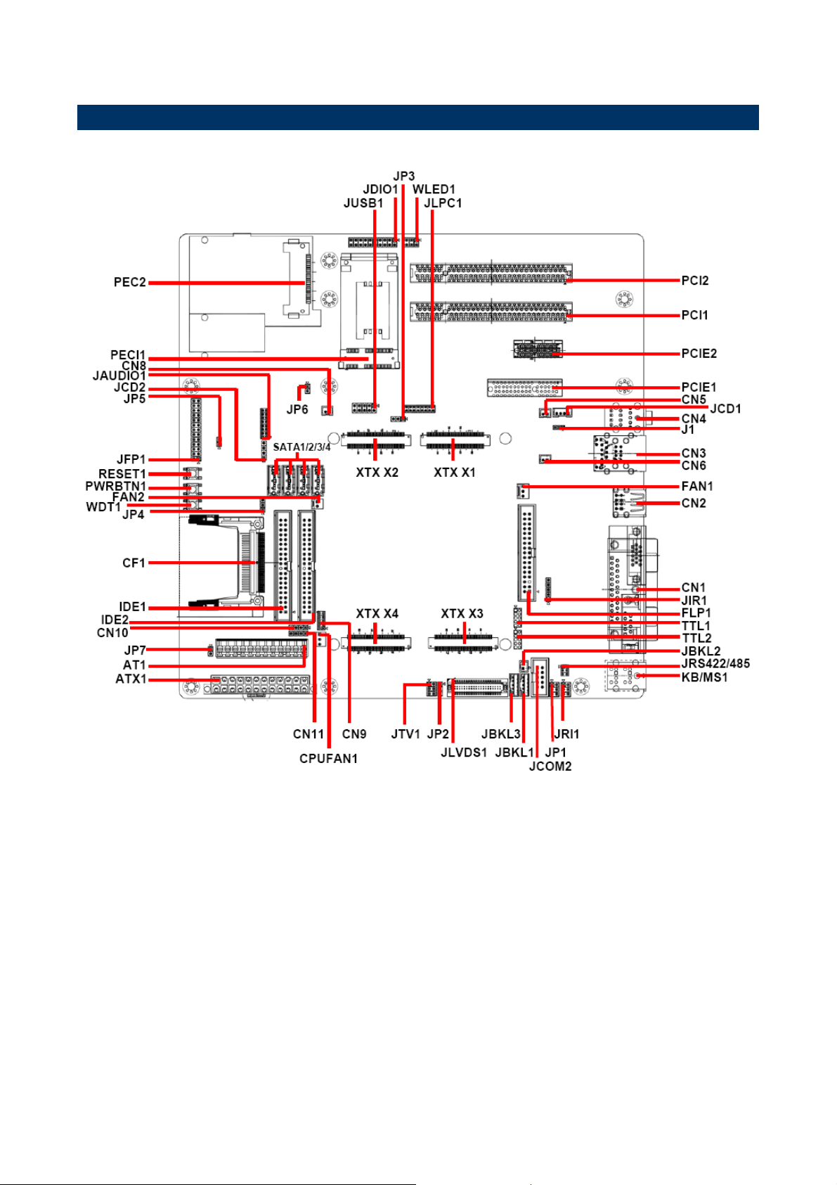
2.1 Product Overview
Quick Installation Guide
EEV-EX20 Quick Installation Guide 7
Page 8
EEV-EX20
2.2 Jumper and Connector List
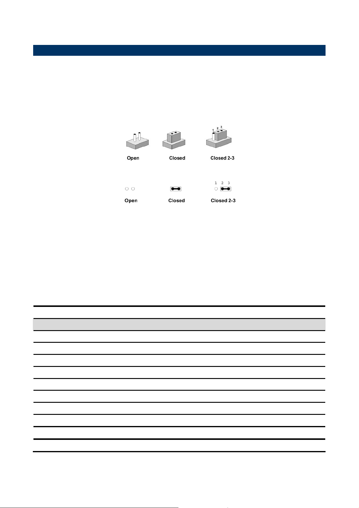
You can configure your board to match the needs of your application by setting jumpers. A
jumper is the simplest kind of electric switch.
It consists of two metal pins and a small metal clip (often protected by a plastic cover) that
slides over the pins to connect them. To “close” a jumper you connect the pins with the clip.
To “open” a jumper you remove the clip. Sometimes a jumper will have three pins, labeled 1,
2, and 3. In this case, you would connect either two pins.
The jumper settings are schematically depicted in this manual as follows:
A pair of needle-nose pliers may be helpful when working with jumpers.
Connectors on the board are linked to external devices such as hard disk drives, a
keyboard, or floppy drives. In addition, the board has a number of jumpers that allow you to
configure your system to suit your application.
If you have any doubts about the best hardware configuration for your application, contact
your local distributor or sales representative before you make any changes.
The following tables list the function of each of the board's jumpers and connectors.
Jumpers
Label Function Note
J1
JFP1
JP1
JP2
JP3
Module Codec MIC mode select 3 x 1 header, pitch 2.0mm
Miscellaneous setting connector 13 x 2 header, pitch 2.54mm
JCOM2 in RS-232/422/485 mode select 3 x 2 header, pitch 2.54mm
Module LPT/ FLOPPY Mode Select 3 x 1 header, pitch 2.54mm
Audio Codec select 3 x 1 header, pitch 2.54mm
JP4
JP5
JP6
JP7
JRI1
8 EEV-EX20 Quick Installation Guide
Clear CMOS 3 x 1 header, pitch 2.54mm
Auto power on enable 2 x 1 header, pitch 2.54mm
Carrier board audio power connector 2 x 1 header, pitch 2.54mm
AT/ ATX mode select 2 x 1 header, pitch 2.54mm
JCOM2 pin 9 signal select 3 x 2 header, pitch 2.54mm
Page 9

Quick Installation Guide
Connectors
Label Function Note
AT1
ATX1
CF1
CN1-2
CN1-3
CN1-1
CN2
CN3-1
CN3-2
CN4
CN5
CN6
CN7
AT power connector 12 x 1 wafer, pitch 3.96mm
ATX power connector 12 x 2 wafer, pitch 4.2mm
Compact Flash card connector
Serial port 1 connector D-sub 9-pin, male
VGA connector D-sub 15-pin, female
Print port D-sub 25-pin, female
USB connector 2 & 3 Double deck
LAN port connector
USB connector 0 & 1
Audio connector (use module codec)
Audio AMP, left out connector (use module
2 x 1 wafer, pitch 2.0mm
codec)
Audio AMP, right out connector (use module
2 x 1 wafer, pitch 2.0mm
codec)
(Reserved)
CN8
CN9
CN10
CN11
CPUFAN1
FAN1
FAN2
FLP1
IDE1
IDE2
JAUDIO1
JBKL1
JBKL2
JBKL3
S/PDIF connector (use carrier board codec) 2 x 1 wafer, pitch 2.0mm
(Reserved) 5 x 2 header, pitch 2.0mm
SMBus connector 4 x 1 header, pitch 2.54mm
I2C connector 4 x 1 header, pitch 2.54mm
CPU fan connector 3 x 1 wafer, pitch 2.54mm
System fan connector 1 3 x 1 wafer, pitch 2.54mm
System fan connector 2 2 x 1 wafer, pitch 2.54mm
Floppy connector 17 x 2 wafer, pitch 2.54mm
Primary IDE connector 1 20 x 2 wafer, pitch 2.54mm
Secondary IDE connector 2 20 x 2 wafer, pitch 2.54mm
Audio connector (use carrier board codec) 8 x 2 header, pitch 2.0mm
LCD inverter connector (use carrier board
5 x 1 wafer, pitch 2.0mm
codec)
Inverter +12V connector 5 x 1 wafer, pitch 2.0mm
LCD inverter connector (use module codec) 2 x 1 wafer, pitch 2.0mm
JCD1
JCD2
CD-ROM audio in (use module codec) 4 x 1 wafer, pitch 2.0mm
CD-ROM audio in (use carrier board codec) 4 x 1 header, pitch 2.54mm
EEV-EX20 Quick Installation Guide 9
Page 10

EEV-EX20
Connectors
Label Function Note
JCOM1
JDIO1
JIR1
JLPC1
JLVDS1
JRS422/485
JTV1
JUSB1
KB/MS1
TTL1
Serial Port 2 in RS-232 mode 5 x 2 header, pitch 2.54mm
10 x 2 header, pitch
General purpose I/O connector
2.54mm
IrDA connector 5 x 1 header, pitch 2.54mm
LPC connector 8 x 2 header, pitch 2.0mm
DIN 40-pin wafer, pitch
LVDS connector
1.25mm
Serial port 2 in RS-422/485 mode 3 x 2 header, pitch 2.0mm
TV out connector 3 x 2 header, pitch 2.54mm
USB connector 4 & 5 5 x 2 header, pitch 2.54mm
PS/2 keyboard & mouse connector
Serial port 1 connector (TTL level) 5 x 2 head er, pitch 2.0mm
TTL2
PCI1/2
PCIE1/2
PEC1
PCE2
PWRBTN1
RESET1
SATA1/2/3/4
WDT1
WLED1
XTX X1/2/3/4
Serial port 2 connector (TTL level) 5 x 2 head er, pitch 2.0mm
PCI slot 1/2
PCIE slot 1/2
Mini PCI-e slot
PCI express card slot
Power button connector
Reset button connector
Serial ATA connector1/2/3/4
Watch dog in
Mini PCIe LED connector 3 x 2 header, pitch 2.54mm
XTX connector 1/ 2/ 3/ 4
10 EEV-EX20 Quick Installation Guide
Page 11

2.3 Setting Jumpers & Connectors
2.3.1 Module codec MIC mode select (J1)
Quick Installation Guide
5.1-channel center out
MIC signal in*
*Default
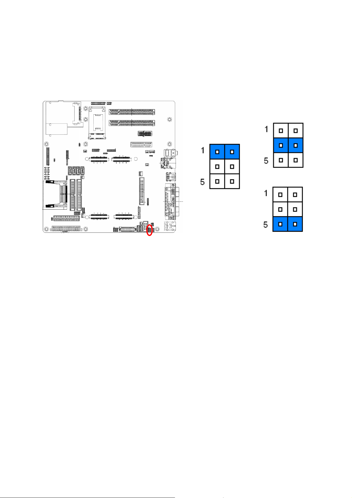
2.3.2 JCOM2 pin 9 signal select (JRI1)
Note:
Use to switch CN4 MIC phone Jack mode.
Ring*
+12V
+5V
* Default
EEV-EX20 Quick Installation Guide 11
Page 12

EEV-EX20
Note: When switch to “Ring”, the signal only works in RS-232 mode.
2.3.3 Miscellaneous setting connector (JFP1)
Signal PIN PIN Signal
*Default
Master*
CF Set 26 25
LVDS
BRIGHT
LVDS
CF Set 24 23
BRIGHT
LVDS
CF Set 22 21
BRIGHT
NC 20 19 NC
NC 18 17 NC
External SPEAK 16 15 KB LOCKExternal SPEAK 14 13 KB LOCK+
Slave
POWER
Suspend LED- 12 11
BUTTON-
POWER
Suspend LED+ 10 9
BUTTON+
POWER ON LED- 8 7 IDE LED-
POWER ON LED+ 6 5 IDE LED+
12 EEV-EX20 Quick Installation Guide
STANDBY LED- 4 3 RESET
STANDBY LED+ 2 1 RESET
Page 13
2.3.4 JCOM2 RS232/422/485 mode select (JP1)
Quick Installation Guide
* Default
RS422
RS232*
RS485
EEV-EX20 Quick Installation Guide 13
Page 14
EEV-EX20
2.3.5 Serial Port 2 in RS-232 mode (JCOM2)
Signal PIN PIN Signal
DCD2 1 2 RxDD2
TxDD2 3 4 DTR2
GND 5 6 DSR2
RTS2 7 8 CTS2
RI2 9 10 NC
1. When JP1 is in RS-422/482 mode,
2. For more details about Pin9, please
Note:
JCOM1 is inaction.
refer to JRI1.
14 EEV-EX20 Quick Installation Guide
Page 15

2.3.6 Serial port 2 in RS-422/485 mode (JRS422/485)
Signal PIN PIN Signal
TX- 1 2 RXTX+ 3 4 RX+
+5V 5 6 GND
Quick Installation Guide
In 422 mode
In 485 mode
2.3.7 Audio Codec select (JP3)
Signal PIN PIN Signal
DATA- 1 2 NC
DATA+ 3 4 NC
+5V 5 6 GND
Module Audio Codec*
Carrier Audio Codec
* Default
EEV-EX20 Quick Installation Guide 15
Page 16

EEV-EX20
2.3.8 Auto power on enable (JP5)
* Default
On for AT
OFF for ATX*
2.3.9 AT/ATX mode select (JP7)
* Default
AT
ATX*
16 EEV-EX20 Quick Installation Guide
Page 17

2.3.10 Clear COMS (JP4)
Quick Installation Guide
Protect*
Clear CMOS
2.3.11 Carrier board Audio Codec Enable (JP6)
Disable
Enable*
EEV-EX20 Quick Installation Guide 17
Page 18

EEV-EX20
2.3.12 Module LPT/ FLOPPY Mode Select (JP2)
LPT mode*
Floppy mode
Note:
After switch this jumper, please run into BIOS CMOS
Setup to select the LPT/Floppy mode in onboard LPT port
mode.
18 EEV-EX20 Quick Installation Guide
Page 19
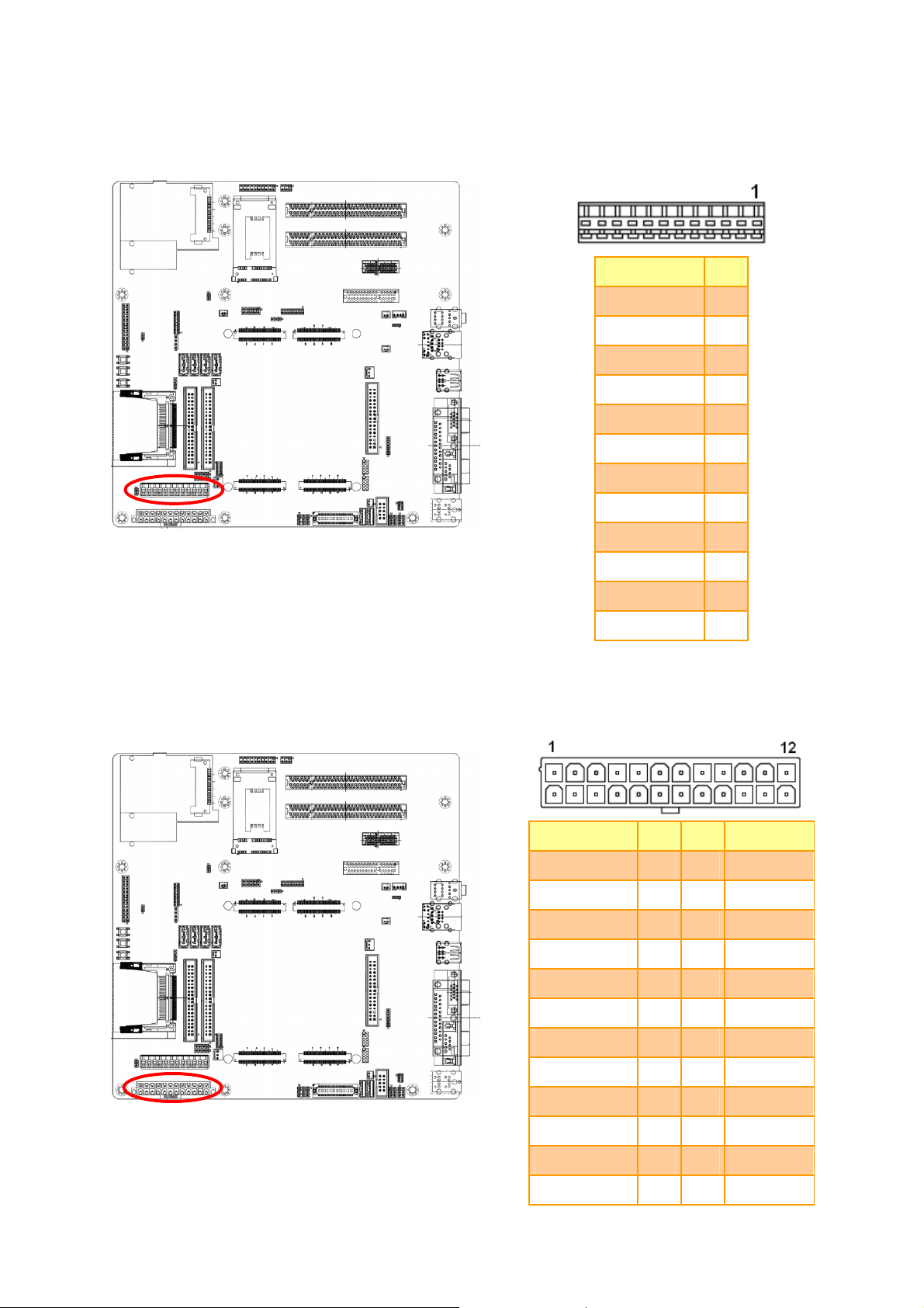
2.3.13 AT Power Connector (AT1)
Quick Installation Guide
Signal PIN
PWROK 1
+5V 2
+12V 3
-12V 4
GND 5
GND 6
GND 7
GND 8
-5V 9
2.3.14 ATX Power Connector (ATX1)
+5V 10
+5V 11
+5V 12
Signal PIN PIN Signal
+3.3V 1 13 +3.3V
+3.3V 2 14 -12V
GND 3 15 GND
+5V 4 16 PS_ON
GND 5 17 GND
+5V 6 18 GND
GND 7 19 GND
PWROK 8 20 -5V
AUX5V 9 21 +5V
+12V 10 22 +5V
+12V 11 23 +5V
+3.3V 12 24 GND
EEV-EX20 Quick Installation Guide 19
Page 20

EEV-EX20
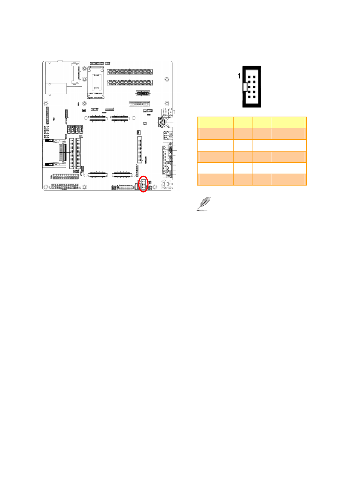
2.3.15 SMBus connector (CN10)
CN10
Signal PIN
+5V 1
SMBCLK 2
SMBDAT 3
GND 4
2.3.16 I2C connector (CN11)
CN11
Signal PIN
+5V 1
12CLK 2
12DAT 3
GND 4
20 EEV-EX20 Quick Installation Guide
Page 21

Quick Installation Guide
2.3.17 (Module Codec) Audio Amp. Left/ Right out channel out (CN5/ CN6)
CN5
CN6
AMP_LOUT+/ AMP_ROUT+ 1
AMP_LOUT-/ AMP_ROUT- 2
2.3.18 (Carrier board codec) S/PDIF connector (CN8)
Signal PIN
Signal PIN
S/PDIF in 1
S/PDIF out 2
EEV-EX20 Quick Installation Guide 21
Page 22

EEV-EX20
2.3.19 CPU fan connector (CPUFAN1)
Signal PIN
GND 1
Fan power (Max. +12V) 2
Fan Tachomater Input 3
Note:
The CPU Fan speed could be controlled by
2.3.20 System fan connector (FAN1/ FAN2)
FAN1
FAN2
module via FAN_PWMOUT (XTX X2 Pin-92)
signal.
FAN1
FAN2
Signal PIN
GND 1
Signal PIN
GND 1
22 EEV-EX20 Quick Installation Guide
+12V 2
NC 3
+5V 2
Page 23

2.3.21 (Carrier board codec) Audio connector (JAUDIO1)
Signal PIN PIN Signal
SIDE_OUT_L 16 15 SIDE_OUT_R
Quick Installation Guide
SUR_OUT_L 14 13 SUR_OUT_R
CEN_OUT 12 11 LFE_OUT
SENSEB 10 9 SENSEA
MIC_REF 8 7 MIC_IN
LINEIN_L 6 5 LINEIN_R
GND 4 3 GND
LINEOUT_L 2 1 LINEOUT_R
EEV-EX20 Quick Installation Guide 23
Page 24

EEV-EX20
2.3.22 Floppy connector (FLP1)
Signal PI36N PIN Signal
DSKCHG 34 33 GND
SIDE1 32 31 GND
RDATA 30 29 NC
WPT 28 27 GND
TK00 26 25 GND
WGATE 24 23 GND
WDATA 22 21 GND
STEP 20 19 GND
DIR 18 17 GND
MOTEB 16 15 GND
DRVSA 14 13 GND
DRVSB 12 11 GND
MOTSA 10 9 GND
INDEX 8 7 GND
NC 6 5 GND
NC 4 3 GND
REDWC 2 1 GND
24 EEV-EX20 Quick Installation Guide
Page 25

2.3.23 Primary/ Secondary IDE Connector (IDE1/IDE2)
Quick Installation Guide
IDE1
IDE2
Signal PIN PIN Signal
GND 40 39 HD_LED1/HD_LED2
HCS#3/QDCS3 38 37 HDCS1/QDCS#1
HDA2/QDA2 36 35 HDA0/QDA0
DMA100/SPDIAG_S 34 33 HDA1/QDA1
NC 32 31 HIRQ/QIRQ
GND 30 29 HDACK/QDACK
GND 28 27 HDIRDY/QIORDY
GND 26 25 HDIOR/QIOR
GND 24 23 HDIOW/QIOW
GND 22 21 HDREQ/QDREQ
20 19 GND
HP15/HQ15 18 17 HP0/HQ0
HP14/HQ14 16 15 HP1/HQ1
HP13/HQ13 14 13 HP2/HQ2
HP12/HQ12 12 11 HP3/HQ3
HP11/HQ11 10 9 HP4/HQ4
HP10/HQ10 8 7 HP5/HQ5
HP9/HQ9 6 5 HP6/HQ6
HP8/HQ8 4 3 HP7/HQ7
GND 2 1 HDRST
EEV-EX20 Quick Installation Guide 25
Page 26

EEV-EX20
2.3.24 (Carrier board Codec) LCD Inverter Connector (JBKL1)
Signal PIN
JBKL1
JBKL2
JBKL1 JBKL3
+5V (max. 2A) 5
BRIGHT 4
BLK_ON 3
GND 2
+12V (max. 2A) 1
2.3.24.1 Signal Description – LCD Inverter Connector (JBKL1/ JBKL3)
Signal Signal Description
BRIGHT
BLK_ON LCD backlight ON/OFF control signal
Wire from JFP1 Pin 23, If there is a Variable Resistor (Recommended :4.7Kohm,
>1/16W) connect on JFP1 Pin21,23,25, the voltage adjust range is 0.75V ~ 4.25V.
2.3.25 Inverter +12V Connector (JBKL2)
JBKL2
26 EEV-EX20 Quick Installation Guide
JBKL2
Signal PIN
GND 2
+12V 1
JBKL1 JBKL3
Page 27

2.3.26 (Module Codec) LCD Inverter Connector (JBKL3)
Quick Installation Guide
JBKL3
Signal PIN
JBKL2
JBKL1 JBKL3
2.3.27 CD-ROM audio Connector 1/ 2 (JCD1/ JCD2)
+5V (max. 2A) 5
BRIGHT 4
NC 3
GND 2
+12V (max. 2A) 1
JCD2
JCD1
Note:
JCD1 is for module codec. JCD2 is for carrier codec.
Signal PIN
GND 1
LINEL 2
GND 3
LINER 4
Signal PIN
CD_L 4
GND 3
GND 2
CD_R 1
EEV-EX20 Quick Installation Guide 27
Page 28
EEV-EX20
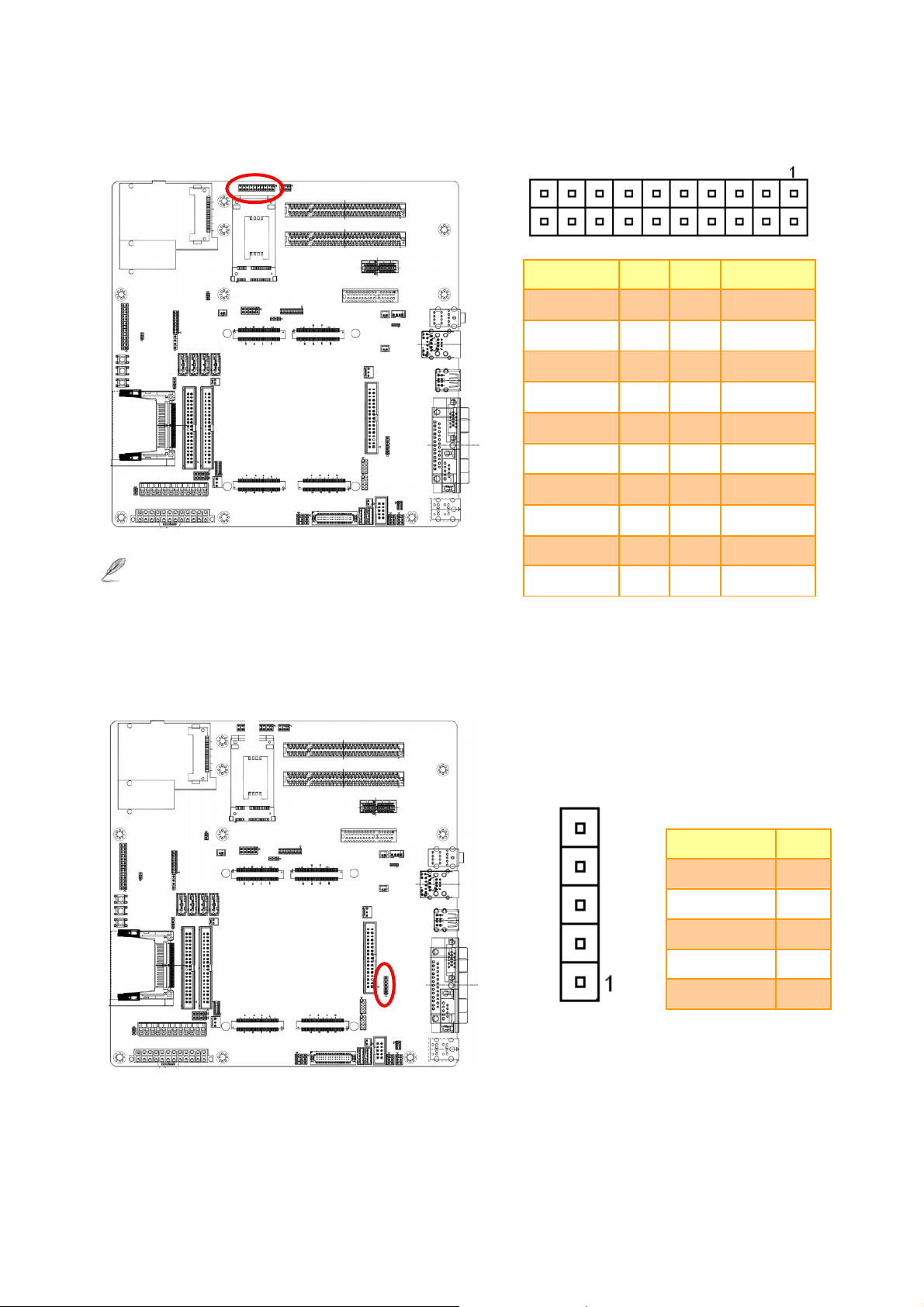
2.3.28 General Purpose I/O Connector (JDIO1)
Signal PIN PIN Signal
DIO0 1 2 DIO10
DIO1 3 4 DIO11
DIO2 5 6 DIO12
DIO3 7 8 DIO13
DIO4 9 10 DIO14
DIO5 11 12 DIO15
DIO6 13 14 DIO16
Note:
There is no pull-up resistor on those GPI/O pin.
2.3.29 IrDA Connector (JIR1)
DIO7 15 16 DIO17
SMBCLK 17 18 SMBDAT
GND 19 20 +5V
Signal PIN
IRTX 5
GND 4
IRRX 3
NC 2
28 EEV-EX20 Quick Installation Guide
+5V 1
Page 29

2.3.30 LPC Connector (JLPC1)
Quick Installation Guide
Signal PIN PIN Signal
LPC_AD0 1 2 +3.3V
LPC_AD1 3 4 PCI_RST#_P
LPC_AD2 5 6 LPC_FRAME#
LPC_AD3 7 8 PCICLK3
SERIRQ 9 10 GND
LPC_DRQ0# 11 12 LPC_DRQ1#
+5V 13 14 GND
VCCSB 15 16 GND
2.3.31 USB Connector 4 & 5 (JUSB1)
Signal PIN PIN Signal
USBVCC4 1 2 GND
USB_N4 3 4 GND
USB_P4 5 6 USB_P5
GND 7 8 USB_N5
GND 9 10 USBVCC5
EEV-EX20 Quick Installation Guide 29
Page 30

EEV-EX20
2.3.32 LVDS connector (JLVDS1)
Signal PIN PIN Signal
+3.3V
(max. 2A)
+3.3V
(max. 2A)
SPCLK
GND
YA1P
YA1M
GND
YA3P
YA3M
GND
YA5P
YA5M
GND
1 2
3 4
5 6
7 8
9 10
11 12
13 14
15 16
17 18
19 20
21 22
23 24
25 26
+5V
(max. 2A)
+5V
(max. 2A)
SPDATA
GND
YA0P
YA0M
GND
YA2P
YA2M
GND
YA6P
YA6M
GND
YA7P
YA7M
GND
CLK2P
CLK2M
GND
+12V
(max. 2A)
27 28
29 30
31 32
33 34
35 36
37 38
39 40
YA8P
YA8M
GND
CLK1P
CLK1M
GND
+12V
(max. 2A)
30 EEV-EX20 Quick Installation Guide
Page 31

2.3.33 TV Out Connector (JTV1)
Quick Installation Guide
Signal PIN PIN Signal
CVBS_OUT 1 2 GND
Y_OUT 3 4 C_OUT
GND 5 6 GND
2.3.33.1 Signal Description – TV Out Connecter (JTV1)
Signal Description
TVDAC Channel A Output: supports CVBS signal of Composite; Chrominance (Pb) analog signal
Pb
of Component.
TVDAC Channel B Output: supports Luminance signal of S-Video; Luminance (Y) analog signal
Y
of Component.
TVDAC Channel C Output: supports Chrominance analog signal of S-Video; Chrominance (Pr)
Pr
analog signal of Component.
EEV-EX20 Quick Installation Guide 31
Page 32

EEV-EX20
2.3.34 LED Connector (WLED1)
Signal PIN PIN Signal
LED_WWAN + 1 2 LED_WWAN -
LED_WLAN + 3 4 LED_WLAN-
2.3.35 Serial port 1/ 2 connector (TTL1/ TTL2)
LED_WPAN+ 5 6 LED_WPAN-
Signal PIN PIN Signal
Note:
The signal level on TTL1 and TTL2 are TTL level (without
RS232 Transceivers).
32 EEV-EX20 Quick Installation Guide
-DCD 1 2 RX
TX 3 4 -DTR
GND 5 6 -DSR
-RTS 7 8 -CTS
-RI 9 10 5V
Page 33

Quick Installation Guide
EEV-EX20 Quick Installation Guide 33
 Loading...