


EEV-EX14
EEV-EX14 COM Express Type 6 Evaluation Carrier Board
Quick Installation Guide
1st Ed – 13 March 2012
Part No. E2017EX1400R

EEV-EX14
Contents
1. Getting Started ............................................................................................... 4
1.1 Safety Precautions ................................................................................................ 4
1.2 Packing List ........................................................................................................... 4
2. Hardware Configuration ................................................................................ 5
2.1 Product Overview ................................................................................................ .. 6
2.2 Jumper and Connector List.................................................................................... 7
2.3 Setting Jumpers & Connectors ............................................................................ 10
2.3.1 Clear CMOS (JBAT1) .............................................................................................................. 10
2.3.2 S3 signal selector (JPWR1)..................................................................................................... 10
2.3.3 PCIE signal selector (JPCIE1) ................................................................................................ 11
2.3.4 PCIE2 (DDI) signal selector (JHDMI1) .................................................................................... 11
2.3.5 COM1 Pin 9 signal select (JRI1) ............................................................................................. 12
2.3.6 AT Power selector (JAT1) ....................................................................................................... 12
2.3.7 ATX1 Power connector (ATX1) ............................................................................................... 13
2.3.8 ATX2 Power connector (ATX2) ............................................................................................... 13
2.3.9 CPU Fan connector/ System Fan connector 1/ System Fan connector 2 .............................. 14
(C_FAN1/ S_FAN1/ S_FAN2) ................................................................................................................. 14
2.3.10 Floppy connector 1 (FDC1) ..................................................................................................... 15
2.3.11 Printer connector (JPRT1) ....................................................................................................... 16
2.3.12 IR Connector (JIR1) ................................................................................................................. 16
2.3.13 Serial Port 2 RS422/485 connector (J422/485) ...................................................................... 17
2.3.14 Serial Port 2 RS232 connector (JCOM2) ................................................................................ 17
2.3.15 General Purpose I/O connector (JDIO1) ................................................................................. 18
2.3.16 Multi-purpose connector (JCN3) ............................................................................................. 18
2.3.17 Front panel connector (JFP1) .................................................................................................. 19
2.3.18 SPI selector (JSPI1) ................................................................................................................ 19
2.3.19 Carrier board SPI FLASH programming (JSPI2) .................................................................... 20
2.3.20 LCD backlight brightness adjustment connector (JVR1) ......................................................... 20
2.3.21 LCD Inverter connector (JBKL1) ............................................................................................. 21
2.3.21.1 Signal Description – LCD Inverter connector (JBKL1) .................... 21
2.3.22 LVDS connector (LVDS1)........................................................................................................ 22
2.3.23 USB Connector 4 & 5 (JUSB1) ............................................................................................... 22
2.3.24 LPC port connector (JLPC1) ................................................................................................... 23
2.3.25 Firmware Hub BIOS chip select (JFWH1) ............................................................................... 23
2.3.26 SPDIF connector (JSPDIF1) ................................................................................................... 24
2.3.27 CD-ROM Audio Input connector (JCD1) ................................................................................. 24
2 EEV-EX14 Quick Installation Guide

Quick Installation Guide
2.3.28 7.1ch Audio connector (JAUDIO1) .......................................................................................... 25
2.3.29 Front Audio connector (JAUDIO2) .......................................................................................... 25
2.4 EEV-EX14 Expansion Boards ............................................................................. 26
2.4.1 Product Overview ........................................................................................................................... 26
2.4.2 Jumper and Connector List ............................................................................................................ 27
2.5 EEV-EX14 Expansion Boards Setting ................................................................. 28
2.5.1 Audio Expansion Card for Front Audio (KJAUDIO1) .................................................................. 28
2.5.2 Audio Expansion Card for 7.1ch Audio (KJAUDIO2) .................................................................. 28
EEV-EX14 Quick Installation Guide 3
EEV-EX14
1. Getting Started
1.1 Safety Precautions
Warning!
Always completely disconnect the power cord from your
chassis whenever you work with the hardware. Do not
make connections while the power is on. Sensitive
electronic components can be damaged by sudden power
surges. Only experienced electronics personnel should
open the PC chassis.
Caution!
Always ground yourself to remove any static charge before
touching the CPU card. Modern electronic devices are very
sensitive to static electric charges. As a safety precaution,
use a grounding wrist strap at all times. Place all electronic
components in a static-dissipative surface or static-shielded
bag when they are not in the chassis.
1.2 Packing List
Before you begin installing your single board, please make sure that the
following materials have been shipped:
1 x EEV-EX14 COM Express Type 6 Evaluation Carrier Board.
1 x Quick Installation Guide
1 x DVD-ROM contains the followings:
— Audio drivers and utilities
4 EEV-EX14 Quick Installation Guide

Quick Installation Guide
2. Hardware
Configuration
EEV-EX14 Quick Installation Guide 5
EEV-EX14
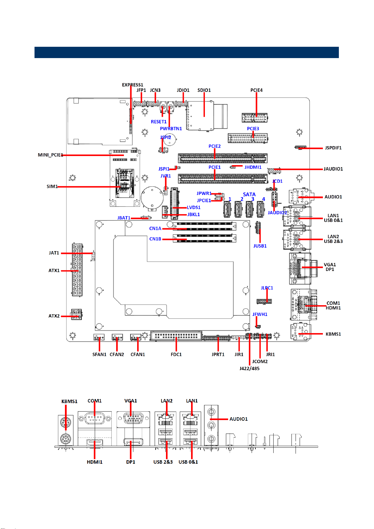
2.1 Product Overview
6 EEV-EX14 Quick Installation Guide
Quick Installation Guide
Jumpers
Label
Function
Note
JAT1
12V control selector
3 x 1 header, pitch 2.54mm
JBAT1
Clear CMOS
3 x 1 header, pitch 2.54mm
JPWR1
S3 signal control selector
3 x 1 header, pitch 2.54mm
JPCIE1
PCIE signal selector
3 x 1 header, pitch 2.54mm
JHDMI1
PCIE2 (DDI) signal selector
2 x 1 header, pitch 2.00mm
JRI1
COM1 pin 9 signal select
3 x 2 header, pitch 2.00mm
2.2 Jumper and Connector List
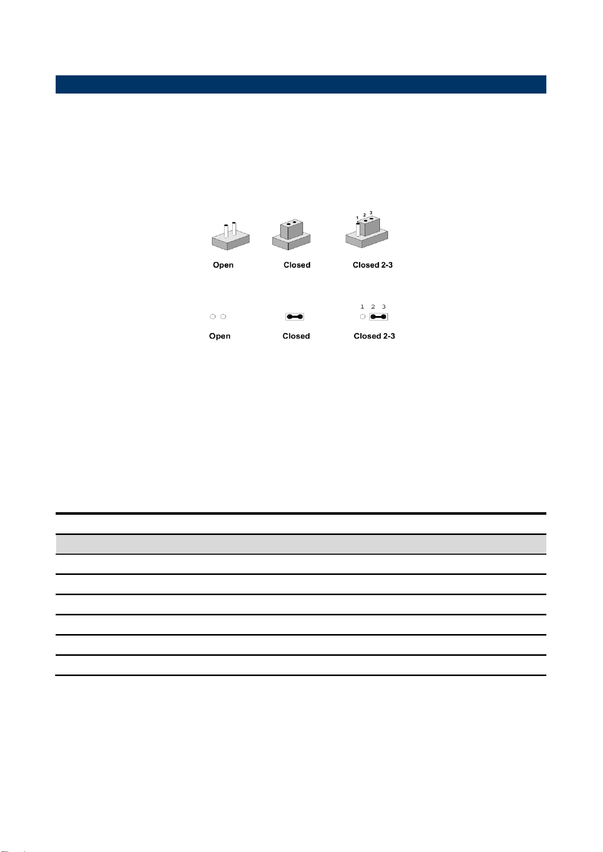
You can configure your board to match the needs of your application by setting jumpers. A
jumper is the simplest kind of electric switch.
It consists of two metal pins and a small metal clip (often protected by a plastic cover) that
slides over the pins to connect them. To “close” a jumper you connect the pins with the clip.
To “open” a jumper you remove the clip. Sometimes a jumper will have three pins, labeled 1,
2, and 3. In this case, you would connect either two pins.
The jumper settings are schematically depicted in this manual as follows:
A pair of needle-nose pliers may be helpful when working with jumpers.
Connectors on the board are linked to external devices such as hard disk drives, a
keyboard, or floppy drives. In addition, the board has a number of jumpers that allow you to
configure your system to suit your application.
If you have any doubts about the best hardware configuration for your application, contact
your local distributor or sales representative before you make any changes.
The following tables list the function of each of the board's jumpers and connectors.
EEV-EX14 Quick Installation Guide 7

EEV-EX14
Connectors
Label
Function
Note
AUDIO1
Audio connector
ATX1
ATX1 Power connector
12 x 2 wafer, pitch 4.2mm
ATX2
ATX2 Power connector
2 x 2 wafer, pitch 4.2mm
COM1
Serial port 1 connector
D-Sub 9 pin
CFAN1
CPU fan connector 1
4 x 1 wafer
CFAN2
CPU fan connector 2
4 x 1 wafer
DP1
Display port connector
EXPRESS1
Express card connector
FDC1
Floppy connector 1
17 x 2 wafer box, pitch 2.54 mm
HDMI1
HDMI connector 1
JAUDIO1
7.1ch Audio connector
6 x 2 header, pitch 2.00mm
JPRT1
Printer connector
13 x 2 header, pitch 2.00mm
JIR1
IR connector
5 x 1 header, pitch 2.00mm
JSPDIF1
SPDIF connector
4 x 1 header, pitch 2.54mm
J422/485
Serial Port 2 RS422/485 connector
3 x 2 header, pitch 2.00mm
JCOM2
Serial Port 2 RS232 connector
5 x 2 header, pitch 2.00mm
KBMS1
KB/MS connector
LAN1/2
Ethernet connector
MINI-PCIE1
PCI Express Mini Card slot
SDIO1
SD card slot
JDIO1
DIO connector
6 x 2 header, pitch 2.00mm
JCN3
MultI-purpose connector
6 x 2 header, pitch 2.00mm
JFP1
Front panel connector
6 x 2 header, pitch 2.00mm
JSPI1
SPI Selector
2 x 1 header, pitch 2.00mm
SIM1
SIM card slot
PWRBTN1
Power button
RESET1
Reset button
SFAN1
System fan connector
4 x 1 wafer
USB 0&1
USB connector 0&1
USB 2&3
USB connector 2&3
VGA1
VGA connector
JSPI2
Carrier board SPI FLASH programming
4 x 2 header, pitch 2.00mm
8 EEV-EX14 Quick Installation Guide

Quick Installation Guide
JVR1
LCD backlight brightness adjustment
connector
3 x 1 header, pitch 2.54mm
PCIE1
PCI Express x16 connector
PCIEXPRESS_164V
PCIE2
Digital Display Interfaces (DDI) slot
PCIEXPRESS_164V
PCIE3
PCI Express x4 connector
PCIEXPRESS_64V
PCIE4
PCI Express x1 connector
PCIEXPRESS_36V
JCD1
CD-ROM Audio Input connector
4 x 1 wafer, pitch 2.54mm
SATA 1/2/3/4
Serial ATA connector
JAUDIO2
Front Audio connector
5 x 2 wafer, pitch 2.54mm
LVDS1
LVDS connector
20 x 2 box header, pitch 1.25
mm
JBKL1
LCD Inverter connector
5 x 1 wafer, pitch 2.00mm
CN1A
COM Express connector A
CN1B
COM Express connector B
JUSB1
USB 4&5 connector
5x 2 header, pitch 2.00mm
JLPC1
LPC port connector
7x 2 header, pitch 2.00mm
JFWH1
Firmware Hub BIOS chip select
2x 1 header, pitch 2.00mm
EEV-EX14 Quick Installation Guide 9
EEV-EX14
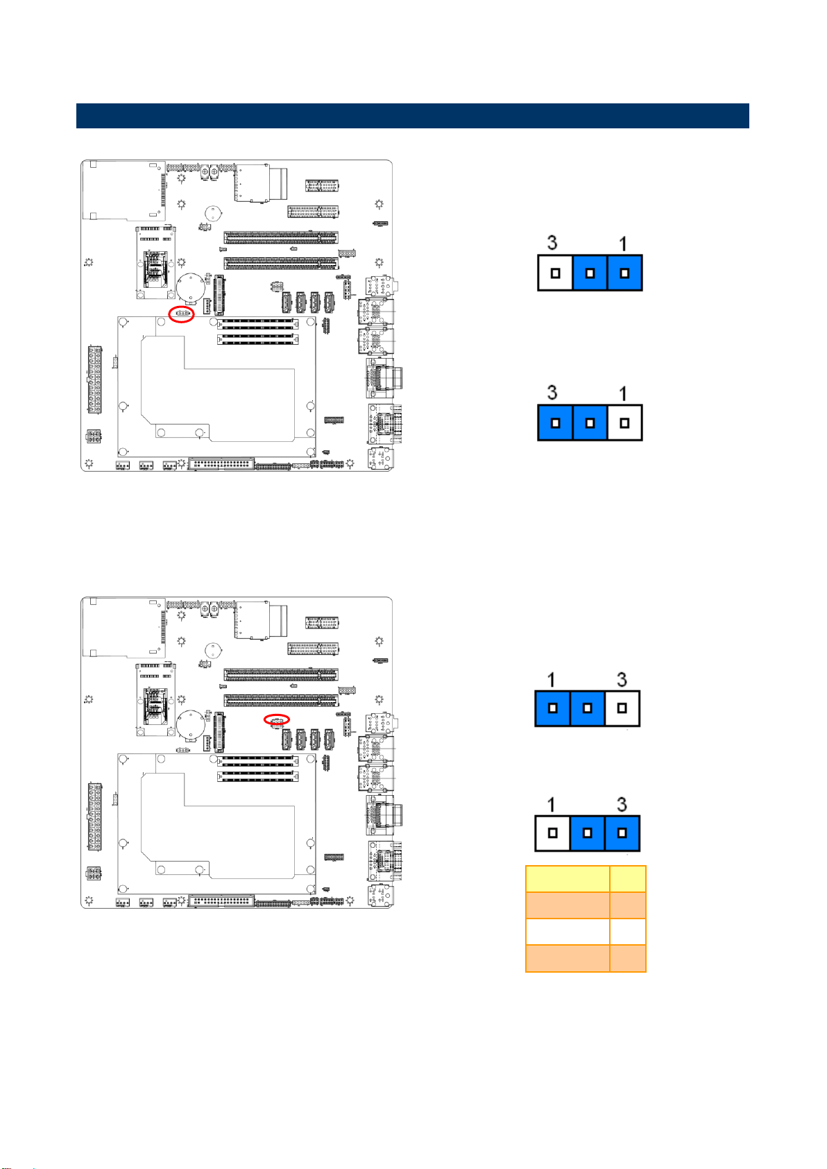
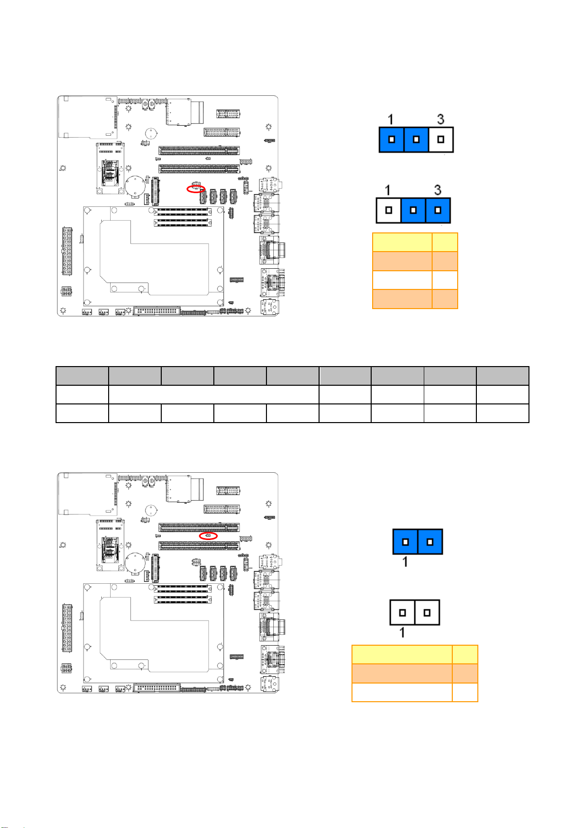
* Default
Protect*
Clear CMOS
* Default
Note:
PIN1(Input):Control by power button
PIN2(Output):Control power IC
PIN3(Input):Module board to Carrier board singal
Control S3
NO Control of S3
Signal
PIN
PWR_S3
1
S3
2
SLP_S3#
3
2.3 Setting Jumpers & Connectors
2.3.1 Clear CMOS (JBAT1)
2.3.2 S3 signal selector (JPWR1)
10 EEV-EX14 Quick Installation Guide
Default*
Signal
PIN
GND
1
SEL
2
+3.3V
3
PCI Express Differential Transmit Pairs
JPCIE1
PCIE [0]
PCIE [1]
PCIE [2]
PCIE [3]
PCIE [4]
PCIE [5]
PCIE [6]
PCIE [7]
SEL=LOW
PCIE3
LAN2
PCIE4
MIIN-PCIE1
EXPRESS1
SEL=HIGH
LAN2
PCIE4
MIIN-PCIE1
EXPRESS1
X X X
X
*Default
HDMI/SDVO*
Display Port
Signal
PIN
+3.3V
1
DDI_DDC_AUX_SEL
2
2.3.3 PCIE signal selector (JPCIE1)
Quick Installation Guide
2.3.4 PCIE2 (DDI) signal selector (JHDMI1)
EEV-EX14 Quick Installation Guide 11
EEV-EX14
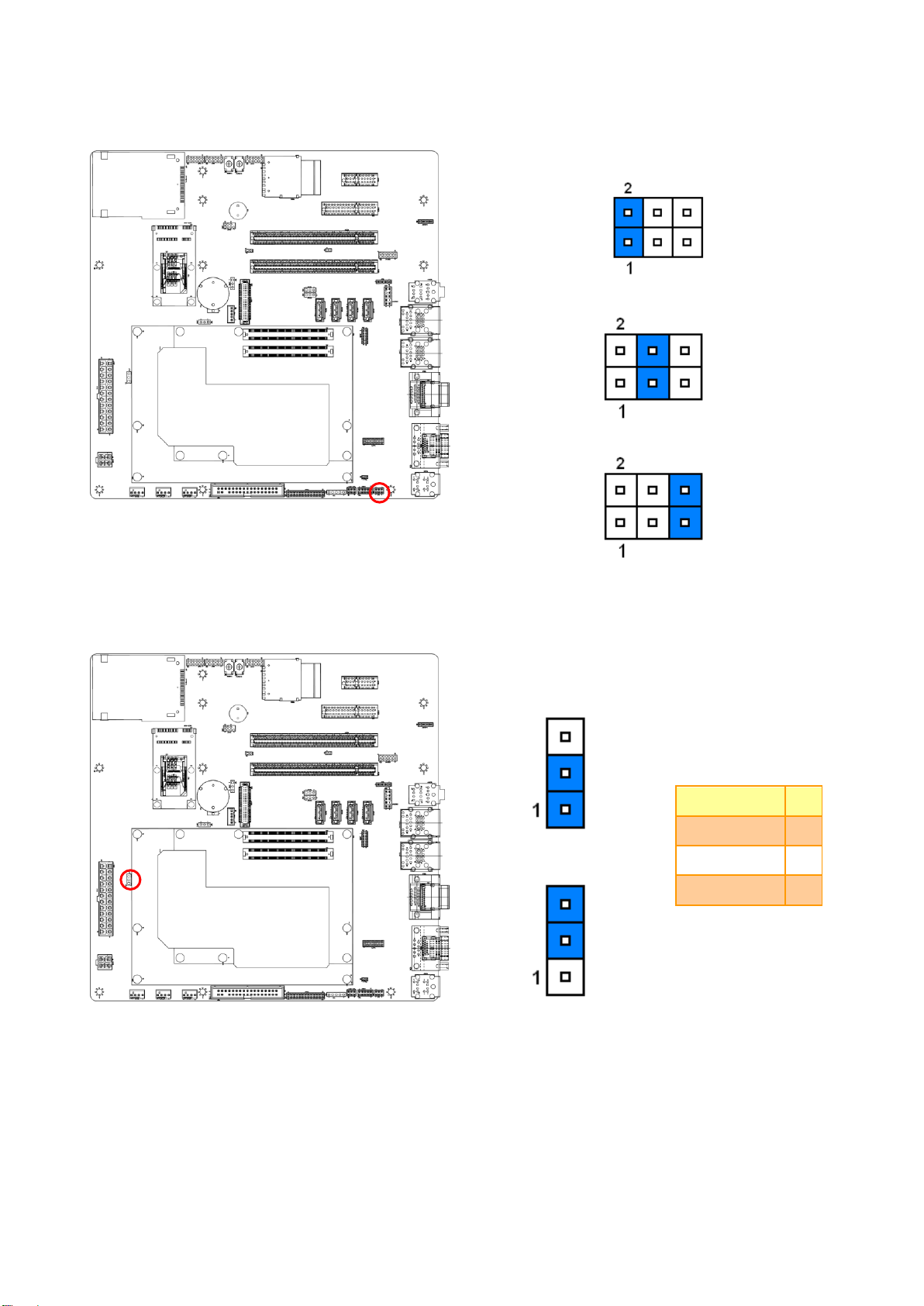
*Default
Ring*
+5V
+12V
*Default
Note:
When jumper 2-3 closed:Module board always have
+12V
12V Control*
12V Always
Signal
PIN
SLP_S3#
1
Enable +12V
2
+3VSB
3
2.3.5 COM1 Pin 9 signal select (JRI1)
2.3.6 AT Power selector (JAT1)
12 EEV-EX14 Quick Installation Guide

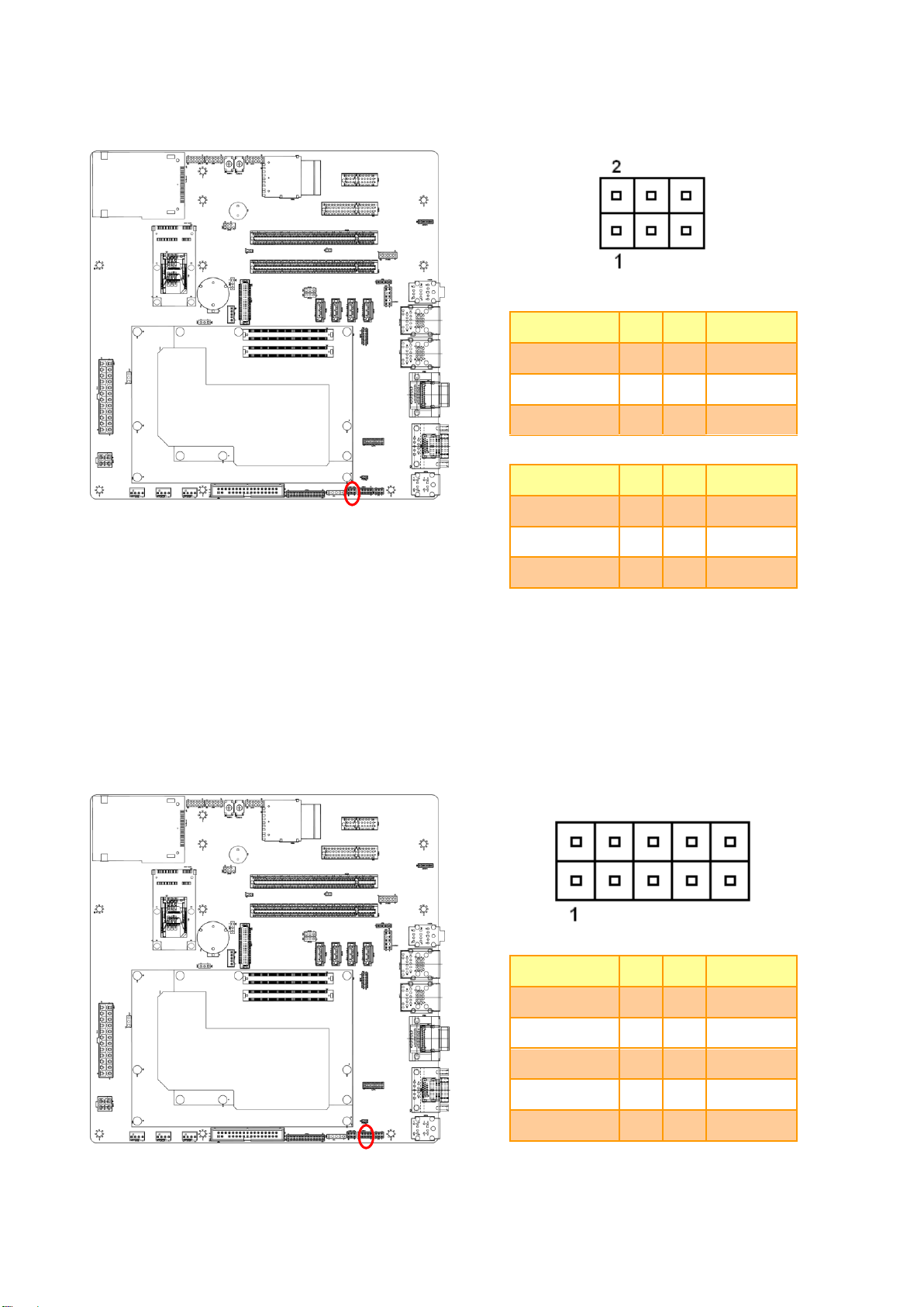
Signal
PIN
PIN
Signal
NC
13 1 NC
NC
14 2 NC
GND
15 3 GND
PSON#
16 4 NC
GND
17 5 GND
GND
18 6 NC
GND
19 7 GND
NC
20 8 NC
NC
21 9 +5VSB
NC
22
10
+12V
NC
23
11
+12V
GND
24
12
NC
Signal
PIN
PIN
Signal
+12V
3 1 GND
+12V
4 2 GND
2.3.7 ATX1 Power connector (ATX1)
Quick Installation Guide
2.3.8 ATX2 Power connector (ATX2)
EEV-EX14 Quick Installation Guide 13

EEV-EX14
CFAN1
Signal
PIN
GND
1
+12V
2
CPUFANIN
3
CPUFANOUT
4
CFAN2
Signal
PIN
GND
1
+12V
2
CPUFANIN1
3
CPUFANOUT1
4
SFAN1
Signal
PIN
GND
1
+12V
2
SYSFANIN
3
SYSFANOUT
4
CFAN1
CFAN2
SFAN1
2.3.9 CPU Fan connector/ System Fan connector 1/ System Fan connector 2
(C_FAN1/ S_FAN1/ S_FAN2)
14 EEV-EX14 Quick Installation Guide

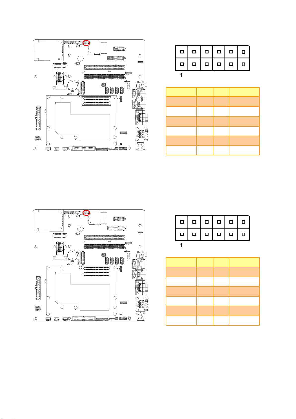
2.3.10 Floppy connector 1 (FDC1)
Signal
PIN
PIN
Signal
GND
1 2 DRVDEN0
GND
3 4 NC
6 NC
GND
7 8 INDEX#
GND
9
10
MOA#
GND
11
12
NC
GND
13
14
DSA#
GND
15
16
NC
GND
17
18
DIR#
GND
19
20
STEP#
GND
21
22
WD#
GND
23
24
WE#
GND
25
26
TRAK0#
GND
27
28
WP#
GND
29
30
RDATA#
GND
31
32
HEAD#
GND
33
34
DSKCHG#
Quick Installation Guide
EEV-EX14 Quick Installation Guide 15

EEV-EX14
Signal
PIN
PIN
Signal
STB-
1 2 LPT_AFD#
PD0
3
4
LPT_ERR#
PD1
5
6
LPT_INIT#
PD2
7
8
LPT_SLIN#
PD3
9
10
GND
PD4
11
12
GND
PD5
13
14
GND
PD6
15
16
GND
PD7
17
18
GND
LPT_ACT#
19
20
GND
LPT_BUSY
21
22
GND
LPT_PE
23
24
GND
LPT_SLCT
25
26
GND
Signal
PIN
+5V
1
NC
2
IRRX
3
GND
4
IRTX
5
2.3.11 Printer connector (JPRT1)
2.3.12 IR Connector (JIR1)
16 EEV-EX14 Quick Installation Guide
422 Mode
Signal
PIN
PIN
Signal
TX-
1 2 RX-
TX+
3
4
RX+
+5V
5
6
GND
485 Mode
Signal
PIN
PIN
Signal
DATA-
1 2 -
DATA+
3
4
-
+5V
5
6
GND
Signal
PIN
PIN
Signal
DCD
1 2 RXDD
TXDD
3
4
DTR
GND
5
6
DSR
RTS
7
8
CTS
RI
9
10
NC
2.3.13 Serial Port 2 RS422/485 connector (J422/485)
Quick Installation Guide
2.3.14 Serial Port 2 RS232 connector (JCOM2)
EEV-EX14 Quick Installation Guide 17
EEV-EX14
Signal
PIN
PIN
Signal
DO0
1 2 DI0
DO1
3 4 DI1
DO2
5 6 DI2
DO3
7 8 DI3
SMB_CLK
9
10
SMB_DAT
GND
11
12
+5V
Signal
PIN
PIN
Signal
SER0_TX
1 2 SER0_RX
SER1_TX
3
4
SER1_RX
SLEEP#
5
6
GND
LID#
7 8 GND
PP_TPM
9
10
GND
PP_TPM
11
12
+3VSB
2.3.15 General Purpose I/O connector (JDIO1)
2.3.16 Multi-purpose connector (JCN3)
18 EEV-EX14 Quick Installation Guide

2.3.17 Front panel connector (JFP1)
Signal
PIN
PIN
Signal
GND
12
11
CASEOPEN#
AT_BN
10
9
EXT_PWRBTN#
SATA_LED#
8
7
+5V
GND
6 5 +5V
GND
4 3 SYS_RERST#
GND
2 1 EXT_PWRBTN#
Pin 1 2 3 4 5 6 7 8 9 10
11
12
Signal
Power Button
Reset
Power LED
HDD LED
Short = AT
Open = ATX
Case Open
Signal
PIN
GND
1
BIOS_DIS1#
2
Note:
jumper 1-2 closed can disable module board SPI
FLASH,use carrier board SPI FLASH
Quick Installation Guide
2.3.18 SPI selector (JSPI1)
EEV-EX14 Quick Installation Guide 19

EEV-EX14
Signal
PIN
PIN
Signal
+3VSB
1 2 GND
SPI_CS#
3 4 SPI_CLK
SPI_MOSI
5
6
SPI_MISO
SPI_HOLD#
7
Signal
PIN
+5V
1
LVDS_BKLT_CTRL
2
GND
3
Variation Resistor
(Recommended: 4.7KΩ, >1/16W)
2.3.19 Carrier board SPI FLASH programming (JSPI2)
2.3.20 LCD backlight brightness adjustment connector (JVR1)
20 EEV-EX14 Quick Installation Guide

2.3.21 LCD Inverter connector (JBKL1)
Signal
PIN
+12V_BKL
1
GND
2
BKLEN
3
LVDS_BKLT_CTRL/PWM
4
+5V
5
Signal
Signal Description
LVDS_BKLT_CTRL
when LVDS_BKLT_CTRL is controlled by carrier board's JVR1,
Vadj = 0.75V ~ 4.25V (Recommended: 4.7KΩ, >1/16W)
BKLEN
LCD backlight ON/OFF control signal
Note:
Quick Installation Guide
For inverter with brightness control function through LVDS_BKLT_CTRL/PWM signal (Pin-4) , it
is possible to control the brightness level by carrier board's JVR1 pin2. In this case, R179 would
be removed to disconnect the PWM control signal from COMExpress module (CN1A Pin-B84).
2.3.21.1 Signal Description – LCD Inverter connector (JBKL1)
EEV-EX14 Quick Installation Guide 21

EEV-EX14
Signal
PIN
PIN
Signal
+5V
2 1 +3.3V
+5V
4 3 +3.3V
LVDS_DDC_SD
6 5 LVDS_DDC_SC
GND
8 7 GND
LVDSA_DATA0
10 9 LVDSA_DATA1
LVDSA_DATA0#
12
11
LVDSA_DATA1#
GND
14
13
GND
LVDSA_DATA2
16
15
LVDSA_DATA3
LVDSA_DATA2#
18
17
LVDSA_DATA3#
GND
20
19
GND
LVDSB_DATA0
22
21
LVDSB_DATA1
LVDSB_DATA0#
24
23
LVDSB_DATA1#
GND
26
25
GND
LVDSB_DATA2
28
27
LVDSB_DATA3
LVDSB_DATA2#
30
29
LVDSB_DATA3#
GND
32
31
GND
LVDSA_CLK
34
33
LVDSB_CLK
LVDSA_CLK#
36
35
LVDSB_CLK#
GND
38
37
GND
+12V
40
39
+12V
Signal
PIN
PIN
Signal
+5V
1 2 GND
D4-
3 4 GND
D4+
5 6 D5+
GND
7 8 D5-
GND
9
10
+5V
2.3.22 LVDS connector (LVDS1)
2.3.23 USB Connector 4 & 5 (JUSB1)
22 EEV-EX14 Quick Installation Guide

Signal
PIN
PIN
Signal
AD0
1 2 +3.3V
AD1
3 4 RESET#
AD2
5 6 FRAME#
AD3
7 8 CLOCK
SERIRQ
9
10
GND
+5V
11
12
GND
+5VSB
13
14
LPC_DRQ1#
Signal
PIN
GND
1
BIOS_DIS0#
2
Note:
jumper 1-2 closed can disable module board
BIOS,use carrier board FWH
2.3.24 LPC port connector (JLPC1)
Quick Installation Guide
2.3.25 Firmware Hub BIOS chip select (JFWH1)
EEV-EX14 Quick Installation Guide 23

EEV-EX14
Signal
PIN
+3.3V
1
S/PDIF-IN
2
S/PDIF-OUT
3
GND
4
Signal
PIN
CD_L
4
GND
3
GND
2
CD_R
1
2.3.26 SPDIF connector (JSPDIF1)
2.3.27 CD-ROM Audio Input connector (JCD1)
24 EEV-EX14 Quick Installation Guide

2.3.28 7.1ch Audio connector (JAUDIO1)
Note:
Pin to pin to the Audio Expansion Card KJAUDIO2
connector
Signal
PIN
PIN
Signal
LFE-OUT
1 2 CEN-OUT
GND
3 4 GND
SURR-R-OUT
5 6 SURR-L-OUT
SIDESURR-R-OUT
7 8 SIDESURR-L-OUT
CEN-JD
9
10
SURR-JD
SIDESURR-JD
11
12
GND
Note:
Pin to pin to the Audio Expansion Card KJAUDIO1
connector
Signal
PIN
PIN
Signal
MIC2-L-IN
1 2 GND
MIC2-R-IN
3 4 ACZ_DET#
LINE2-R-OUT
5 6 MIC2_JD
GND
7
LINE2-L-OUT
9
10
LINE2-JD
Quick Installation Guide
2.3.29 Front Audio connector (JAUDIO2)
EEV-EX14 Quick Installation Guide 25
EEV-EX14
2.4 EEV-EX14 Expansion Boards
2.4.1 Product Overview
ct Overview
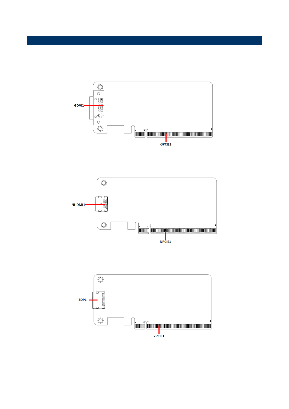
Digital Display Interface Card
HDMI Level Shift Riser Card
Display Port Riser Card
26 EEV-EX14 Quick Installation Guide
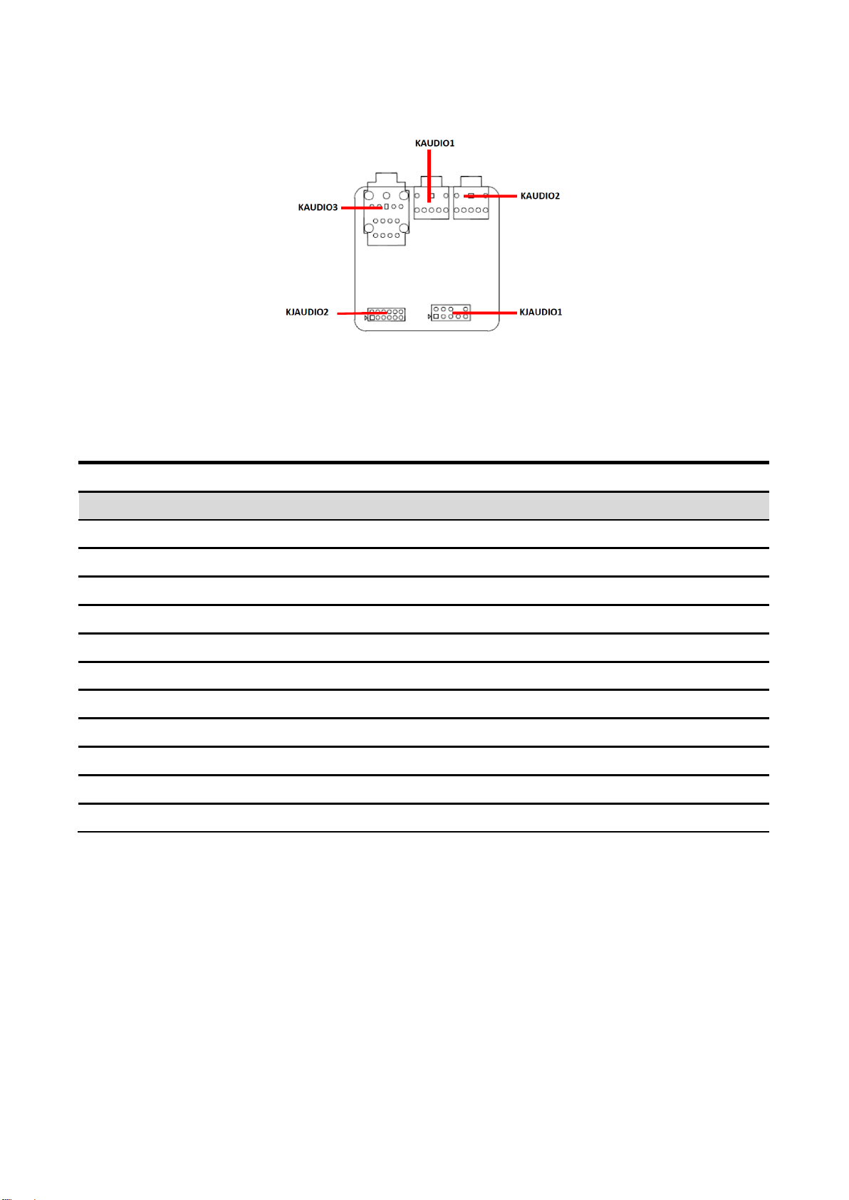
AUDIO Expansion Card(7.1channel & Front audio)
Connectors
Label
Function
Note
GDVI1
DVI connector
GPCIE1
PCIE connector (into the PCIE2)
PCIEXPRESS_164V
NHDMI1
HDMI connector
NPCIE1
PCIE connector(into the PCIE2)
PCIEXPRESS_164V
ZDP1
Display port connector
ZPCIE1
PCIE connector (into the PCIE2)
PCIEXPRESS_164V
KAUDIO1
Audio connector 1
Jack
KAUDIO2
Audio connector 2
Jack
KAUDIO3
Audio connector 3
Jack
KJAUDIO1
Audio Expansion Card for Front Audio
5x 2 header, pitch 2.54mm
KJAUDIO2
Audio Expansion Card for 7.1ch Audio
6x 2 header, pitch 2.00mm
2.4.2 Jumper and Connector List
Quick Installation Guide
EEV-EX14 Quick Installation Guide 27

EEV-EX14
AUDIO Expansion Card
(7.1channel & Front audio)
Signal
PIN
PIN
Signal
MIC2-L-IN
1 2 GND
MIC2-R-IN
3 4 ACZ_DET#
LINE2-R-OUT
5 6 MIC2_JD
GND
7
LINE2-L-OUT
9
10
LINE2-JD
AUDIO Expansion Card
(7.1channel & Front audio)
Signal
PIN
PIN
Signal
LFE-OUT
1 2 CEN-OUT
GND
3 4 GND
SURR-R-OUT
5 6 SURR-L-OUT
SIDESURR-R-OUT
7 8 SIDESURR-L-OUT
CEN-JD
9
10
SURR-JD
SIDESURR-JD
11
12
GND
2.5 EEV-EX14 Expansion Boards Setting
2.5.1 Audio Expansion Card for Front Audio (KJAUDIO1)
2.5.2 Audio Expansion Card for 7.1ch Audio (KJAUDIO2)
28 EEV-EX14 Quick Installation Guide
 Loading...