

Page 1

EEV-EX13
MicroATX COM Express Carrier Board
Quick Installation Guide
1st Ed – 16 July 2009
Part No. E2017EX1300R
Page 2

EEV-EX13
Contents
1. Getting Started............................................................................................................3
1.1 Safety Precautions ................................................................................................3
1.2 Packing List ...........................................................................................................3
2. Hardware Configuration.............................................................................................4
2.1 Product Overview ..................................................................................................5
2.2 Jumper and Connector List....................................................................................6
2.3 Setting Jumpers & Connectors..............................................................................9
2.3.1 COM1/COM2 pin 9 signal select (JP2, JP3) ............................................................................. 9
2.3.2 COM2 RS-232/422/485 Select (JP4) ........................................................................................ 9
2.3.3 COM2 in RS422/485 Mode (JRS422/1) .................................................................................. 10
2.3.4 Clear CMOS (JP5)................................................................................................................... 10
2.3.5 ATX Power Connector (ATX1) ................................................................................................ 11
2.3.6 ATX Power Connector (ATX2) ................................................................................................ 11
2.3.7 SPDIF connector (CN4)........................................................................................................... 12
2.3.8 CD-ROM Audio Input Connector (CN5) .................................................................................. 12
2.3.9 Floppy connector (CN6) .......................................................................................................... 13
2.3.10 CD-ROM Audio Input Connector (JCD1) ................................................................................ 13
2.3.11 LCD Inverter Connector (JBKL1) ............................................................................................ 14
2.3.12 LCD Inverter Connector (JBKL2) ............................................................................................ 14
2.3.13 General Purpose I/O Connector (JDIO1) ................................................................................ 15
2.3.14 Miscellaneous Setting Connector (JFP1) ................................................................................ 15
2.3.15 IrDA Connector (JIR1) ............................................................................................................. 16
2.3.16 LVDS Connector (JLVDS1) ..................................................................................................... 16
2.3.17 TV Out Connector (JTV1)........................................................................................................ 18
2.3.18 USB Connector 7, 4 & 5 (JUSB1, JUSB2) .............................................................................. 19
2.3.19 CPU Fan connector/ System Fan connector 1/ System Fan connector 2 (C_FAN1/ S_FAN1/
S_FAN2) .................................................................................................................................. 19
2 EEV-EX13 Quick Installation Guide
Page 3
Quick Installation Guide
1. Getting Started
1.1 Safety Precautions
Warning!
Always completely disconnect the power cord from your
chassis whenever you work with the hardware. Do not
make connections while the power is on. Sensitive
electronic components can be damaged by sudden power
surges. Only experienced electronics personnel should
open the PC chassis.
Caution!
Always ground yourself to remove any static charge before
touching the CPU card. Modern electronic devices are very
sensitive to static electric charges. As a safety precaution,
use a grounding wrist strap at all times. Place all electronic
components in a static-dissipative surface or static-shielded
bag when they are not in the chassis.
1.2 Packing List
Before you begin installing your single board, please make sure that the
following materials have been shipped:
1 x EEV-EX13 COM Express Evaluation Carrier Board
1 x Quick Installation Guide
1 x CD-ROM or DVD-ROM contains the followings:
— User’s Manual (this manual in PDF file)
— Audio drivers and utilities
EEV-EX13 Quick Installation Guide 3
Page 4
EEV-EX13
2. Hardware
Configuration
4 EEV-EX13 Quick Installation Guide
Page 5
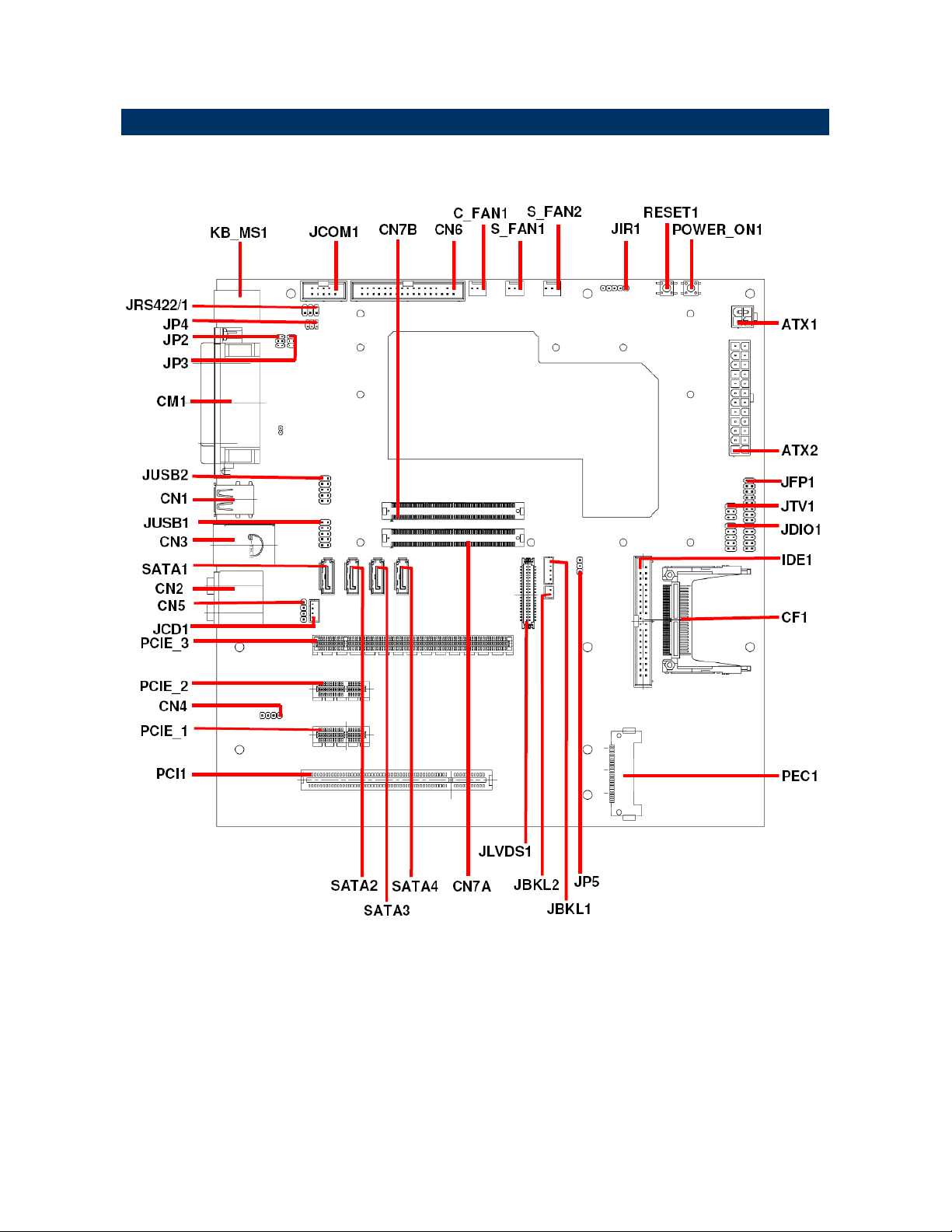
2.1 Product Overview
Quick Installation Guide
EEV-EX13 Quick Installation Guide 5
Page 6
EEV-EX13
2.2 Jumper and Connector List
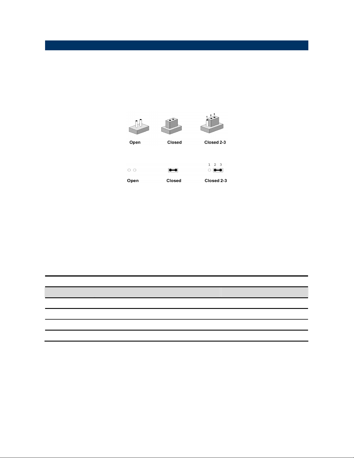
You can configure your board to match the needs of your application by setting jumpers. A
jumper is the simplest kind of electric switch.
It consists of two metal pins and a small metal clip (often protected by a plastic cover) that
slides over the pins to connect them. To “close” a jumper you connect the pins with the clip.
To “open” a jumper you remove the clip. Sometimes a jumper will have three pins, labeled 1,
2, and 3. In this case, you would connect either two pins.
The jumper settings are schematically depicted in this manual as follows:
A pair of needle-nose pliers may be helpful when working with jumpers.
Connectors on the board are linked to external devices such as hard disk drives, a
keyboard, or floppy drives. In addition, the board has a number of jumpers that allow you to
configure your system to suit your application.
If you have any doubts about the best hardware configuration for your application, contact
your local distributor or sales representative before you make any changes.
The following tables list the function of each of the board's jumpers and connectors.
Jumpers
Label Function Note
JP2
JP3
JP4
JP5
6 EEV-EX13 Quick Installation Guide
COM1 pin 9 signal select 3 x 2 header, pitch 2.0mm
COM2 pin 9 signal select 3 x 2 header, pitch 2.0mm
COM2 RS-232/422/485 select 3 x 2 header, pitch 2.0mm
Clear CMOS 3 x 1 header, pitch 2.54mm
Page 7

Quick Installation Guide
Connectors
Label Function Note
ATX1
ATX2
C_FAN1
CF1
CM1-1
CM1-2
CM1-3
CN1
CN2
CN3
CN4
CN5
CN6
CN7A
CN7B
IDE1
ATX Power connector 2 x 2 header
ATX Power connector 12 x 2 header
CPU fan connector 3 x 1 wafer, pitch 2.54mm
Compact Flash card connector
Print port connector D-sub 25-pin, female
Serial Port 1 connector D-sub 9-pin, female
VGA connector D-sub 15-pin, male
USB connector 2&3 Double deck
Audio input connector Phone Jack x 6
USB connector 0&1 Double deck
SPDIF connector 4x 1 header, pitch 2.54mm
CD-ROM audio input connector 4x 1 header, pitch 2.54mm
Floppy connector 17 x 2 header, pitch 2.54mm
ETX Express connector 1
ETX Express connector 2
Primary IDE connector 20 x 2 header, pitch 2.54mm
JBKL1
JBKL2
JCD1
JCOM1
JDIO1
JFP1
JIR1
JLVDS1
JTV1
JRS422/1
JUSB1
JUSB2
KB_MS1
PCI1
PCIE_1
PCIE_2
LCD inverter connector
CD-ROM audio input connector
Serial Port 2 in RS-232 mode
General purpose I/O connector 5 x 2 header, pitch 2.54mm
Miscellaneous setting connector 13 x 2 header, pitch 2.54mm
IrDA connector 5 x 1 header, pitch 2.54mm
LVDS connector DIN-40 PIN, pitch 1.25mm
TV out connector 3 x 2 header, pitch 2.54mm
Serial Port 2 in RS422/485 mode 3 x 2 header, pitch 2.54mm
USB connector 7 5 x 2 header, pitch 2.54mm
USB connector 4&5 5 x 2 header, pitch 2.54mm
PS/2 keyboard & PS/2 mouse connector 6-pin Mini-DIN x 2
PCI slot 1
PCI Express x1 connector
PCI Express x1 connector
5 x 1 wafer, pitch 2.0mm
2 x 1 wafer, pitch 2.0mm
4 x 1 wafer, pitch 2.0mm
5 x 2 header, pitch 2.54mm
PCIE_3
PCI Express x16 connector
EEV-EX13 Quick Installation Guide 7
Page 8

EEV-EX13
Connectors
Label Function Note
PEC1
POWER_ON1
RESET1
S_FAN1
S_FAN2
SATA1
SATA2
SATA3
SATA4
PCI Express card
Power on button
Reset button
System fan connector 1
System fan connector 2
Serial ATA connector 1
Serial ATA connector 2
Serial ATA connector 3
Serial ATA connector 4
3 x 1 wafer, pitch 2.54mm
3 x 1 wafer, pitch 2.54mm
8 EEV-EX13 Quick Installation Guide
Page 9

2.3 Setting Jumpers & Connectors
2.3.1 COM1/COM2 pin 9 signal select (JP2, JP3)
JP2 (COM1)
Ring*
Quick Installation Guide
JP3 (COM2)
Ring*
*
*Default
2.3.2 COM2 RS-232/422/485 Select (JP4)
+5V
+12V
RS-232
+5V
+12V
RS-422
* Default
Note:
Replace JCOM1 by JRS422/1
when the using RS-422/485 mode.
RS-485
EEV-EX13 Quick Installation Guide 9
Page 10

EEV-EX13
2.3.3 COM2 in RS422/485 Mode (JRS422/1)
In 422 Mode
Signal PIN PIN Signal
TX- 1 2 RX-
TX+ 3 4 RX+
+5V 5 6 GND
In 485 Mode
Signal PIN PIN Signal
2.3.4 Clear CMOS (JP5)
* Default
DATA- 1 2 RX-
DATA+ 3 4 RX+
+5V 5 6 GND
Protect*
Clear CMOS
10 EEV-EX13 Quick Installation Guide
Page 11
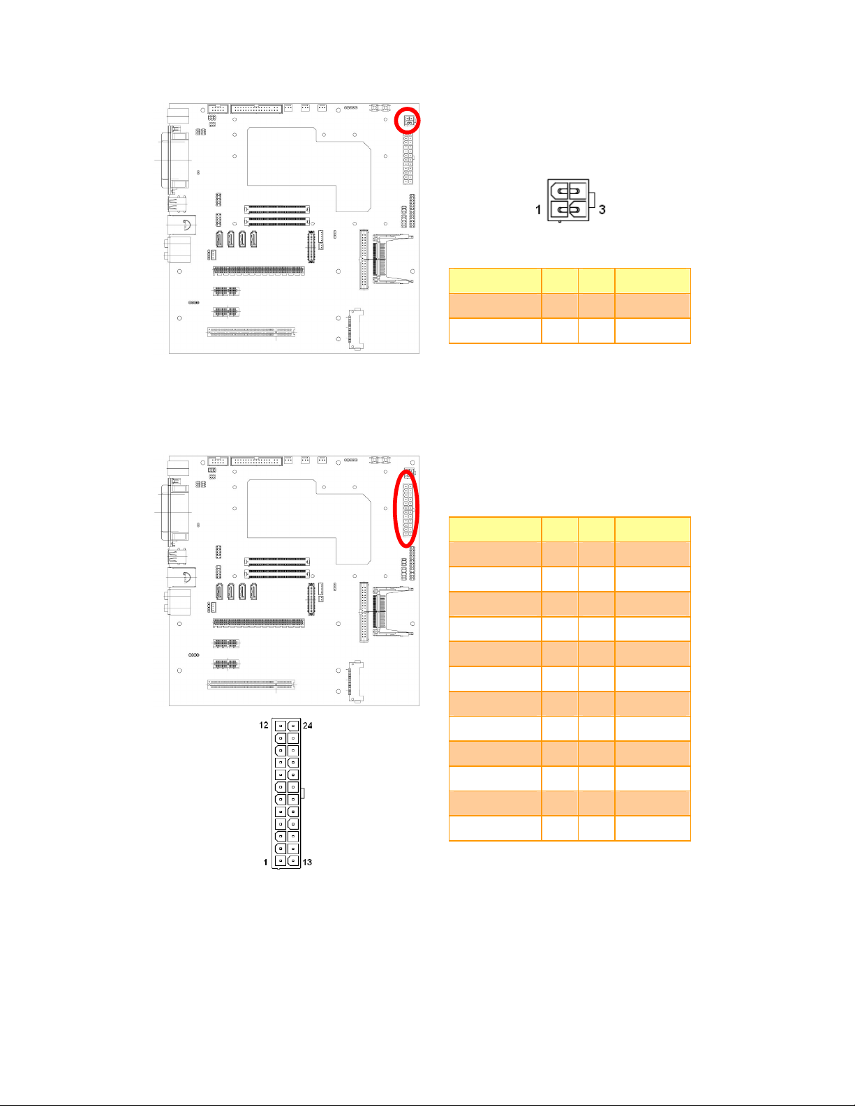
2.3.5 ATX Power Connector (ATX1)
Quick Installation Guide
Signal PIN PIN Signal
GND 2 4 +12V
2.3.6 ATX Power Connector (ATX2)
GND 1 3 +12V
Signal PIN PIN Signal
3.3V 12 24
+12V 11 23
+12V 10 22
AUX5V 9 21
PWROK 8 20
GND 7 19
+5V 6 18
GND 5 17
GND
+5V
+5V
+5V
-5V
GND
GND
GND
+5V 4 16 PS_ON
GND 3 15
3.3V 2 14
3.3V 1 13
GND
-12V
3.3V
EEV-EX13 Quick Installation Guide 11
Page 12

EEV-EX13
2.3.7 SPDIF connector (CN4)
Signal PIN
SPDIFIN 1
GND 2
GND 3
2.3.8 CD-ROM Audio Input Connector (CN5)
SPDIFOUT 4
Signal PIN
CD_R 1
GND 2
GND 3
CD_L 4
12 EEV-EX13 Quick Installation Guide
Page 13

2.3.9 Floppy connector (CN6)
Quick Installation Guide
Signal PIN PIN Signal
GND 1 2 RWC#
GND 3 4 NC
GND 5 6 DRVDEN1
GND 7 8 INDEX#
2.3.10 CD-ROM Audio Input Connector (JCD1)
GND 9 10
GND 11 12
GND 13 14
GND 15 16
GND 17 18
GND 19 20
GND 21 22
GND 23 24
GND 25 26 TRAK0#
GND 27 28
NC 29 30 RDATA#
GND 31 32 HEAD#
NC 33 34 DSKCHG#
MOA#
DSB#
DSA#
MOB#
DIR#
STEP#
WD#
WE#
WP#
Signal PIN
CD_R 4
GND 3
CD_L 2
NC 1
EEV-EX13 Quick Installation Guide 13
Page 14
EEV-EX13
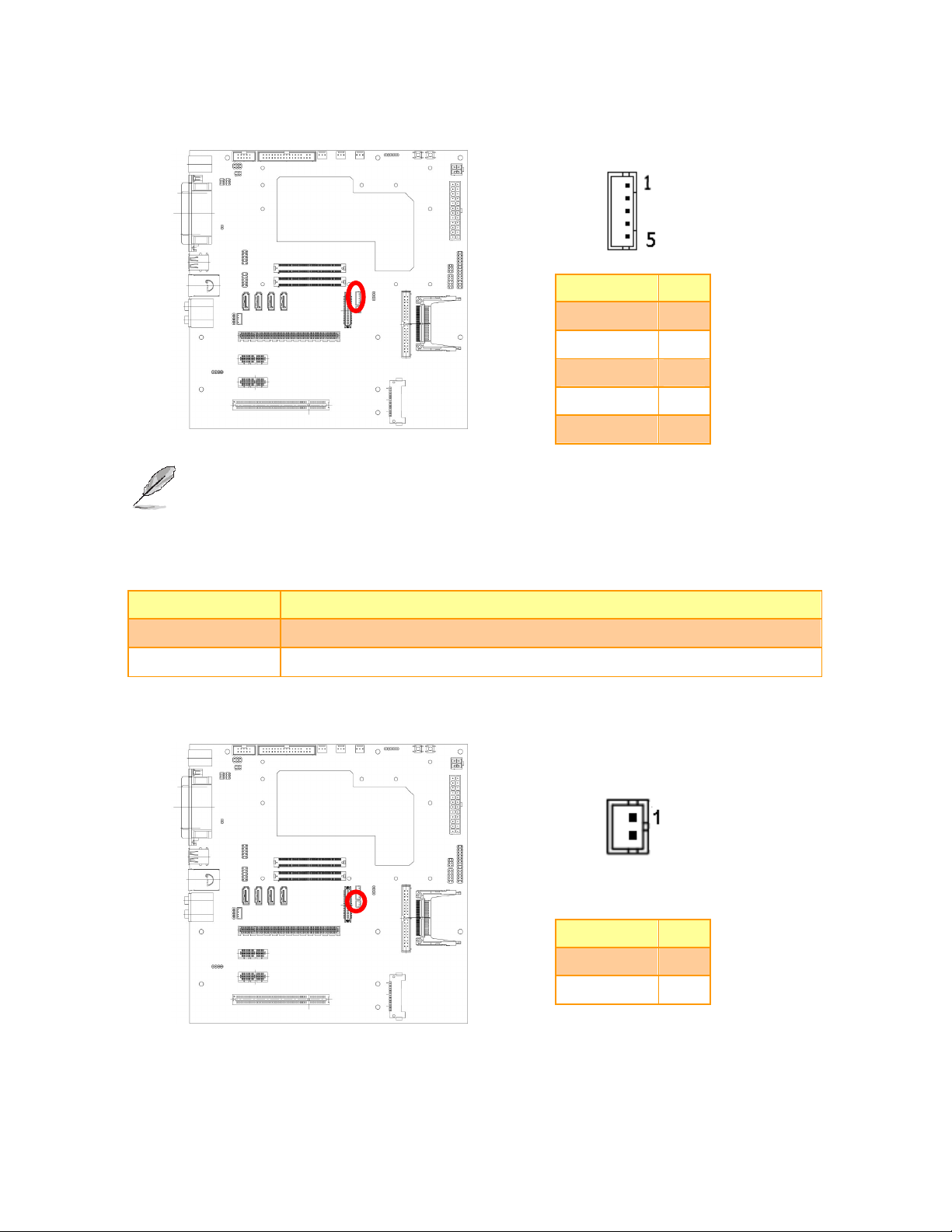
2.3.11 LCD Inverter Connector (JBKL1)
Note:
For inverters with adjustable Backlight function, it is possible to control the LCD
brightness through the VR signal controlled by JFP1. Please see the JFP1
section for detailed circuitry information.
Signal PIN
+12V_BKL 1
GND 2
ENBKL 3
BRIGHT 4
+5V 5
2.3.11.1 Signal Description – LCD Inverter Connector (JBKL1)
Signal Signal Description
BRIGHT Vadj = 0.75V ~ 4.25V (Recommended: 4.7KΩ, >1/16W)
ENBKL LCD backlight ON/OFF control signal
2.3.12 LCD Inverter Connector (JBKL2)
Signal PIN
+12V 1
GND 2
14 EEV-EX13 Quick Installation Guide
Page 15

2.3.13 General Purpose I/O Connector (JDIO1)
Quick Installation Guide
Signal PIN PIN
+5v 1 2 GND
GPO0 3 4 GPI0
GPO1 5 6 GPI1
GPO2 7 8 GPI2
Signal
2.3.14 Miscellaneous Setting Connector (JFP1)
RESET+ 1 2 VCCSB
HDLED- 7 8 GND
VCCSB 9 10 VCCSB
PANSWIN 11 12 SUS_LED-
KB_LOCK- 13 14 +5V
CASEOPEN- 17 18 VTIN3
GPO3 9 10 GPI3
Signal PIN PIN
GND 3 4 GND
+5V 5 6 +5V
GND 15 16 SPKIN
GND 19 20 THRMDN-
Signal
+5V 21 22 +5V
BRIGHT 23 24 MASTER-
GND 25 26 GND
Note: To set the CF Card as
Master , please short JFP1
pin 24 & 26
EEV-EX13 Quick Installation Guide 15
Page 16

EEV-EX13
2.3.15 IrDA Connector (JIR1)
2.3.16 LVDS Connector (JLVDS1)
Signal PIN
+5V 1
NC 2
IRRX 3
GND 4
IRTX 5
Signal PIN PIN
+12V_LVDS 39 40 +12V_LVDS
GND 37 38 GND
LCDDO16 35 36 LCDDO6
LCDDO17 33 34 LCDDO7
GND 31 32 GND
LCDDO18 29 30 LCDDO14
LCDDO19 27 28 LCDDO15
GND 25 26 GND
LCDDO12 23 24 LCDDO10
LCDDO13 21 22 LCDDO11
GND 19 20 GND
LCDDO8 17 18 LCDDO4
LCDDO9 15 16 LCDDO5
GND 13 14 GND
LCDDO2 11 12 LCDDO0
Signal
LCDDO3 9 10 LCDDO1
GND 7 8 GND
I2C_CLK 5 6 I2C_DAT
LVDS_+3.3V 3 4 LVDS_+5V
LVDS_+3.3V 1 2 LVDS_+5V
16 EEV-EX13 Quick Installation Guide
Page 17

Note:
JLVDS1 supports up to dual channel 24-bit LVDS, but the real function depends
on the limitation of the used COM Express module.
2.3.16.1 Signal Description – LVDS Connector (JLVDS1)
Signal 1 Pixel / Clock LVDS Mode 2 Pixel / Clock LVDS Mode
LCDDO0 Txout0# Odd Txout0#
LCDDO1 Txout0 Odd Txout0
LCDDO2 Txout1# Odd Txout1#
LCDDO3 Txout1 Odd Txout1
LCDDO4 Txout2# Odd Txout2#
LCDDO5 Txout2 Odd Txout2
LCDDO6 Txclk# Odd Txclk#
LCDDO7 Txclk Odd Txclk
LCDDO8 Txout3# Odd Txout3#
LCDDO9 Txout3 Odd Txout3
Quick Installation Guide
LCDDO10 - Even Txout0#
LCDDO11 - Even Txout0
LCDDO12 - Even Txout1#
LCDDO13 - Even Txout1
LCDDO14 - Even Txout2#
LCDDO15 - Even Txout2
LCDDO16 - Even Txclk#
LCDDO17 - Even Txclk
LCDDO18 - Even Txout3#
LCDDO19 - Even Txout3
I2C_DAT, I2C_CLK
I2C interface for panel parameter EEPROM. This EERPOM is mounted on the
LVDS receiver. The data in the EEPROM allows the COM Express module to
automatically set the proper timing parameters for a specific LCD panel.
EEV-EX13 Quick Installation Guide 17
Page 18
EEV-EX13
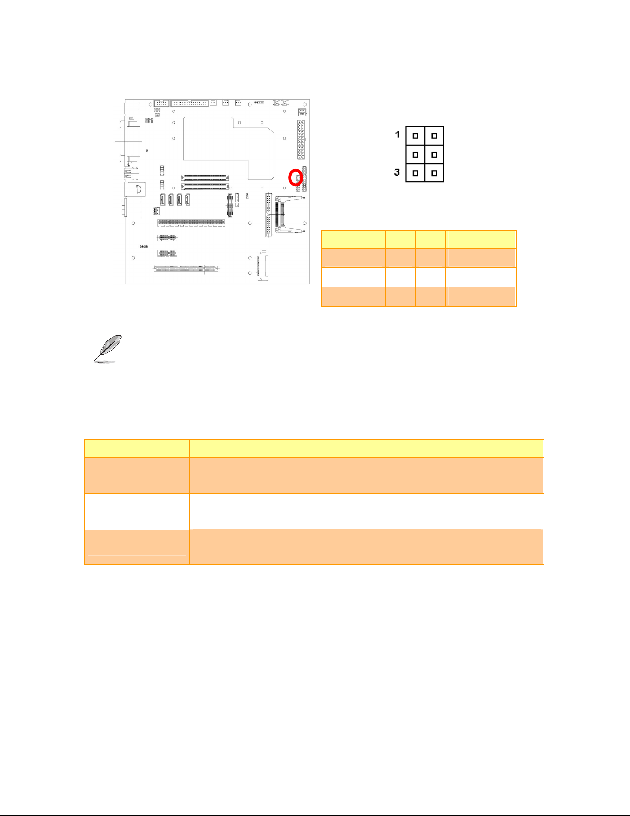
2.3.17 TV Out Connector (JTV1)
Signal PIN PIN
Pb 1 2 GND
Y 3 4 C
GND 5 6 GND
Note:
JTV1 is available when the used COM Express module supports TV out
function.
2.3.17.1 Signal Description – TV Out Connecter (JTV1)
Signal Description
TVDAC Channel A Output: supports CVBS signal of Composite; Chrominance
Pb
(Pb) analog signal of Component.
TVDAC Channel B Output: supports Chrominance analog signal of S-Video;
Pr
Chrominance (Pr) analog signal of Component.
TVDAC Channel C Output: supports Luminance signal of S-Video; Luminance (Y)
Y
analog signal of Component.
Signal
18 EEV-EX13 Quick Installation Guide
Page 19

2.3.18 USB Connector 7, 4 & 5 (JUSB1, JUSB2)
Quick Installation Guide
JUSB1
JUSB2
JUSB2
JUSB1
Signal PIN PIN Signal
+5V 1 2 GND
D6-/D4- 3 4 GND
D6+/D4+ 5 6 D7+/D5+
GND 7 8 D7-/D5-
GND 9 10
+5V
2.3.19 CPU Fan connector/ System Fan connector 1/ System Fan connector 2
(C_FAN1/ S_FAN1/ S_FAN2)
Signal PIN
GND 1
+12V 2
FANIO2/ FANIO3/ FANIO1 3
EEV-EX13 Quick Installation Guide 19
Page 20

EEV-EX13
20 EEV-EX13 Quick Installation Guide
 Loading...