

Page 1

ECM-LX800D
3.5” AMD LX800 Micro Module
Quick Installation Guide
1st Ed – 5 May 2010
Part No. E2017351601R
Page 2

ECM-LX800D
FCC Statement
THIS DEVICE COMPLIES WITH PART 15 FCC RULES. OPERATION IS
SUBJECT TO THE FOLLOWING TWO CONDITIONS:
(1) THIS DEVICE MAY NOT CAUSE HARMFUL INTERFERENCE.
(2) THIS DEVICE MUST ACCEPT ANY INTERFERENCE RECEIVED INCLUDING
INTERFERENCE THAT MAY CAUSE UNDESIRED OPERATION.
THIS EQUIPMENT HAS BEEN TESTED AND FOUND TO COMPLY WITH THE LIMITS
FOR A CLASS "A" DIGITAL DEVICE, PURSUANT TO PART 15 OF THE FCC RULES.
THESE LIMITS ARE DESIGNED TO PROVIDE REASONABLE PROTECTION AGAINST
HARMFUL INTERFERENCE WHEN THE EQUIPMENT IS OPERATED IN A
COMMERCIAL ENVIRONMENT. THIS EQUIPMENT GENERATES, USES, AND CAN
RADIATE RADIO FREQUENCY ENERGY AND, IF NOT INSTALLED AND USED IN
ACCORDANCE WITH THE INSTRUCTION MANUAL, MAY CAUSE HARMFUL
INTERFERENCE TO RADIO COMMUNICATIONS.
OPERATION OF THIS EQUIPMENT IN A RESIDENTIAL AREA IS LIKELY TO CAUSE
HARMFUL INTERFERENCE IN WHICH CASE THE USER WILL BE REQUIRED TO
CORRECT THE INTERFERENCE AT HIS OWN EXPENSE.
Copyright Notice
Copyright © 2010 Avalue Technology Inc., ALL RIGHTS RESERVED.
No part of this document may be reproduced, copied, translated, or transmitted in any form
or by any means, electronic or mechanical, for any purpose, without the prior written
permission of the original manufacturer.
2 ECM-LX800D Quick Installation Guide
Page 3

Quick Installation Guide
Contents
1. Getting Started............................................................................................................4
1.1 Safety Precautions ................................................................................................4
1.2 Packing List ...........................................................................................................4
2. Hardware Configuration.............................................................................................5
2.1 Product Overview ..................................................................................................6
2.2 Jumper and Connector List ...................................................................................7
2.3 Setting Jumpers & Connectors..............................................................................9
2.3.1 AT/ATX select (JAT/ATX) ............................................................................................................ 9
2.3.2 Clear CMOS (JBAT) .................................................................................................................... 9
2.3.3 COM1-Ring, +5V, +12V power select(JRI1) ........................................................................... 10
2.3.4 Touch panel select (JTOUCH_SEL).......................................................................................... 10
2.3.5 Audio Connector (JAUDIO)........................................................................................................11
2.3.6 Power & Power button Connector (PWR& JPWRBTN)............................................................. 11
2.3.7 LCD inverter connector (JBKL).................................................................................................. 12
2.3.8 LCD Backlight Brightness Adjustment Connector (JVR)........................................................... 13
2.3.9 Serial port 2 COM2 in RS-232 Mode (JCOM2) ......................................................................... 13
2.3.10 Serial port 2 in RS-422/485 Mode (JRS422/485).................................................................. 14
2.3.11 General purpose I/O connector (JDIO) ................................................................................. 14
2.3.12 IrDA Connector (JIR) ............................................................................................................. 15
2.3.13 USB Connector 0 & 1 (JUSB)................................................................................................ 15
2.3.14 LVDS Connector (JLVDS) ..................................................................................................... 16
2.3.15 TFT Panel Connector (JTFT) ................................................................................................ 17
2.3.16 Touch Panel Connector (JTOUCH)....................................................................................... 18
2.4 Audio / USB Daughter Board User’s Guide .........................................................19
2.4.1 Jumper and Connector Layout .................................................................................................. 19
2.4.2 Jumper and Connector List........................................................................................................ 19
2.4.3 Setting Jumper and Connector .................................................................................................. 20
ECM-LX800D Series Quick Installation Guide 3
Page 4
ECM-LX800D
1. Getting Started
1.1 Safety Precautions
Warning!
Always completely disconnect the power cord from your
chassis whenever you work with the hardware. Do not
make connections while the power is on. Sensitive
electronic components can be damaged by sudden power
surges. Only experienced electronics personnel should
open the PC chassis.
Caution!
Always ground yourself to remove any static charge before
touching the CPU card. Modern electronic devices are very
sensitive to static electric charges. As a safety precaution,
use a grounding wrist strap at all times. Place all electronic
components in a static-dissipative surface or static-shielded
bag when they are not in the chassis.
1.2 Packing List
Before you begin installing your single board, please make sure that the
following materials have been shipped:
z 1 x ECM-LX800D AMD Geode LX800 Micro Module
z 1 x Quick Installation Guide for ECM-LX800D
z 1 x DVD-ROM contains the followings:
— User’s Manual (this manual in PDF file)
— Ethernet driver and utilities
— VGA drivers and utilities
— Audio drivers and utilities
z 1 x Cable set contains the followings:
— 1 x Daughter board support Audio/2 x USB (P/N:E9697000105R)
— 1 x IDE HDD cable (44-pin, pitch 2.0mm)
— 1 x Audio cable (10pin, 2.0mm pitch)
— 1 x USB cable (10P/2.54mm-10P/2.0mm)
— 1 x PS/2 Keyboard & mouse Y cable (6-pin, Mini-DIN)
4 ECM-LX800D Quick Installation Guide
Page 5

Quick Installation Guide
2. Hardware
Configuration
ECM-LX800D Series Quick Installation Guide 5
Page 6
ECM-LX800D
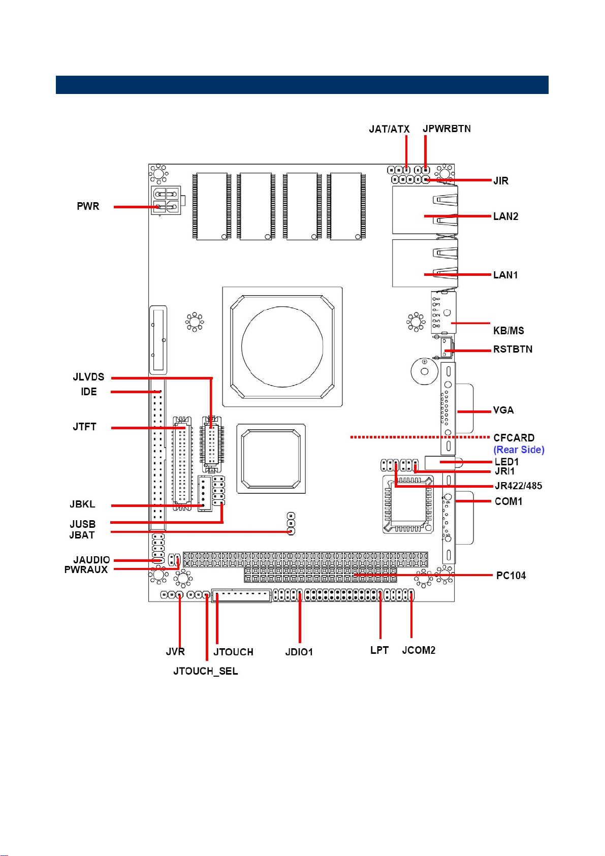
2.1 Product Overview
6 ECM-LX800D Quick Installation Guide
Page 7

Quick Installation Guide
2.2 Jumper and Connector List
You can configure your board to match the needs of your application by setting jumpers. A
jumper is the simplest kind of electric switch.
It consists of two metal pins and a small metal clip (often protected by a plastic cover) that
slides over the pins to connect them. To “close” a jumper you connect the pins with the clip.
To “open” a jumper you remove the clip. Sometimes a jumper will have three pins, labeled 1,
2, and 3. In this case, you would connect either two pins.
The jumper settings are schematically depicted in this manual as follows:
A pair of needle-nose pliers may be helpful when working with jumpers.
Connectors on the board are linked to external devices such as hard disk drives, a
keyboard, or floppy drives. In addition, the board has a number of jumpers that allow you to
configure your system to suit your application.
If you have any doubts about the best hardware configuration for your application, contact
your local distributor or sales representative before you make any changes.
The following tables list the function of each of the board's jumpers and connectors.
Jumpers
Label Function Note
JAT/ATX
JBAT
JRI1
JTOUCH_SEL
AT/ATX select 3 x 1 header, pitch 2.54mm
Clear CMOS 3 x 1 header, pitch 2.54mm
COM1-Ring, +5V, +12V power select
Touch panel select 3 x 1 header, pitch 2.54mm
3 x 2 header, pitch 2.0mm
ECM-LX800D Series Quick Installation Guide 7
Page 8

ECM-LX800D
Connectors
Label Function Note
CFCARD
COM1
IDE
JAUDIO
JBKL
JCOM2
JDIO
JIR
JLVDS
JPWRBTN
JRS422/485
JTFT
JTOUCH
JUSB
JVR
CompactFlash card connector Type I/II x 1
Serial port 1 connector D-sub 9-pin, male
Primary IDE connector 22 x 2 header, pitch 2.0mm
Audio connector 5 x 2 header, pitch 2.0mm
LCD inverter connector 5 x 1 wafer, pitch 2.0mm
Serial port 2 in RS-232 mode connector 5 x 2 header, pitch 2.0mm
General purpose I/O connector 5 x 2 header, pitch 2.0mm
IrDA connector 5 x 1 header, pitch 2.54mm
LVDS connector 10 x 2 header, pitch 1.25mm
Power button connector 2 x 1 header, pitch 2.54mm
Serial port 2 in RS-422/485 mode connector 3 x 2 header, pitch 2.0mm
TFT panel connector HIROSE DF13-40DP-1.25V
Touch panel connector 9 x 1 wafer, pitch 2.0mm
USB connector 0 & 1 5 x 2 header, pitch 2.0mm
LCD backlight brightness adjustment connector 3 x 1 header, pitch 2.54mm
KB/MS
LAN1
LAN2
LED1
LPT
PC-104
PC-104
PWR
PWRAUX
RSTBTN
SODIMM1
VGA
PS/2 keyboard & mouse connector 6-pin Mini-DIN
RJ-45 Ethernet 1
RJ-45 Ethernet 2
Power & HDD indicator
Parallel port connector 13 x 2 header, pitch 2.0mm
PC-104 connector 20 x 2 header, pitch 2.54mm
PC-104 connector 32 x 2 header, pitch 2.54mm
Power connector Wafer box 4P 4.2mm
Auxiliary power connector 2 x 2 header, pitch 2.0mm
Reset button
200-pin DDR SODIMM socket
VGA connector D-sub 15-pin, female
8 ECM-LX800D Quick Installation Guide
Page 9

2.3 Setting Jumpers & Connectors
2.3.1 AT/ATX select (JAT/ATX)
Quick Installation Guide
ATX*
AT
* Default
2.3.2 Clear CMOS (JBAT)
Protect*
Clear CMOS
* Default
ECM-LX800D Series Quick Installation Guide 9
Page 10

ECM-LX800D
2.3.3 COM1-Ring, +5V, +12V power select(JRI1)
Ring*
+5V
+12V
* Default
2.3.4 Touch panel select (JTOUCH_SEL)
4 WIRE / 8 WIRE
5 WIRE*
* Default
10 ECM-LX800D Quick Installation Guide
Page 11

2.3.5 Audio Connector (JAUDIO)
Quick Installation Guide
Signal PIN PIN Signal
NC 10 9 NC
MIC-REF 8 7 MIC-IN
LIN_L 6 5 LIN_R
GND 4 3 GND
LINEOUT _L 2 1 LINEOUT _R
2.3.6 Power & Power button Connector (PWR& JPWRBTN)
JPWRBTN
Signal PIN PIN Signal
GND 2 4 VIN
GND 1 3 VIN
JPWRBTN
PIN Signal
1 PWRBTN
2 GND
ECM-LX800D Series Quick Installation Guide 11
Page 12

ECM-LX800D
2.3.7 LCD inverter connector (JBKL)
Signal PIN
+5V 5
VR 4
ENBKL 3
GND 2
VIN 1
Note: The power input voltage (VIN)
equals to output voltage of inverter.
Note:
For inverters with adjustable Backlight function, it is possible to control the
LCD brightness through the VR signal controlled by JVR. Please see the
JVR section for detailed circuitry information.
2.3.7.1 Signal Description – LCD Inverter Connector (JBKL)
Signal Signal Description
VR Vadj = 0.75V ~ 4.25V (Recommended: 4.7KΩ, >1/16W)
ENBKL LCD backlight ON/OFF control signal
12 ECM-LX800D Quick Installation Guide
Page 13

Quick Installation Guide
2.3.8 LCD Backlight Brightness Adjustment Connector (JVR)
PIN Signal
1 GND
2 VR
3 +5V
2.3.9 Serial port 2 COM2 in RS-232 Mode (JCOM2)
Signal PIN PIN Signal
NC 10 9 RI
CTS 8 7 RTS
DSR 6 5 GND
DTR 4 3 TxD
RxD 2 1 DCD
ECM-LX800D Series Quick Installation Guide 13
Page 14

ECM-LX800D
2.3.10 Serial port 2 in RS-422/485 Mode (JRS422/485)
Signal PIN PIN Signal
+5V 5 6 GND
TxD+ 3 4 RxD-
TxD- 1 2 RxD+
Note:
JRS422/485 is available after modifying the
mode of COM2 in BIOS setting.
2.3.11 General purpose I/O connector (JDIO)
Signal PIN PIN Signal
DI0 1 2 DO0
14 ECM-LX800D Quick Installation Guide
DI1 3 4 DO1
DI2 5 6 DO2
DI3 7 8 DO3
+5V 9 10 GND
Page 15

2.3.12 IrDA Connector (JIR)
Quick Installation Guide
Signal PIN
+5V 1
NC 2
IRRX 3
GND 4
IRTX 5
2.3.13 USB Connector 0 & 1 (JUSB)
Signal PIN PIN Signal
+5V 10 9 GND
D1- 8 7 GND
D1+ 6 5 D0+
GND 4 3 D0-
GND 2 1 +5V
ECM-LX800D Series Quick Installation Guide 15
Page 16

ECM-LX800D
2.3.14 LVDS Connector (JLVDS)
18-bit
Signal PIN PIN Signal
+3.3V 19 20 +5V
+3.3V 17 18 +5V
I2C_DAT 15 16 I2C_CLK
GND 13 14 GND
Txclk 11 12 Txclk#
NC 9 10 NC
Txout2 7 8 Txout2#
Txout1 5 6 Txout1#
Txout0 3 4 Txout0#
GND 1 2 GND
24-bit (Optional)
Signal PIN PIN Signal
+3.3V 19 20 +5V
+3.3V 17 18 +5V
I2C_DAT 15 16 I2C_CLK
GND 13 14 GND
Txclk 11 12 Txclk#
Txout3 9 10 Txout3#
Txout2 7 8 Txout2#
Txout1 5 6 Txout1#
Txout0 3 4 Txout0#
GND 1 2 GND
2.3.14.1 Signal Description – LVDS Connector (JLVDS)
Signal Description
I2C interface for panel parameter EEPROM. This EERPOM is mounted on the
I2C_DAT, I2C_CLK
LVDS receiver. The data in the EEPROM allows the EXT module to automatically
set the proper timing parameters for a specific LCD panel.
16 ECM-LX800D Quick Installation Guide
Page 17

2.3.15 TFT Panel Connector (JTFT)
Quick Installation Guide
Signal PIN PIN Signal
ENBKL 39 40 NC
LDEMOD 37 38 HSYNC
SHCLK 35 36 VSYNC
GND 33 34 GND
P22 31 32 P23
P20 29 30 P21
P18 27 28 P19
P16 25 26 P17
P14 23 24 P15
P12 21 22 P13
P10 19 20 P11
P8 17 18 P9
P6 15 16 P7
P4 13 14 P5
P2 11 12 P3
P0 9 10 P1
NC 7 8 GND
+3.3V 5 6 +3.3V
GND 3 4 GND
+5V 1 2 +5V
2.3.15.1 Signal Description – TFT Panel Connector (JTFT)
Signal Description
B [0:6]G[0:6]R[0:6] Flat panel data output for 24 bit TFT flat panels. The flat panel data and control
outputs are all on-board controlled for secure power-on/off sequencing
SHCLK Shift Clock. Pixel clock for flat panel data
HSYNC Flat panel equivalent of horizontal synchronization
VSYNC Flat panel equivalent of vertical synchronization
LDEMOD Multipurpose signal, function depends on panel type. May be used as AC drive
control signal or as BLANK# or Display Enable signal
ENBKL Enable backlight signal. This signal is controlled as a part of the panel power
sequencing
ECM-LX800D Series Quick Installation Guide 17
Page 18

ECM-LX800D
2.3.15.2 Signal Description – TFT Panel Display (JTFT)
Signal 18-bit TFT 24-bit TFT
P0 - B0
P1 - B1
P2 B0 B2
P3 B1 B3
P4 B2 B4
P5 B3 B5
P6 B4 B6
P7 B5 B7
P8 - G0
P9 - G1
P10 G0 G2
P11 G1 G3
P12 G2 G4
P13 G3 G5
P14 G4 G6
P15 G5 G7
P16 - R0
P17 - R1
P18 R0 R2
P19 R1 R3
P20 R2 R4
P21 R3 R5
P22 R4 R6
P23 R5 R7
2.3.16 Touch Panel Connector (JTOUCH)
PIN 4-Wire 5-Wire 8-Wire
1 NA NA Right Sense
2 NA NA Left Sense
3 NA NA Bottom Sense
4 NA Sense Top Sense
5 Right LR Right Excite
6 Left LL Left Excite
7 Bottom UR Bottom Excite
8 Top UL Top Excite
9 GND GND GND
18 ECM-LX800D Quick Installation Guide
Page 19

2.4 Audio / USB Daughter Board User’s Guide
2.4.1 Jumper and Connector Layout
Quick Installation Guide
2.4.2 Jumper and Connector List
Jumpers
Label Function Note
JP6
Line out / Speaker out select (The speaker
out function is only available in combine
used of main board)
1-3, 2-4 Speaker out
3-5, 4-6 Line out (Default)
Connectors
Label Function Note
CN1, CN2
CN3
CN4
CN5
CN6
USB 1.1/2.0 connector
TV out connector (Optional) RCA connector
Line out connector Phone Jack
Line in connector Phone Jack
Mic in connector Phone Jack
JP1
JP2
JP3
JP4
JP5
JP7
2.54mm USB 1.1/2.0 connector 1
2.0mm Connector for S-Video (Optional)
Audio connector
2.54mm USB 1.1/2.0 connector 2
2.0mm USB 1.1/2.0 connector
TV / Audio connector 8 x 2 header, pitch 2.54mm
ECM-LX800D Series Quick Installation Guide 19
5 x 2 header, pitch 2.54mm
3 x 2 header, pitch 2.0mm
5 x 2 header, pitch 2.0mm
5 x 2 header, pitch 2.54mm
5 x 2 header, pitch 2.0mm
Page 20

ECM-LX800D
2.4.3 Setting Jumper and Connector
Line out / Speaker out Select (JP6) 2.54mm USB 1.1/2.0 Connector 1 (JP1)
Line Out*
Signal PIN PIN Signal
+5V 1 2 GND
D1- 3 4 GND
D1+ 5 6 D2+
GND 7 8 D2-
GND 9 10 +5V
Speaker Out
Note: Wrong USB cable
configuration with your
USB devices might cause
your USB devices
damaged.
2.0mm Connector for S-Video Signal (JP2) Audio Connector (JP3)
Signal PIN PIN Signal
GND 1 2 GND
Cout 3 4 Yout
GND 5 6 GND
2.54mm USB 1.1/2.0
Connector 2 (JP4)
Signal PIN PIN Signal
+5V 1 2 +5V
D1- 3 4 D2-
D1+ 5 6 D2+
GND 7 8 GND
NC 9 10 NC
Signal PIN PIN Signal
Line out R 1 2 Line out L
GND 3 4 GND
Line in R 5 6 Line in L
Mic In 7 8 Mic Bais
SPK R 9 10 SPK L
2.0mm USB 1.1/2.0
Connector (JP5)
Signal PIN PIN Signal
+5V 1 2 GND
D1- 3 4 GND
D1+ 5 6 D2+
GND 7 8 D2-
GND 9 10 +5V
TV / Audio Connector
(JP7)
Signal PIN PIN Signal
Mic In 1 2 Mic Bais
GND 3 4 GND
Line out L 5 6 Line out R
SPK L 7 8 SPK R
Line in L 9 10 Line in R
GND 11 12 Yout
20 ECM-LX800D Quick Installation Guide
TVGND 13 14 Cout
TVGND 15 16 COMP
 Loading...