


EBM-CDV
5.25” Intel Cedarview Atom Mini Module
User’s Manual
4th Ed – 09 July 2014
Part No. E2047582003R

EBM-CDV User’s Manual
FCC Statement
A Message to the Customer
THIS DEVICE COMPLIES WITH PART 15 FCC RULES. OPERATION IS
SUBJECT TO THE FOLLOWING TWO CONDITIONS:
(1) THIS DEVICE MAY NOT CAUSE HARMFUL INTERFERENCE.
(2) THIS DEVICE MUST ACCEPT ANY INTERFERENCE RECEIVED INCLUDING
INTERFERENCE THAT MAY CAUSE UNDESIRED OPERATION.
THIS EQUIPMENT HAS BEEN TESTED AND FOUND TO COMPLY WITH THE LIMITS
FOR A CLASS "A" DIGITAL DEVICE, PURSUANT TO PART 15 OF THE FCC RULES.
THESE LIMITS ARE DESIGNED TO PROVIDE REASONABLE PROTECTION AGAINST
HARMFUL INTERFERENCE WHEN THE EQUIPMENT IS OPERATED IN A
COMMERCIAL ENVIRONMENT. THIS EQUIPMENT GENERATES, USES, AND CAN
RADIATE RADIO FREQUENCY ENERGY AND, IF NOT INSTATLLED AND USED IN
ACCORDANCE WITH THE INSTRUCTION MANUAL, MAY CAUSE HARMFUL
INTERFERENCE TO RADIO COMMUNICATIONS.
OPERATION OF THIS EQUIPMENT IN A RESIDENTIAL AREA IS LIKELY TO CAUSE
HARMFUL INTERFERENCE IN WHICH CASE THE USER WILL BE REQUIRED TO
CORRECT THE INTERFERENCE AT HIS OWN EXPENSE.
Avalue Customer Services
Each and every Avalue’s product is built to the most exacting specifications to ensure
reliable performance in the harsh and demanding conditions typical of industrial
environments. Whether your new Avalue device is destined for the laboratory or the factory
floor, you can be assured that your product will provide the reliability and ease of operation
for which the name Avalue has come to be known.
Your satisfaction is our primary concern. Here is a guide to Avalue’s customer services. To
ensure you get the full benefit of our services, please follow the instructions below carefully.
Technical Support
We want you to get the maximum performance from your products. So if you run into
technical difficulties, we are here to help. For the most frequently asked questions, you can
easily find answers in your product documentation. These answers are normally a lot more
detailed than the ones we can give over the phone. So please consult the user’s manual
first.
To receive the latest version of the user’s manual; please visit our Web site at:
http://www.avalue.com.tw/
2 EBM-CDV User’s Manual

User’s Manual
3
Content
1. Getting Started ............................................................................................................ 6
1.1 Safety Precautions .................................................................................................... 6
1.2 Packing List ............................................................................................................... 6
1.3 Document Amendment History ................................................................................. 7
1.4 Manual Objectives ..................................................................................................... 8
1.5 System Specifications ............................................................................................... 9
1.6 Architecture Overview—Block Diagram .................................................................. 12
2. Hardware Configuration ........................................................................................... 13
2.1 Product Overview .................................................................................................... 14
2.2 Jumper and Connector List ..................................................................................... 15
2.3 Setting Jumpers & Connectors ............................................................................... 18
2.3.1 Clear CMOS (JBAT1) ..................................................................................................................... 18
2.3.2 Serial port 1/ 2 RS-232/ 422/ 485 mode select (JP1/ JP2) ............................................................ 18
2.3.3 SATA Power select (JP3) ............................................................................................................... 19
2.3.4 Serial port 1/ 2 – RS232/ 422/ 485 mode select (SW1) ................................................................. 19
2.3.5 Multi-function select (SW2) ............................................................................................................ 20
2.3.6 Serial port 1/ 2 pin9 signal select (JRI1/ JRI2) ............................................................................... 20
2.3.7 LCD backlight brightness adjustment (JVR1) ................................................................................ 21
2.3.8 Handset Speaker Out selector (JHS1) ........................................................................................... 22
2.3.9 USB Power select (USB_PWR_SEL1) .......................................................................................... 22
2.3.10 Power connector (PWR2) .......................................................................................................... 23
2.3.11 DVI connector (DVI1) ................................................................................................................. 23
2.3.12 LCD Inverter connector (JBKL1) ................................................................................................ 24
2.3.13 LCD Inverter connector (JBKL2) ................................................................................................ 25
2.3.14 CPU fan connector (CPU_FAN1) .............................................................................................. 25
2.3.15 Serial port 2 connector (COM2) ................................................................................................. 26
2.3.16 Serial port 3/ 4/ 5/ 6 connector (COM3/ COM4/ COM5/ COM6) ............................................... 26
2.3.17 LED indicator connector (JLED1) .............................................................................................. 27
2.3.18 General purpose I/O connector (DIO1) ...................................................................................... 28
2.3.19 LVDS connector (JLVDS1) ........................................................................................................ 29
2.3.20 LVDS connector (JLVDS2) ........................................................................................................ 30
2.3.21 Touch panel connector (JTOUCH) ............................................................................................ 31
2.3.22 USB connector 5&6 (USB56)..................................................................................................... 31
2.3.23 USB connector 7&8 (USB78)..................................................................................................... 32
2.3.24 Battery connector (BT1) ............................................................................................................. 32
2.3.25 Audio connector (AUD1) ............................................................................................................ 33
2.3.26 AMPLIFIER_R1 (AMP_R1) ........................................................................................................ 33
EBM-CDV User’s Manual

EBM-CDV User’s Manual
2.3.27 AMPLIFIER_L1 (AMP_L1) ......................................................................................................... 34
2.3.28 VGA connector (JVGA1) ............................................................................................................ 34
2.3.29 LPC connector (JLPC1) ............................................................................................................. 35
2.3.30 SPI connector (JSPI1) ............................................................................................................... 35
2.3.31 EC_Program (EC_SPI1) ............................................................................................................ 36
2.3.32 SATA Power connector 1 (SPWR1) .......................................................................................... 36
3.BIOS Setup .................................................................................................................... 37
3.1 Introduction ............................................................................................................. 38
3.2 Starting Setup ......................................................................................................... 38
3.3 Using Setup ............................................................................................................ 39
3.4 Getting Help ............................................................................................................ 40
3.5 In Case of Problems ................................................................................................ 40
3.6 BIOS setup ................................................................ ................................ .............. 41
3.6.1 Main Menu ...................................................................................................................................... 41
3.6.1.1 System Language .................................................................................................................. 41
3.6.1.2 System Date .......................................................................................................................... 41
3.6.1.3 System Time .......................................................................................................................... 41
3.6.2 Advanced BIOS settings ................................................................................................................ 42
3.6.2.1 PCI Subsystem Settings ........................................................................................................ 42
3.6.2.2 ACPI Settings ........................................................................................................................ 43
3.6.2.3 S5 RTC Wake settings .......................................................................................................... 44
3.6.2.4 CPU Configuration ................................................................................................................. 45
3.6.2.5 Thermal Configuration ........................................................................................................... 46
3.6.2.6 IDE Configuration .................................................................................................................. 48
3.6.2.7 Intel Fast Flash Standby ........................................................................................................ 49
3.6.2.8 USB Configuration ................................................................................................................. 49
3.6.2.9 H/W Monitor .......................................................................................................................... 50
3.6.2.10 Smart settings ........................................................................................................................ 51
3.6.2.11 Second Super IO Configuration ............................................................................................. 52
3.6.2.12 Super IO Configuration .......................................................................................................... 56
3.6.2.13 PPM configuration ................................................................................................................. 59
3.6.3 Advanced Chipset Features ........................................................................................................... 60
3.6.3.1 Host bridge ............................................................................................................................ 60
3.6.3.2 South bridge .......................................................................................................................... 64
3.6.4 Boot settings ................................................................................................................................... 69
3.6.5 Security........................................................................................................................................... 70
3.6.5.1 Administrator Password ......................................................................................................... 70
3.6.5.2 User Password ...................................................................................................................... 70
3.6.6 Save & Exit ..................................................................................................................................... 71
3.6.6.1 Save Changes and Exit ......................................................................................................... 71
4 EBM-CDV User’s Manual

User’s Manual
5
3.6.6.2 Discard Changes and Exit ..................................................................................................... 71
3.6.6.3 Save Changes and Reset ...................................................................................................... 72
3.6.6.4 Discard Changes and Reset .................................................................................................. 72
3.6.6.5 Save Changes ....................................................................................................................... 72
3.6.6.6 Discard Changes ................................................................................................................... 72
3.6.6.7 Restore Defaults .................................................................................................................... 72
3.6.6.8 Save as user defaults ............................................................................................................ 72
3.6.6.9 Restore user defaults ............................................................................................................ 72
3.6.6.10 Boot override ......................................................................................................................... 72
4. Drivers Installation....................................................................................................... 73
4.1 Install VGA Driver .................................................................................................... 74
4.2 Install Chipset Driver (Cedarview) ........................................................................... 76
4.3 Install Audio Driver (For Realtek ALC892) .............................................................. 77
4.4 Install Ethernet Driver (For Realtek 82574L) ........................................................... 78
5. Mechanical Drawing .................................................................................................... 80
EBM-CDV User’s Manual
EBM-CDV User’s Manual
1. Getting Started
1.1 Safety Precautions
Warning!
Always completely disconnect the power cord from your
chassis whenever you work with the hardware. Do not
make connections while the power is on. Sensitive
electronic components can be damaged by sudden power
surges. Only experienced electronics personnel should
open the PC chassis.
Caution!
Always ground yourself to remove any static charge before
touching the CPU card. Modern electronic devices are very
sensitive to static electric charges. As a safety precaution,
use a grounding wrist strap at all times. Place all electronic
components in a static-dissipative surface or static-shielded
bag when they are not in the chassis.
1.2 Packing List
Before you begin installing your single board, please make sure that the
following materials have been shipped:
1 x EBM-CDV 5.25” Intel Cedarview Atom Mini Module
1 x Quick Installation Guide for EBM-CDV
1 x DVD-ROM or CD-ROM contains the followings:
— User’s Manual (this manual in PDF file)
— Ethernet driver and utilities
— VGA drivers and utilities
— Audio drivers and utilities
6 EBM-CDV User’s Manual

User’s Manual
7
Revision
Date
By
Comment
1st
June 2012
Avalue
Initial Release
2nd
November
2012
Avalue
Pin Signal Update
3rd
March 2013
Avalue
Specifications Update
4th
July 2014
Avalue
Block Diagram Update
1.3 Document Amendment History
EBM-CDV User’s Manual

EBM-CDV User’s Manual
1.4 Manual Objectives
This manual describes in details Avalue Technology EBM-CDV Single Board.
We have tried to include as much information as possible but we have not duplicated
information that is provided in the standard IBM Technical References, unless it proved to
be necessary to aid in the understanding of this board.
We strongly recommend that you study this manual carefully before attempting to set up
EBM-CDV series or change the standard configurations. Whilst all the necessary
information is available in this manual we would recommend that unless you are confident,
you contact your supplier for guidance.
Please be aware that it is possible to create configurations within the CMOS RAM that
make booting impossible. If this should happen, clear the CMOS settings, (see the
description of the Jumper Settings for details).
If you have any suggestions or find any errors regarding this manual and want to inform us
of these, please contact our Customer Service department with the relevant details.
8 EBM-CDV User’s Manual

User’s Manual
9
System
CPU
Onboard Intel Cedarview-M / Cedarview-D DC (Co-layout) N2800/D2550
BIOS
AMI 16M-bit SPI BIOS
System Chipset
Intel NM10 Express Chipset
I/O Chip
E/C IT8518E
System Memory
one 204-pin DDR3 800/1066 SODIMM supports up to 4GB (Single channel)
SSD
One CompactFlash Type I/II socket
Watchdog
Timer
Reset: 1 ~255 min. and 1 sec. or 1 min./step
H/W Status
Monitor
Monitoring system temperature, voltage, and cooling fan status. Auto trotting control
when CPU overheats
Expansion
1 Mini PCI-E slot (Share USB 3 and SATA); SIM card slot
I/O
MIO
1 x SATA (Cable) 1 x 15+7 pin SATA connector (Direct connection)either one
2 x RS-232/422/485 (COM1 DB-9, COM2 box header, selected by DIP switch)
4 x RS-232 90-degree box header (COM3~6)
COM1~2 pin-9 RI/+5V/+12V selected by jumper
COM3~6 pin-9 RI
1 x K/B & Mouse (Co-lay with LAN2)
HDMI/ VGA in wafer (same as EBM-A50M)
DVI as wafer
USB
Total 8 x USB 2.0 ports (2 x Edge connectors, 1*dual-row box header(USB 5 &6) &1
box header (USB 7))
USB 8 optional support 3.3V (for some low power USB module, ex. BT), USB 3 for
mini-PCIe
DIO
16-bit General Purpose I/O for DI (8bit) and DO(8bit)
(SMBus PCA95555)
Touch Interface
USB 4 (EETI ETP-CP-S458XRU support 4, 5 wire)
Display
Chipset
Intel Cedarview integrated graphics
Resolution
CRT mode: 1920 x 1200 @ 60Hz
LCD/Simultaneous mode : 1366 x 768 @ 60 Hz (CDV-M)
1400 x 900 @ 60 Hz (CDV-D)
Dual Display
CRT + LVDS, HDMI + LVDS, CRT + HDMI
LCD
Interface
Dual channel 18/24-bit LVDS (with eDP)
Audio
1.5 System Specifications
EBM-CDV User’s Manual

EBM-CDV User’s Manual
HD Codec
Realtek ALC892 supports 5.1 CH Audio
Audio Interface
Line out, Speak out (2W) connector & pin Jaudio 2x6 header (Line in, Line out & Mic
in), headset 3x2 pin header
Ethernet
LAN Chip
Dual Intel 82574L PCI-E Gigabit LAN
Ethernet
Interface
10/100/1000 Base-Tx Fast Ethernet compatible
Touch
Chipset
EETI ETP-CP-S458XRU support 4, 5 wire
Touch Interface
USB (4), With 5-pin 2.0mm box header (can be selected to support 4/5 wire touch
screen)
Mechanical &
Environmental
Power
Requirement
+12V ~ +26V
Power Type
AT Single +12~26V power input / ATX, optional +24V input (inverter still +12V out)
Operating
Temp.
0~60°C (32~140°F)
Operating
Humidity
0%~90% relative humidity, non-condensing
Size (L x W)
8" x 5.75"x 0.75" (203 mm x 146 mm x 19mm)
Weight
0.55lb (0.25kg)
Others
Fan
4 pin x 1
Backlight
Panel backlight configuration setting by BIOS, PWM control as default
Supporting
Resolution
LVDS
1366 x 768 @ 60Hz (18 bpps) (CDV-M)
1440 x 900 @ 60Hz (18 & 24 bpps) (CDV-D)
eDP
Cedarview-M 1366 x 768 60 Hz
Cedarview-D 1920 x 1080 60 Hz
VGA (CRT)
Cedarview-M 1920 x 1200 60 Hz at 267 MHz Max
Cedarview-D 1920 x 1200 60 Hz at 355 MHz Max
DP
Cedarview-M 1600 x 1200 60 Hz with 4 lanes at 162 MHz link clock
Cedarview-D 2560 x 1600 60 Hz with 4 lanes at 270 MHz link clock
HDMI/ DVI
Cedarview-M 1920 x 1200 60 Hz
10 EBM-CDV User’s Manual

User’s Manual
11
Cedarview-D 1920 x 1200 60 Hz
Note
Edge placement must be the same as EBM-PNV except VGA is placed by HDMI.
No IDE 44 pint and mini-PCI function
Clock gen must share the CPU heatsink
EBM-CDV User’s Manual
EBM-CDV User’s Manual
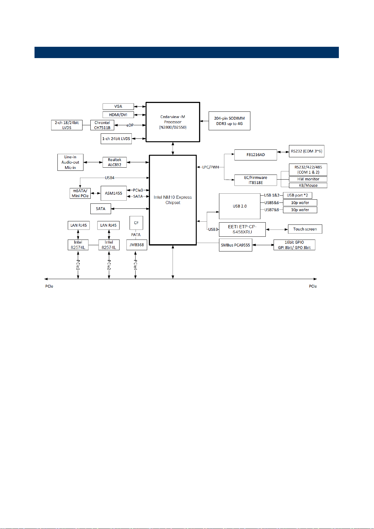
1.6 Architecture Overview—Block Diagram
The following block diagram shows the architecture and main components of EBM-CDV.
12 EBM-CDV User’s Manual

User’s Manual
13
2. Hardware
Configuration
EBM-CDV User’s Manual
EBM-CDV User’s Manual
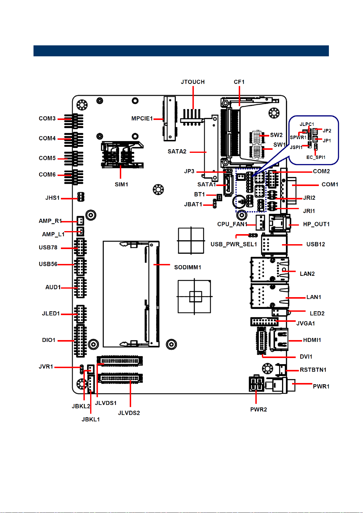
2.1 Product Overview
14 EBM-CDV User’s Manual
User’s Manual
15
Jumpers
Label
Function
Note
JBAT1
Clear CMOS
3 x 1 header, pitch 2.00mm
JP1
Serial port 1 – RS232/ 422/ 485 mode
select
4 x 3 header, pitch 2.00mm
JP2
Serial port 2 – RS232/ 422/ 485 mode
select
4 x 3 header, pitch 2.00mm
JP3
SATA Power select
3 x 1 header, pitch 2.00mm
JRI1
Serial port 1 pin9 signal select
3 x 2 header, pitch 2.00mm
JRI2
Serial port 2 pin9 signal select
3 x 2 header, pitch 2.00mm
JVR1
LCD backlight brightness adjustment
3 x 1 header, pitch 2.00mm
SW1
Serial port 1/ 2 – RS232/ 422/ 485
mode select
DIP switch 6pin
SW2
Multi-function select
DIP switch 6pin
JHS1
Handset Speaker Out selector
3 x 2 header, pitch 2.00mm
2.2 Jumper and Connector List
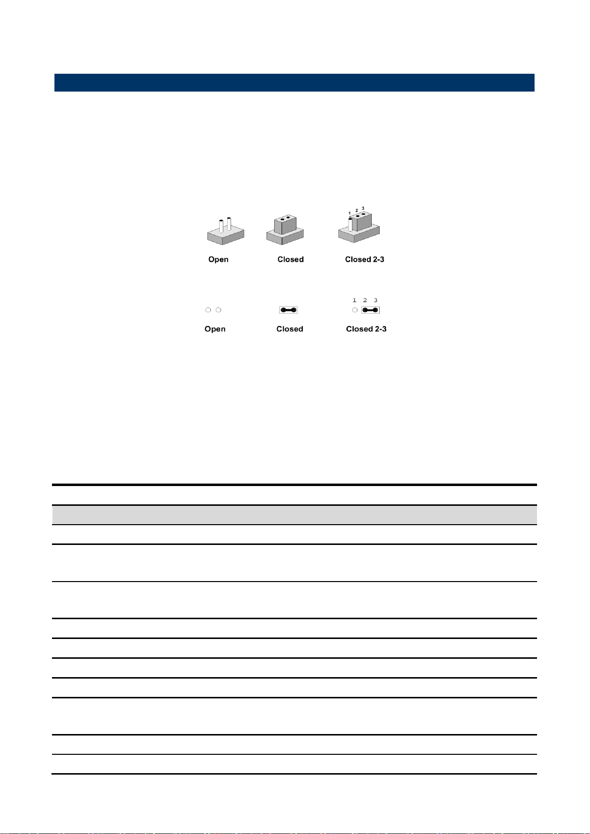
You can configure your board to match the needs of your application by setting jumpers. A
jumper is the simplest kind of electric switch.
It consists of two metal pins and a small metal clip (often protected by a plastic cover) that
slides over the pins to connect them. To “close” a jumper you connect the pins with the clip.
To “open” a jumper you remove the clip. Sometimes a jumper will have three pins, labeled 1,
2, and 3. In this case, you would connect either two pins.
The jumper settings are schematically depicted in this manual as follows:
A pair of needle-nose pliers may be helpful when working with jumpers.
Connectors on the board are linked to external devices such as hard disk drives, a
keyboard, or floppy drives. In addition, the board has a number of jumpers that allow you to
configure your system to suit your application.
If you have any doubts about the best hardware configuration for your application, contact
your local distributor or sales representative before you make any changes.
The following tables list the function of each of the board’s jumpers and connectors.
EBM-CDV User’s Manual

EBM-CDV User’s Manual
USB_PWR_SEL1
USB Power select
3 x 1 header, pitch 2.00mm
Connectors
Label
Function
Note
CF1
Compact Flash card connector
COM1
Serial Port 1 connector
D-sub 9 pin, male
CPU_FAN
CPU fan connector
3 x 1 wafer, pitch 2.54mm
SODIMM1
204-pin DDR3 SODIMM socket
AUD1
Audio connector
6 x 2 wafer, pitch 2.00mm
JBKL1
LCD Inverter connector
5 x 1 wafer, pitch 2.00mm
JBKL2
LCD Inverter connector
2 x 1 wafer, pitch 2.00mm
COM2
Serial Port 2 connector
5 x 2 wafer, pitch 2.00mm
COM3
Serial Port 3 connector
5 x 2 wafer, pitch 2.00mm
COM4
Serial Port 4 connector
5 x 2 wafer, pitch 2.00mm
COM5
Serial Port 5 connector
5 x 2 wafer, pitch 2.00mm
COM6
Serial Port 6 connector
5 x 2 wafer, pitch 2.00mm
DIO1
General purpose I/O connector
10 x 2 wafer, pitch 2.00mm
JLED1
LED indicator connector1
5 x 2 wafer, pitch 2.00mm
LED2
HDD/Power LED indicator
JLVDS1
LVDS Connector
DIN 40-pin wafer, pitch 1.25mm
JLVDS2
LVDS Connector
DIN 40-pin wafer, pitch 1.25mm
JTOUCH
Touch panel connector
5 x 1 header, pitch 2.54mm
USB12
USB connector 1&2
USB56
USB connector 5&6
5 x 2 wafer, pitch 2.00mm
USB78
USB connector 7&8
5 x 2 wafer, pitch 2.00mm
DVI1
DVI connector
10 x 2 wafer, pitch 1.25mm
LAN1
RJ-45 Ethernet 1
LAN2
RJ-45 Ethernet 1
BT1
Battery connector
2 x 1 wafer, pitch 1.25mm
AMP_R1
AMPLIFIER_R1
2 x 1 wafer, pitch 2.00mm
AMP_L1
AMPLIFIER_L1
2 x 1 wafer, pitch 2.00mm
MPCIE1
Mini-PCI connector 1
JLPC1
LPC connector
7 x 2 header, pitch 2.00mm
PWR1
Power connector
PWR2
Power connector
2 x 2 wafer, pitch 4.2mm
RSBTN
Reset button
JSPI1
SPI connector
4 x 2 header, pitch 2.00mm
EC_SPI1
EC_Program
4 x 2 header, pitch 2.00mm
SPWR1
SATA Power connector 1
2 x 1 wafer, pitch 2.00mm
SATA1
Serial ATA connector 1
16 EBM-CDV User’s Manual

User’s Manual
17
SATA2
Serial ATA connector 2
SIM1
SIM card slot
HDMI1
HDMI connector
HP_OUT1
Handphone_out connector
JVGA1
VGA connector
8 x 2 wafer, pitch 2.00mm
EBM-CDV User’s Manual
EBM-CDV User’s Manual
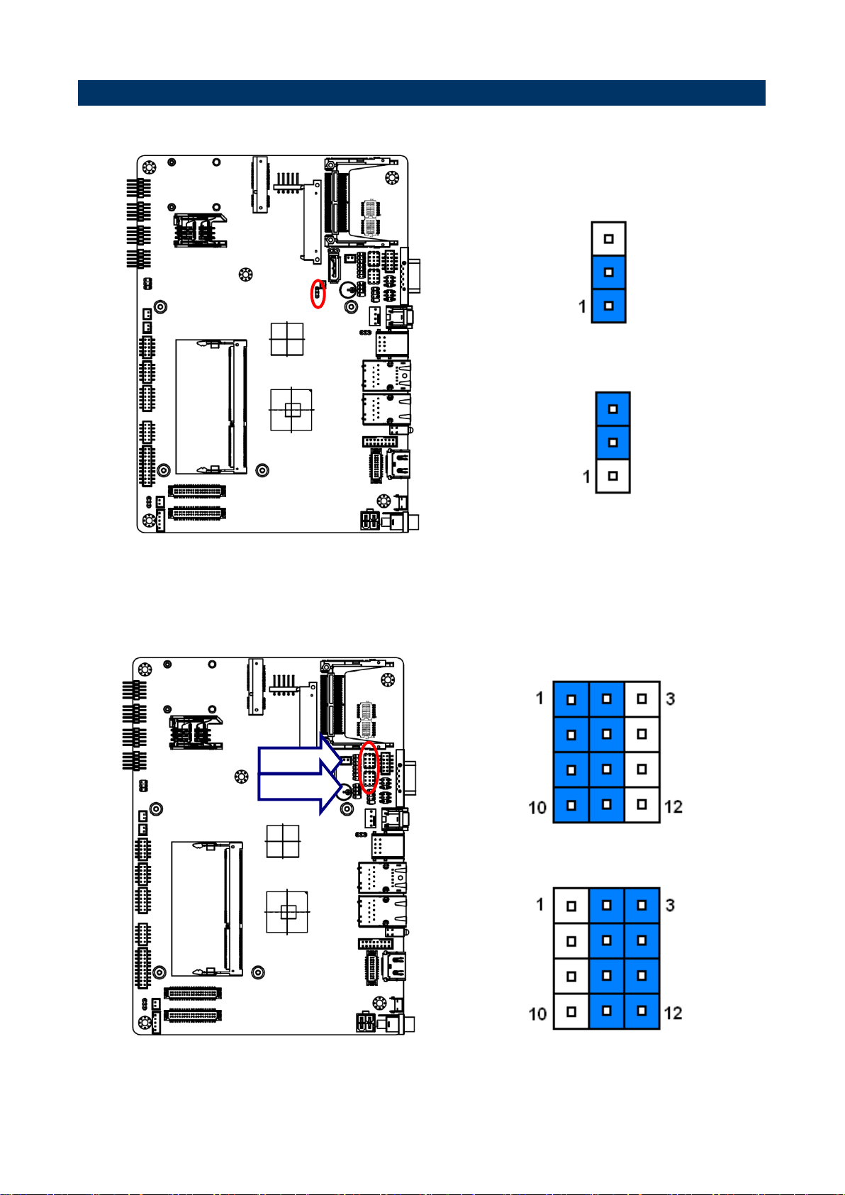
* Default
Protect*
Clear CMOS
* Default
RS-232*
RS-422/ 485
JP2
JP1
2.3 Setting Jumpers & Connectors
2.3.1 Clear CMOS (JBAT1)
2.3.2 Serial port 1/ 2 RS-232/ 422/ 485 mode select (JP1/ JP2)
18 EBM-CDV User’s Manual
User’s Manual
19
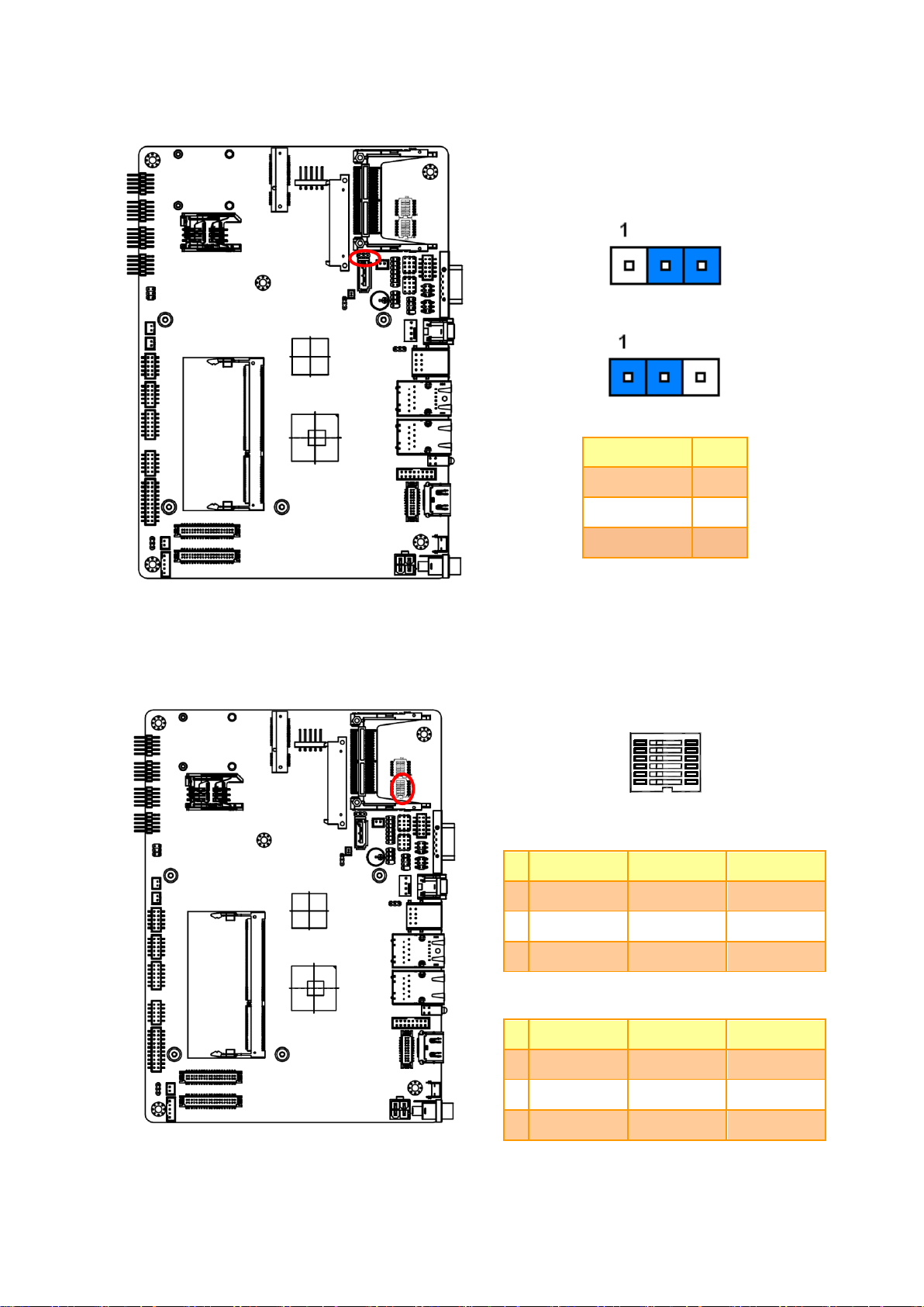
* Default
Signal
PIN
SATA_PWR1
1
SATA1 P7
2
GND
3
In Serial Port 1 mode
RS-232
RS-422
RS-485
1
ON
OFF
OFF
2
OFF
ON
OFF
3
OFF
OFF
ON
In Serial Port 2 mode
RS-232
RS-422
RS-485
4
ON
OFF
OFF
5
OFF
ON
OFF
6
OFF
OFF
ON
2.3.3 SATA Power select (JP3)
2.3.4 Serial port 1/ 2 – RS232/ 422/ 485 mode select (SW1)
EBM-CDV User’s Manual
EBM-CDV User’s Manual
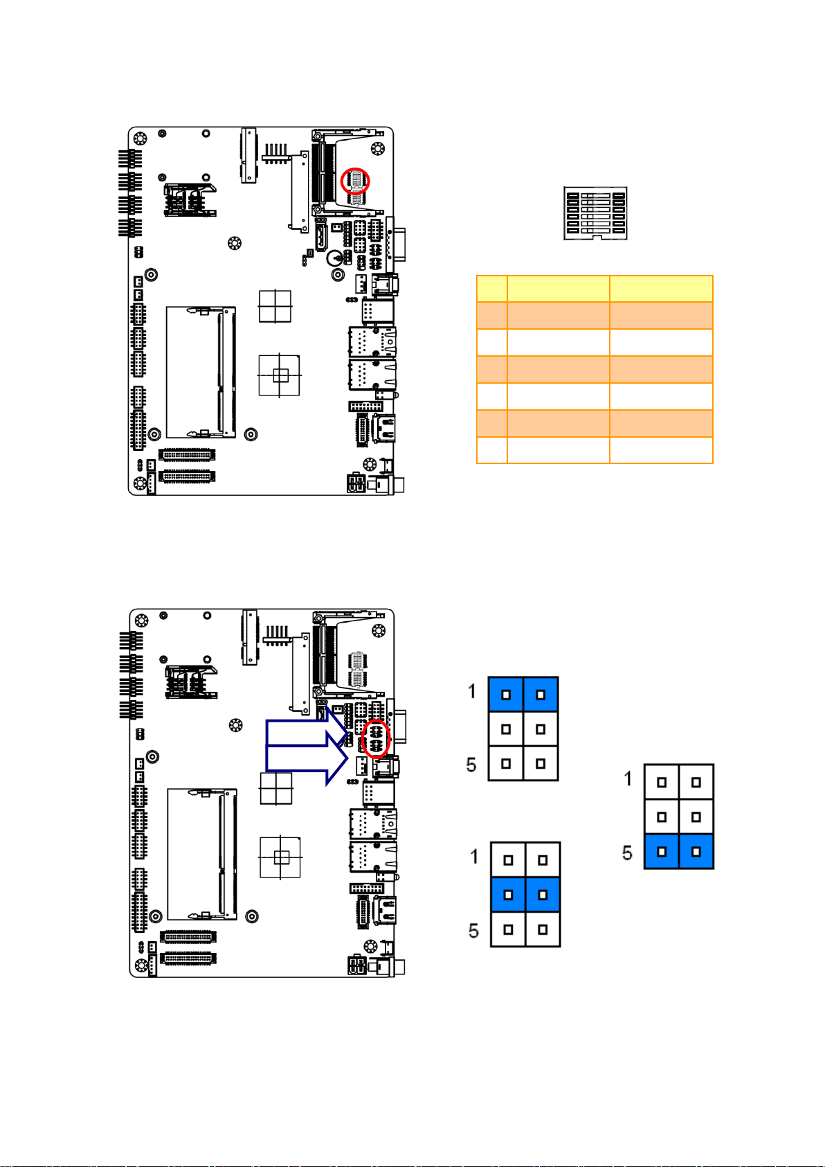
ON
OFF
1
AT SEL
ATX SEL
2
CF Master
CF Slave
3
Touch off
Touch on
4
Touch: 4W
Touch: 5W
5
GPIO38:L
GPIO38:H
6
GPIO39:L
GPIO39:H
* Default
Ring*
+5V
+12V
JRI2
JRI1
2.3.5 Multi-function select (SW2)
2.3.6 Serial port 1/ 2 pin9 signal select (JRI1/ JRI2)
20 EBM-CDV User’s Manual

User’s Manual
21
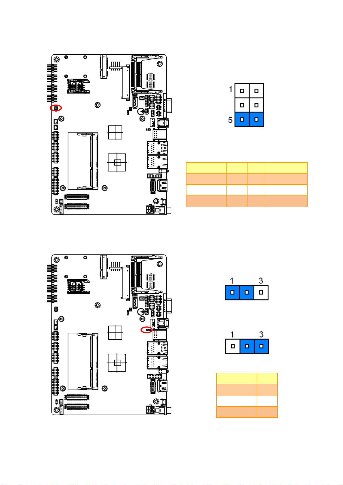
* Default
Variation Resistor
(Recommended: 4.7KΩ, >1/16W)
Signal
PIN
+5V
1
VBRIGHT
2
GND
3
2.3.7 LCD backlight brightness adjustment (JVR1)
Note:
For inverters with adjustable Backlight function, it is possible to control the LCD brightness
through the VR signal controlled by JBKL1. Please see the JBKL1 section for detailed circuitry
information.
EBM-CDV User’s Manual
EBM-CDV User’s Manual
* Default
Signal
PIN
PIN
Signal
HS_MIC+
1 2 HS_MIC-
HS_OUT+
3 4 GND
HOOK
5 6 GND
* Default
Signal
PIN
+V5A
1
USB_EN
2
+V5S
3
2.3.8 Handset Speaker Out selector (JHS1)
2.3.9 USB Power select (USB_PWR_SEL1)
22 EBM-CDV User’s Manual
User’s Manual
23
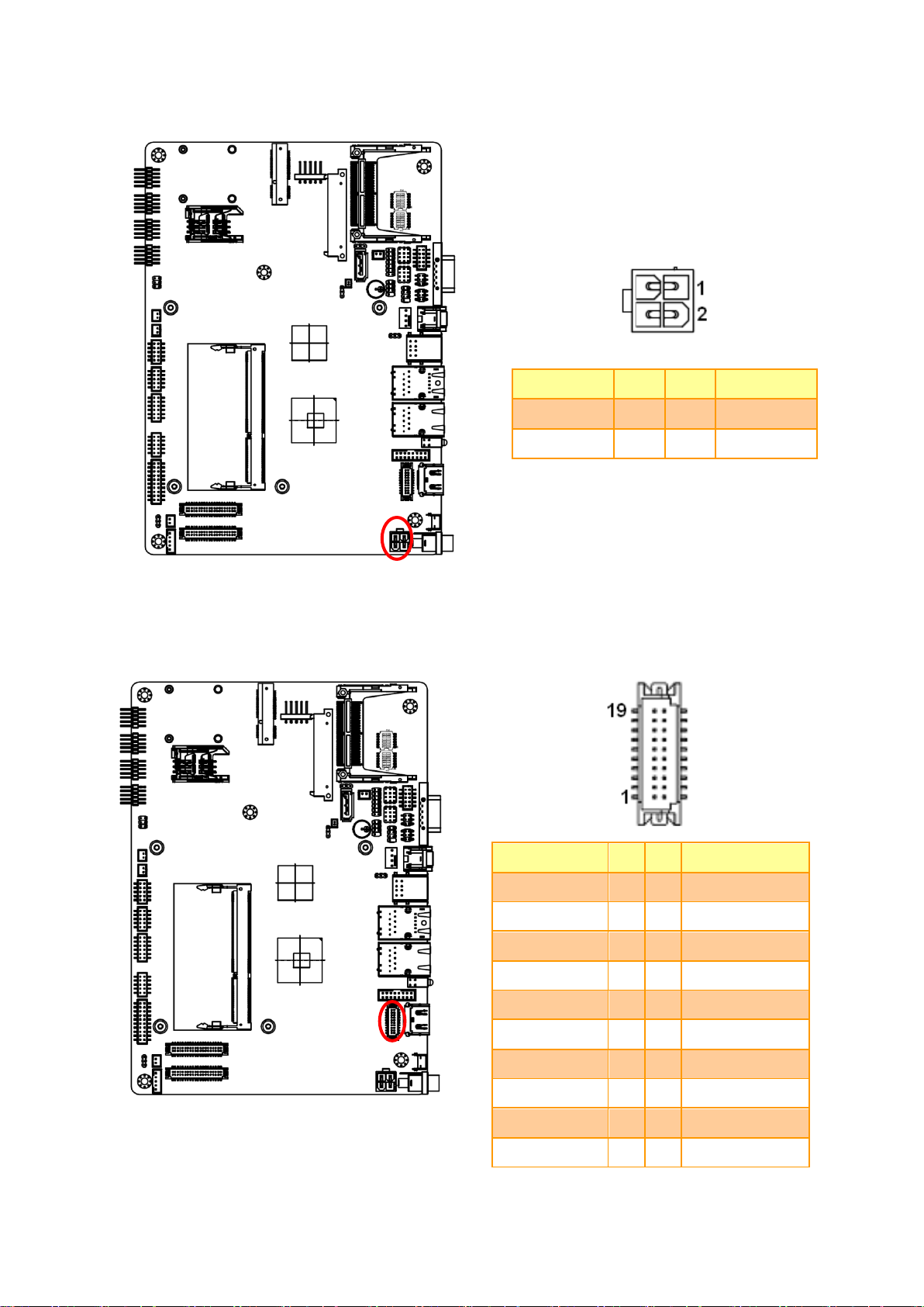
Signal
PIN
PIN
Signal
VIN
3
1
GND
VIN
4 2 GND
Signal
PIN
PIN
Signal
DVI_TXP2
19
20
DVI_CLK_P
DVI_TXN2
17
18
DVI_CLK_N
NC
15
16
GND
NC
13
14
HDMI_SCLK
DVI_TXP1
11
12
HDMI_SDATA
DVI_TXN1
9
10
HDMI_HPD
NC
7 8 NC
NC
5 6 NC
DVI_TXP0
3 4 GND
DVI_TXN0
1 2 +V5_CRT_HDMI
2.3.10 Power connector (PWR2)
2.3.11 DVI connector (DVI1)
EBM-CDV User’s Manual
EBM-CDV User’s Manual
Signal
PIN
+5V
5
VBRIGHT
4
BKLEN
3
GND
2
+12V
1
2.3.12 LCD Inverter connector (JBKL1)
Note:
For inverters with adjustable Backlight function, it is possible to control the LCD brightness through
the VR signal controlled by JVR1. Please see the JVR1 section for detailed circuitry information.
24 EBM-CDV User’s Manual
User’s Manual
25
Signal
PIN
+12V
2
GND
1
Signal
PIN
+V3P3S
4
EC_TACH0
3
+12V
2
GND
1
2.3.13 LCD Inverter connector (JBKL2)
2.3.14 CPU fan connector (CPU_FAN1)
EBM-CDV User’s Manual

EBM-CDV User’s Manual
Signal
PIN
PIN
Signal
NRIB#
9
10
NC
NRTSB#
7 8 NCTSB#
GND
5 6 NDSRB#
COM2-3
3 4 COM2-4
COM2-1
1 2 COM2-2
Signal
PIN
PIN
Signal
RXD
2 1 DCD#
DTR#
4 3 TXD
DSR#
6 5 GND
CTS#
8 7 RTS#
NC
10 9 RI#
JCOM3
JCOM4
JCOM3
JCOM5
JCOM6
2.3.15 Serial port 2 connector (COM2)
2.3.16 Serial port 3/ 4/ 5/ 6 connector (COM3/ COM4/ COM5/ COM6)
26 EBM-CDV User’s Manual

User’s Manual
27
Signal
PIN
PIN
Signal
GND
9
10
PWRBTN#
+V3P3A
7 8 LED2_ACT
+V3P3A
5 6 LED1_ACT
+V3P3S
3 4 HDD_LED#
+V3P3S
1 2 GND
2.3.17 LED indicator connector (JLED1)
EBM-CDV User’s Manual

EBM-CDV User’s Manual
Signal
PIN
PIN
Signal
+5V
19
20
GND
SMB_DATA
17
18
SMB_CLK
DO7
15
16
DI7
DO6
13
14
DI6
DO5
11
12
DI5
DO4
9
10
DI4
DO3
7 8 DI3
DO2
5 6 DI2
DO1
3 4 DI1
DO0
1 2 DI0
2.3.18 General purpose I/O connector (DIO1)
28 EBM-CDV User’s Manual

User’s Manual
29
Signal
PIN
PIN
Signal
+V5S
2 1 +V3P3S
+V5S
4 3 +V3P3S
DDC_DATA
6 5 DDC_CLK
GND
8 7 GND
A_DATA0
10 9 A_DATA1
A_DATA0#
12
11
A_DATA1#
GND
14
13
GND
A_DATA2
16
15
A_DATA3
A_DATA2#
18
17
A_DATA3#
GND
20
19
GND
NC
22
21
NC
NC
24
23
NC
GND
26
25
GND
NC
28
27
NC
NC
30
29
NC
GND
32
31
GND
LVDS1A_CLK
34
33
NC
LVDS1A_CLK#
36
35
NC
GND
38
37
GND
+V12S
40
39
+V12S
2.3.19 LVDS connector (JLVDS1)
EBM-CDV User’s Manual

EBM-CDV User’s Manual
Signal
PIN
PIN
Signal
+V5S
2 1 +V3P3S
+V5S
4 3 +V3P3S
DDC_DATA
6 5 DDC_CLK
GND
8 7 GND
DATA0_P
10 9 DATA1_P
DATA0_N
12
11
DATA1_N
GND
14
13
GND
DATA2_P
16
15
DATA3_P
DATA2_N
18
17
DATA3_N
GND
20
19
GND
DATA4_P
22
21
DATA5_P
DATA4_N
24
23
DATA5_N
GND
26
25
GND
DATA6_P
28
27
DATA7_P
DATA6_N
30
29
DATA7_N
GND
32
31
GND
CLK1_P
34
33
CLK2_P
CLK1_N
36
35
CLK2_N
GND
38
37
GND
+V12S
40
39
+V12S
2.3.20 LVDS connector (JLVDS2)
Note: Single/Dual 24-bit LVDS
1. CRT's resolution < LCD's resolution.
If we boot from CRT & LCD, the resolution is fixed by CRT's resolution.
If we boot from LCD only and plug the CRT in the OS, LCD works well but the CRT will have wrong
resolution.
2. CRT's resolution > LCD's resolution.
Everything is fine.
30 EBM-CDV User’s Manual

User’s Manual
31
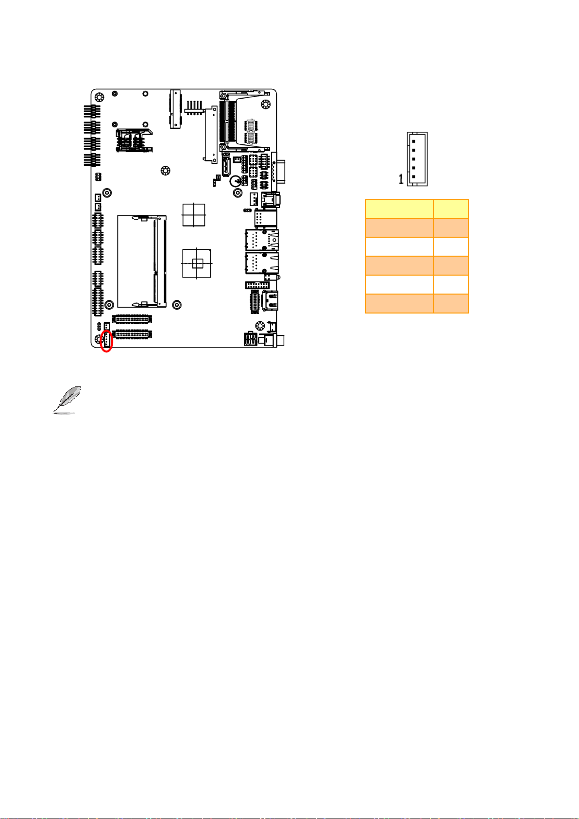
Signal
PIN
UL
1
UR
2
PROBE
3
LR
4
LL
5
NOTE: Under 4W situation
UL=X+, UR=Y+, LR=Y-, LL=X-
Signal
PIN
PIN
Signal
GND
9
10
GND
GND
7 8 GND
USB_PP5
5 6 USB_PP4
USB_NP5
3 4 USB_NP4
+VCC_USB45
1 2 +VCC_USB45
2.3.21 Touch panel connector (JTOUCH)
2.3.22 USB connector 5&6 (USB56)
EBM-CDV User’s Manual

EBM-CDV User’s Manual
Signal
PIN
PIN
Signal
GND
9
10
GND
GND
7 8 GND
USB_PP7
5 6 USB_PP6
USB_NP7
3 4 USB_NP6
+VCC_USB6
1 2 +VCC_USB6
Signal
PIN
VBAT
1
GND
2
2.3.23 USB connector 7&8 (USB78)
2.3.24 Battery connector (BT1)
32 EBM-CDV User’s Manual

User’s Manual
33
Signal
PIN
PIN
Signal
GND
11
12
MIC1_JD
LINE1_JD
9
10
FRONT_JD
MIC_LIN
7 8 MIC_RIN
LINE1_LIN
5 6 LINE1-RIN
GND
3 4 GND
LINEOUT_L
1 2 LINEOUT_R
Signal
PIN
AMP_ROUT+
1
AMP_ROUT-
2
2.3.25 Audio connector (AUD1)
2.3.26 AMPLIFIER_R1 (AMP_R1)
EBM-CDV User’s Manual

EBM-CDV User’s Manual
Signal
PIN
AMP_LOUT+
1
AMP_LOUT-
2
Signal
PIN
PIN
Signal
CRT_R
2 1 +V5_CRT_HDMI
CRT_G
4 3 GND
CRT_B
6 5 NC
NC
8 7 SDT_DDC
GND
10 9 VGA_HS
GND
12
11
VGA_VS
GND
14
13
SCK_DDC
GND
16
15
GND
2.3.27 AMPLIFIER_L1 (AMP_L1)
2.3.28 VGA connector (JVGA1)
34 EBM-CDV User’s Manual

User’s Manual
35
Signal
PIN
PIN
Signal
LPC_AD0
1 2 +V3P3S
LPC_AD1
3 4 PLTRST#
LPC_AD2
5 6 LPC_LFRAME#
LPC_AD3
7 8 CLK_PCI_JLPC
SERIRQ
9
10
GND
+V5S
11
12
GND
+V5A
13
14
LPC_LDRQ0#
Signal
PIN
PIN
Signal
+V3P3A_SPI
1 2 GND
SPI_R_CS#
3 4 SPI_CLK
SPI_SO
5 6 SPI_SI
SPI_HOLD#
7
8
2.3.29 LPC connector (JLPC1)
2.3.30 SPI connector (JSPI1)
EBM-CDV User’s Manual

EBM-CDV User’s Manual
Signal
PIN
PIN
Signal
+VSPI_EC
1 2 GND
EC_FSCE#
3 4 EC_FSCK
EC_FMISO
5 6 EC_FMOSI
EC_HOLD#
7
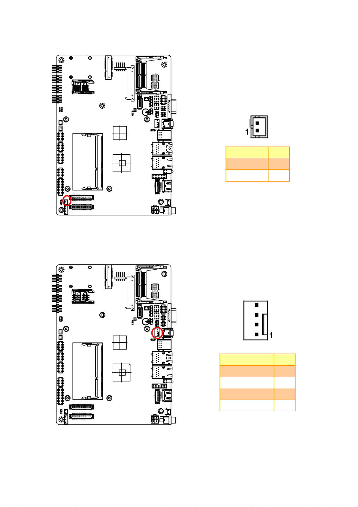
Signal
PIN
SATA_PWR1
2
GND
1
2.3.31 EC_Program (EC_SPI1)
2.3.32 SATA Power connector 1 (SPWR1)
36 EBM-CDV User’s Manual

User’s Manual
37
3.BIOS Setup
EBM-CDV User’s Manual

EBM-CDV User’s Manual
3.1 Introduction
The BIOS setup program allows users to modify the basic system configuration. In this
following chapter will describe how to access the BIOS setup program and the
configuration options that may be changed.
3.2 Starting Setup
The AMI BIOS™ is immediately activated when you first power on the computer. The BIOS
reads the system information contained in the CMOS and begins the process of checking
out the system and configuring it. When it finishes, the BIOS will seek an operating system
on one of the disks and then launch and turn control over to the operating system.
While the BIOS is in control, the Setup program can be activated in one of two ways:
By pressing <Del> immediately after switching the system on, or
By pressing the <Del> key when the following message appears briefly at the bottom of the
screen during the POST (Power On Self Test).
Press DEL to enter SETUP
If the message disappears before you respond and you still wish to enter Setup, restart the
system to try again by turning it OFF then ON or pressing the "RESET" button on the
system case. You may also restart by simultaneously pressing <Ctrl>, <Alt>, and <Delete>
keys. If you do not press the keys at the correct time and the system does not boot, an error
message will be displayed and you will again be asked to.
Press F1 to Continue, DEL to enter SETUP
38 EBM-CDV User’s Manual

User’s Manual
39
Button
Description
↑
Move to previous item
↓
Move to next item
←
Move to the item in the left hand
→
Move to the item in the right hand
Esc key
Main Menu -- Quit and not save changes into CMOS
Status Page Setup Menu and Option Page Setup Menu -- Exit current page and
return to Main Menu
PgUp key
Increase the numeric value or make changes
PgDn key
Decrease the numeric value or make changes
+ key
Increase the numeric value or make changes
- key
Decrease the numeric value or make changes
F1 key
General help, only for Status Page Setup Menu and Option Page Setup Menu
F2 key
Previous Values.
F3 key
Optimized defaults
F4 key
Save & Exit Setup
3.3 Using Setup
In general, you use the arrow keys to highlight items, press <Enter> to select, use the
PageUp and PageDown keys to change entries, press <F1> for help and press <Esc> to
quit. The following table provides more detail about how to navigate in the Setup program
using the keyboard.
Navigating Through The Menu Bar
Use the left and right arrow keys to choose the menu you want to be in.
Note: Some of the navigation keys differ from one screen to another.
To Display a Sub Menu
Use the arrow keys to move the cursor to the sub menu you want. Then press
<Enter>. A “” pointer marks all sub menus.
EBM-CDV User’s Manual

EBM-CDV User’s Manual
3.4 Getting Help
Press F1 to pop up a small help window that describes the appropriate keys to use and the
possible selections for the highlighted item. To exit the Help Window press <Esc> or the F1
key again.
3.5 In Case of Problems
If, after making and saving system changes with Setup, you discover that your computer no
longer is able to boot, the AMI BIOS supports an override to the CMOS settings which
resets your system to its defaults.
The best advice is to only alter settings which you thoroughly understand. To this end, we
strongly recommend that you avoid making any changes to the chipset defaults. These
defaults have been carefully chosen by both Award and your systems manufacturer to
provide the absolute maximum performance and reliability. Even a seemingly small change
to the chipset setup has the potential for causing you to use the override.
40 EBM-CDV User’s Manual

User’s Manual
41
3.6 BIOS setup
Once you enter the AMI BIOS CMOS Setup Utility, the Main Menu will appear on the
screen. The Main Menu allows you to select from several setup functions and exit choices.
Use the arrow keys to select among the items and press <Enter> to accept and enter the
sub-menu.
3.6.1 Main Menu
This section allows you to record some basic hardware configurations in your computer and
set the system clock.
3.6.1.1 System Language
Use this option to select system language
3.6.1.2 System Date
Use the system time option to set the system time. Manually enter the hours, minutes and
seconds.
3.6.1.3 System Time
Use the system Date option to set the system date. Manually enter the day, month and
year.
Note: BIOS setup screens shown in this chapter are for reference only, and may
not exactly match what you see on your screen. Visit the Avalue website
(www.avalue.com.tw) to download the latest product and BIOS information.
EBM-CDV User’s Manual

EBM-CDV User’s Manual
Item
Options
Description
Launch PXE OpROM
Disabled,
Enabled[Default]
Enable or disable Boot Option for Legacy
Network Devices
Launch Storage OpROM
Disabled,
Enabled[Default]
Enable or disable Boot Option for Legacy
Mass storage devices With Option ROM.
3.6.2 Advanced BIOS settings
This section allows you to configure your CPU and other system devices for basic operation
through the following sub-menus.
3.6.2.1 PCI Subsystem Settings
42 EBM-CDV User’s Manual

User’s Manual
43
Item
Options
Description
PCI Latency Timer
32 PCI Bus Clocks[Default]
64 PCI Bus Clocks
96 PCI Bus Clocks
128 PCI Bus Clocks
160 PCI Bus Clocks
192 PCI Bus Clocks
224 PCI Bus Clocks
248 PCI Bus Clocks
Value to be programmed into PCI Latency
Timer Register.
VGA Palette Snoop
Disabled[Default]
Enabled
Enables or Disables VGA Palette registers
Snooping.
PERR# Generation
Disabled[Default]
Enabled
Enables or Disables PCI Device to Generate
PERR#
SERR# Generation
Disabled[Default]
Enabled
Enables or Disables PCI Device to Generate
SERR#
Item
Options
Description
Enable ACPI Auto Configuration
Disabled,
Enabled[Default]
Enables or Disables BIOS ACPI Auto
Configuration.
Enable Hibernation
Disabled,
Enabled[Default]
Enables or Disables System ability to
Hibernate (OS/S4 Sleep State). This
option may be not effective with some
OS.
ACPI Sleep State
Suspend Disabled,
S3 (Suspend to RAM) [Default]
Select the highest ACPI sleep state
the system will enter, when the
SUSPEND button is pressed.
Lock Legacy Resources
Disabled,
Enabled[Default]
Enables or Disables Lock of Legacy
Resources.
3.6.2.2 ACPI Settings
You can use this item to set up ACPI Configuration.
EBM-CDV User’s Manual

EBM-CDV User’s Manual
S3 video Repost
Disabled[Default]
Enabled
Enable or Disable S3 video repost
DeepS5
Disabled[Default],
Enabled
Enter DeepS5.
Item
Options
Description
Wake system with Fixed Time
Disabled[Default],
Enabled
Enables or Disables wake on alarm event.
When enabled, System will wake on the
hr::min::sec specified.
Wake system with Dynamic
Time
Disabled[Default],
Enabled
Enables or Disables wake on alarm event.
When enabled, System will wake on the
current time + Increase minutes (s)
3.6.2.3 S5 RTC Wake settings
44 EBM-CDV User’s Manual

User’s Manual
45
Item
Options
Description
Hyper-Threading
Disabled[Default],
Enabled
This item allows you to enable or disable
Intel® Hyper Threading technology.
Execute Disable Bit
Disabled[Default],
Enabled
This item allows you to enable or disable the
No-Execution page protection technology.
Limit CPUID Maximum
Disabled[Default],
Enabled
This item allows you to limit CPUID maximum
Value.
3.6.2.4 CPU Configuration
Use the CPU configuration menu to view detailed CPU specification and configure the
CPU.
EBM-CDV User’s Manual

EBM-CDV User’s Manual
Item
Options
Description
DTS SMM
Enabled
Disabled[Default]
Critical Temp reporting (Out of Spec)
Disabled: ACPI thermal management uses EC
reported temperature values.
Enabled: ACPI thermal management uses
DTS SMM mechanism to obtain CPU
temperature values.
Out of spec: ACPI thermal management uses
EC reported temperature values and DTS
SMM is used to handle Out of spec condition.
3.6.2.5 Thermal Configuration
3.6.2.5.1 CPU Thermal Configuration
46 EBM-CDV User’s Manual

User’s Manual
47
Item
Options
Description
Critical Trip Point
POR[Default]
15C
23C
31C
39C
47C
55C
63C
71C
79C
87C
95C
103C
111C
119C
127C
This value controls the temperature of the
ACPI Critical Trip Point – the point in which the
OS will shut the sytem off. NOTE: 100C is the
Plan Of Record (POR) for all Intel mobile
processors.
Active Trip Point Lo Fan Speed
Disabled
15C
23C
31C
39C
47C
55C
63C
71C
79C
87C
95C
103C
111C
119C
This value controls the temperature of the
ACPI Active Trip Point – the point in which the
OS will turn the processor fan on low.
Active Trip Point Hi Fan Speed
Passive Trip Point
This value controls the temperature of the
ACPI Passive Trip Point - the point in which
the OS will begin throttling the processor.
3.6.2.5.2 Platform Thermal Configuration
EBM-CDV User’s Manual

EBM-CDV User’s Manual
Passive TC1 Value
1 – 16
This value sets the TC1 -2 value for the ACPI
Passive Cooling Formula. Range 1 - 16
Passive TC2 Value
Passive TSP Value
2 - 32
This item sets the TSP value for the ACPI
Passive Cooling Formula. It represents in
tenths of a second how often the OS will read
the temperature when passive cooling is
enabled Range 2- 32
Item
Options
Description
SATA Controller(s)
Disabled
Enabled[Default]
SATA Ports (0-3) Device Names if Present
and Enabled.
Configure SATA as
IDE[Default]
AHCI
Select a configuration for SATA Controller
3.6.2.6 IDE Configuration
48 EBM-CDV User’s Manual

User’s Manual
49
Item
Options
Description
iFFS Support
Enabled
Disabled[Default]
Enable or Disable iFFS
3.6.2.7 Intel Fast Flash Standby
3.6.2.8 USB Configuration
The USB configuration menu is used to read USB configuration information and configure
USB.
EBM-CDV User’s Manual

EBM-CDV User’s Manual
Item
Options
Description
Legacy USB support
Enabled[Default]
Disabled
Auto
Enables Legacy USB support.
AUTO disables legacy support if no USB devices are
connected. DISABLE will keep USB devices
available only for EFI applications.
ECHI Hand-off
Enabled
Disabled[Default]
This is a workaround for OSes without EHCI hand-off
support. The EHCI ownership change should be
claimed by EHCI driver.
USB transfer time-out
1sec / 5sec
10sec /
20sec[Default]
The time-out value for Control, Bulk, and Interrupt
transfers.
Device reset time-out
10sec /
20sec[Default]
30sec / 40sec
USB mass storage device Start Unit command
time-out.
Device power-up delay
Auto[Default]
Manual
Maximum time the device will take before it properly
reports itself to the Host Controller. “Auto” uses
default value: for a Root port it is 100ms, for a Hub
port the delay is taken from Hub descriptor.
Generic STORAGE DEVICE
9407
Auto
Floppy
Forced FDD
Hard Disk
CD-ROM
Mass storage device emulation type. ‘AUTO’
enumerates devices less than 530MB as floppies.
Forced FDD option can be used to force HDD
formatted drive to boot as FDD (e.g. ZIP drive).
Item
Option
Description
Smart Fan Function
Enabled,
Disabled[Default]
Enables or Disables Smart Fan
Smart Fan Mode Configuration
Smart Fan Mode Select
3.6.2.9 H/W Monitor
The H/W Monitor shows the operating temperature, fan speeds and system voltages.
50 EBM-CDV User’s Manual

User’s Manual
51
Item
Option
Description
CPU Smart Fan Mode
Manual Mode[Default]
Mode 01-20
CPU Smart Fan Mode Select
Fan PWM
0 - 255
Fan PWM duty
Item
Options
Description
SMART Self Test
Enabled[Default]
Disabled
Run SMART Self Test on all HDDs during POST.
3.6.2.9.1 Smart Fan Mode Configuration
3.6.2.10 Smart settings
EBM-CDV User’s Manual

EBM-CDV User’s Manual
Item
Description
Serial Port1 Configuration
Set Parameters of Serial Port 1 (COMC)
Serial Port1 Configuration
Set Parameters of Serial Port 2 (COMD)
Serial Port1 Configuration
Set Parameters of Serial Port 3 (COME)
Serial Port1 Configuration
Set Parameters of Serial Port 4 (COMF)
3.6.2.11 Second Super IO Configuration
You can use this item to set up or change the Second Super IO configuration for FDD
controllers, parallel ports and serial ports. Please refer to 3.6.2.9.1-4 for more information.
52 EBM-CDV User’s Manual

User’s Manual
53
Item
Option
Description
Serial Port
Enabled,
Disabled[Default]
Enable or Disable Serial Port
(COM)
Change Settings
Auto[Default]
IO=3F8h; IRQ=3,
IO=3F8h; IRQ=3,4,5,6,7,9,10,11,12
IO=2F8h; IRQ=3,4,5,6,7,9,10,11,12
IO=3E8h; IRQ=3,4,5,6,7,9,10,11,12
IO=2E8h; IRQ=3,4,5,6,7,9,10,11,12
Select an optimal setting for
Super IO device.
3.6.2.11.1 Serial Port 1 Configuration
3.6.2.11.2 Serial Port 2 Configuration
EBM-CDV User’s Manual

EBM-CDV User’s Manual
Item
Option
Description
Serial Port
Enabled,
Disabled[Default]
Enable or Disable Serial Port
(COM)
Change Settings
Auto[Default]
IO=2F8h; IRQ=3,
IO=3F8h; IRQ=3,4,5,6,7,9,10,11,12
IO=2F8h; IRQ=3,4,5,6,7,9,10,11,12
IO=3E8h; IRQ=3,4,5,6,7,9,10,11,12
IO=2E8h; IRQ=3,4,5,6,7,9,10,11,12
Select an optimal setting for
Super IO device.
Item
Option
Description
Serial Port
Enabled,
Disabled[Default]
Enable or Disable Serial Port
(COM)
Change Settings
Auto[Default]
IO=3E8h; IRQ=3,
IO=3F8h; IRQ=3,4,5,6,7,9,10,11,12
IO=2F8h; IRQ=3,4,5,6,7,9,10,11,12
IO=3E8h; IRQ=3,4,5,6,7,9,10,11,12
IO=2E8h; IRQ=3,4,5,6,7,9,10,11,12
IO=2F0h; IRQ=3,4,5,6,7,9,10,11,12
IO=2E0h; IRQ=3,4,5,6,7,9,10,11,12
Select an optimal setting for
Super IO device.
3.6.2.11.3 Serial Port 3 Configuration
54 EBM-CDV User’s Manual

User’s Manual
55
Item
Option
Description
Serial Port
Enabled,
Disabled[Default]
Enable or Disable Serial Port
(COM)
Change Settings
Auto[Default]
IO=2E8h; IRQ=3,
IO=3F8h; IRQ=3,4,5,6,7,9,10,11,12
IO=2F8h; IRQ=3,4,5,6,7,9,10,11,12
IO=3E8h; IRQ=3,4,5,6,7,9,10,11,12
IO=2E8h; IRQ=3,4,5,6,7,9,10,11,12
IO=2F0h; IRQ=3,4,5,6,7,9,10,11,12
IO=2E0h; IRQ=3,4,5,6,7,9,10,11,12
Select an optimal setting for
Super IO device.
3.6.2.11.4 Serial Port 4 Configuration
EBM-CDV User’s Manual

EBM-CDV User’s Manual
Item
Option
Description
Watch Dog
Disabled[Default]
30sec
40sec
50sec
1min
2min
10min
30min
Select WatchDog.
PWRON After PWR-Fail
Off[Default]
On
Former-Sts
Select PWRON After PWR-Fail.
3.6.2.12 Super IO Configuration
You can use this item to set up or change the Super IO configuration for FDD controllers, parallel
ports and serial ports. Please refer to 3.6.2.10.1 and 3.6.2.10.2 for more information.
56 EBM-CDV User’s Manual

User’s Manual
57
Item
Option
Description
Serial Port
Disabled[Default]
Enabled,
Enable or Disable Serial Port
(COM)
Change Settings
Auto[Default]
IO=3F8h; IRQ=4,
IO=3F8h; IRQ=3,4,5,6,7,9,10,11,12
IO=2F8h; IRQ=3,4,5,6,7,9,10,11,12
IO=3E8h; IRQ=3,4,5,6,7,9,10,11,12
IO=2E8h; IRQ=3,4,5,6,7,9,10,11,12
Select an optimal setting for
Super IO device.
Device Mode
Normal[Default]
High Speed
Change the Serial Port mode.
Select <High Speed> or <Normal
mode> mode
3.6.2.12.1 Serial Port 0 Configuration
EBM-CDV User’s Manual

EBM-CDV User’s Manual
Item
Option
Description
Serial Port
Disabled[Default]
Enabled,
Enable or Disable Serial Port
(COM)
Change Settings
Auto[Default]
IO=2F8h; IRQ=3,
IO=3F8h; IRQ=3,4,5,6,7,9,10,11,12
IO=2F8h; IRQ=3,4,5,6,7,9,10,11,12
IO=3E8h; IRQ=3,4,5,6,7,9,10,11,12
IO=2E8h; IRQ=3,4,5,6,7,9,10,11,12
Select an optimal setting for
Super IO device.
Device Mode
Normal[Default]
High Speed
Change the Serial Port mode.
Select <High Speed> or <Normal
mode> mode
3.6.2.12.2 Serial Port 1 Configuration
58 EBM-CDV User’s Manual

User’s Manual
59
Item
Option
Description
EIST
Disabled[Default]
Enabled
Enable/Disable Intel SpeedStep.
CPU C state Report
Disabled[Default]
Enabled
Enable/Disable CPU C state
report to OS.
Enhanced C state
Disabled[Default]
Enabled
Enable/Disable Enhanced CPU C
state.
CPU Hard C4E
Disabled[Default]
Enabled
Enable/Disable CPU Hard C4E
function.
CPU C6 state
Disabled[Default]
Enabled
Enable/Disable CPU C6 state.
C4 Exit Timing
Default[Default]
Fast
Slow
This option controls a
programmable time for the CPU
voltage to stabilize when exiting
from a C4 state.
C-state POPDOWN
Disabled[Default]
Enabled
Disabling the option, prevents
automatic return to a previous C3
or C4 state.
C-state POPUP
Disabled[Default]
Enabled
On enabled, SB observes bus
master request, will take system
from a C3/C4 state to a C2 state
and auto enables bus masters.
3.6.2.13 PPM configuration
EBM-CDV User’s Manual

EBM-CDV User’s Manual
Item
Description
Host Bridge
Host Bridge Parameters
South Bridge
South Bridge Parameters
3.6.3 Advanced Chipset Features
3.6.3.1 Host bridge
60 EBM-CDV User’s Manual

User’s Manual
61
Item
Description
Memory Frequency and Timing
Config Memory Frequency and Timing Settings.
Intel IGD Configuration
Config Intel IGD Settings.
3.6.3.1.1 Host Bridge
3.6.3.1.1.1 Intel IGD Configuration
EBM-CDV User’s Manual

EBM-CDV User’s Manual
Item
Option
Description
VBIOS Version
1053
1059
1071[Default]
Select the VBIOS version.
IGFX – Boot Type
VBIOS Default[Default]
CRT
CRT + LVDS
CRS + HDMI (Twin)
LVDS
LVDS + CRT
HDMI
HDMI + LVDS
Select the Video Device which will
be activated during POST. This
has no effect if external graphics
present.
Panel Scaling
Auto[Default]
Force Scaling
Off
Maintain Aspect Ratio
Select the LCD panel scaling
option used by the Internal
Graphics Device.
Active LFP
No LVDS
LVDS[Default]
Select the Active LFP
Configuration. No LVDS:VBIOS
does not enable LVDS.
Int-LVDS:VBIOS enables LVDS
driver by Integrated encoder.
SDVO LVDS:VBIOS enables
LVDS driver by SDVO encoder.
eDP Port-A:LFP Driven by
Int-DispalyPort encoder from
Port-A. eDP Port-D:LFP Driven by
Int-DisplayPort encoder from
Port-D(through PCH).
CH7511 EDID Panel Option
1024x768 24/1 [Default]
800x600 18/1
1024x768 18/1
1366x768 18/1
1024x600 18/1
1280x800 18/1
1920x1200 24/2
640x840 18/1
800x480 18/1
1920x1080 18/2
1280x1024 24/2
1440x900 18/2
1600x1200 24/2
1366x768 24/1
1920x1080 24/2
1680x1050 24/2
Port1-EDP to LVDS(Chrotel
7511) Panel EDID Option
LVDS Back Light PWM
100%[Default]
75%
50%
25%
0%
Select LVDS back light PWM
duty.
LVDS Back Light PWM
Frequency
200[Default]
300
400
500
700
1K
2K
3K
5K
Select LVDS back light PWM
Frequency.
IGD Clock Source
External Clock[Default]
Internal Clock
IGD clock selection.
62 EBM-CDV User’s Manual

User’s Manual
63
Fixed Graphics Memory Size
128MB[Default]
256MB
Configure Fixed Graphics
Memory Size
ALS Support
Disabled[Default]
Enabled
Valid only for ACPI. Legacy=ALS
Support through the IGD INT10
function. ACPI=ALS support
through an ACPI ALS driver.
Item
Option
Description
MRC Fast Boot
Disabled
Enabled[Default]
Enalbe or disable MRC fast boot.
Max TOLUD
Dynamic[Default]
1GB
1.25GB
1.5GB
1.75GB
2GB
2.25GB
2.5GB
2.75GB
3GB
3.25GB
Maximum Value of TOLUD.
Dynamic assignment would adjust
TOLUD automatically based on
largest MMIO length of installed
graphic controller.
3.6.3.1.1.2 Memory Frequency and Timing
EBM-CDV User’s Manual

EBM-CDV User’s Manual
Item
Option
Description
PCI Express Port 0
Disabled
Enabled[Default]
Enable / Disable PCI Express
Root Port 0.
Port 0 IOxAPIC
Disabled[Default]
Enabled
Enable / Disable PCI Express
Root Port 0 I/O APIC
Automatic ASPM
Manual[Default]
Auto
Automatically enable ASPM
based on reported capabilities
and known issues
3.6.3.2 South bridge
3.6.3.2.1 PCI Express Root Port 0
64 EBM-CDV User’s Manual

User’s Manual
65
ASPM L0s
Disabled[Default]
Root Port Only
End point Port Only
Both Root And Endpoint Ports
Enable PCIe ASPM L0s
ASPM L1
Disabled[Default]
Enabled
Enable PCIe ASPM L1
URR
Disabled[Default]
Enabled
PCI Express Unsupported
Request Reporting
Enable/Disable.
FER
Disabled[Default]
Enabled
PCI Express Device Fatal Error
Reporting Enable/Disable
NFER
Disabled[Default]
Enabled
PCI Express Device Non-Fatal
Error Reporting Enable/Disable.
CER
Disabled[Default]
Enabled
PCI Express Device correctable
Error Reporting Enable/Disable
CTO
Disabled[Default]
Enabled
PCI Express Completion Timer
TO Enable/Disable
SEFE
Disabled[Default]
Enabled
Root PCI Express System Error
on Fatal Error Enable/Disable
SENFE
Disabled[Default]
Enabled
Root PCI Express System Error
on Non-Fatal Error
Enable/Disable
SECE
Disabled[Default]
Enabled
Root PCI Express Error on
Correctable Error Enable/Disable
PME SCI
Disabled
Enabled[Default]
PCI Express PME SCI
Enable/Disable.
Hot Plug
Disabled[Default]
Enabled
PCI Express Hot Plug
Enable/Disable
Extra Bus Reserved
0 - 7
Extra Bus Reserved (0 -7)for
bridges behind this Root Bridge.
Reserved Memory
1 – 20MB
Reserved memory and
Prefetchable Memory (1-20MB)
Range for this Root Bridge.
Reserved I/O
4K/8K/12K/16K/20K
Reserved I/O
(4K/8K/12K/16K/20K) Range for
this Root Bridge.
3.6.3.2.2 PCI Express Root Port 1/2/3
EBM-CDV User’s Manual

EBM-CDV User’s Manual
66 EBM-CDV User’s Manual

User’s Manual
67
Item
Option
Description
PCI Express Port 0
Auto[Default]
Enabled
Disabled
Enable / Disable PCI Express
Root Port 0.
Port 0 IOxAPIC
Enabled
Disabled[Default]
Enable / Disable PCI Express
Root Port 0 I/O APIC
Automatic ASPM
Manual[Default]
Auto
Automatically enable ASPM
based on reported capabilities
and known issues
ASPM L0s
Disabled[Default]
Root Port Only
Endpoint Port Only
Both Root And Endpoint Ports
Enable PCIe ASPM L0s
ASPM L1
Enabled
Disabled[Default]
Enable PCIe ASPM L1
URR
Enabled
Disabled[Default]
PCI Express Unsupported
Request Reporting
Enable/Disable.
FER
Enabled
Disabled[Default]
PCI Express Device Fatal Error
Reporting Enable/Disable
NFER
Enabled
Disabled[Default]
PCI Express Device Non-Fatal
Error Reporting Enable/Disable.
CER
Enabled
Disabled[Default]
PCI Express Device correctable
Error Reporting Enable/Disable
CTO
Enabled
Disabled[Default]
PCI Express Completion Timer
TO Enable/Disable
SEFE
Enabled
Disabled[Default]
Root PCI Express System Error
on Fatal Error Enable/Disable
SENFE
Enabled
Disabled[Default]
Root PCI Express System Error
on Non-Fatal Error
Enable/Disable
SECE
Enabled
Disabled[Default]
Root PCI Express System Error
on Correctable Error
Enable/Disable
PME SCI
Enabled[Default]
Disabled
PCI Express PME SCI
Enable/Disable.
Hot Plug
Enabled
Disabled[Default]
PCI Express Hot Plug
Enable/Disable
EBM-CDV User’s Manual

EBM-CDV User’s Manual
Extra Bus Reserved
0 - 7
Extra Bus Reserved (0 -7)for
bridges behind this Root Bridge.
Reserved Memory
1 – 20MB
Reserved Memory and
Prefetchable Memory (1-20MB)
Range for this Root Bridge.
Reserved I/O
4K/8K/12K/16K/20K
Reserved I/O
(4K/8K/12K/16K/20K) Range for
this Root Bridge.
Item
Option
Description
Azalia Controller
Disabled
HD Audio[Default]
Azalia controller
Select USB Mode
By Ports
By controllers[Default]
Select USB mode to control USB
ports
UHCI #1 (ports 0 and 1)
Enabled[Default]
Disabled
Control the USB UHCI (USB1.1)
functions. Disable from highest to
lowest controller.
UHCI #2 (ports 2 and 3)
Enabled[Default]
Disabled
UHCI #3 (ports 4 and 5)
Enabled[Default]
Disabled
UHCI #4 (ports 6 and 7)
Enabled[Default]
Disabled
USB 2.0(EHCI) Support
Enabled[Default]
Disabled
Enable or Disable USB 2.0
(EHCI) Support.
SMBus Controller
Enabled[Default]
Disabled
Enable or Disable OnChip SMBus
Controller.
SIRQ Logic
Enabled[Default]
Disabled
Enable or Disable SIRQ logic
SIRQ Mode
Quiet
Continous[Default]
Set SIRQ mode.
3.6.3.2.3 TPT Devices
68 EBM-CDV User’s Manual

User’s Manual
69
Item
Option
Description
Setup Prompt Timeout
1~65535
Number of seconds to wait for
setup activation key.
65535(0xFFFF) means indefinite
waiting.
Bootup NumLock State
On
Off[Default]
Select the keyboard NumLock
state
Quiet Boot
Enabled
Disabled[Default]
Enables or Disables Quiet Boot
Option
Fast Boot
Enables or Disables boot with initialization of a minimal set of devices
required to launch active boot option. Has no effect for BBS boot
options
GateA20 Active
Upon Request[Default]
Always
UPON REQUEST –GA20 can be
disabled using BIOS services.
ALWAYS- do not allow disabling
GA20; this option is useful when
any RT code is executed above
1MB
Option ROM Messages
Force BIOS[Default]
Keep current
Set display mode for Option ROM
INT19 Trap Response
Immediate[Default]
Postponed
BIOS reaction on INT19 trapping
by Option ROM:
IMMEDIATE-execute the trap
right away:
POSTPONED-execute the trap
during legacy boot.
CSM Support
Disabled
Enabled[Default]
Auto
Enable/Disable CSM Support. If
Auto is selected, based on OS,
CSM will be enabled/disabled
automatically.
Boot Option #1/2/3
Sets the system boot order
3.6.4 Boot settings
EBM-CDV User’s Manual

EBM-CDV User’s Manual
3.6.5 Security
Use the Security menu to set system and user password.
3.6.5.1 Administrator Password
This setting specifies a password that must be entered to access the BIOS Setup Utility. If
only the Administrator's password is set, then this only limits access to the BIOS setup
program and is only asked for when entering the BIOS setup program. By default, no
password is specified.
3.6.5.2 User Password
This setting specifies a password that must be entered to access the BIOS Setup Utility or
to boot the system. If only the User's password is set, then this is a power on password and
must be entered to boot or enter the BIOS setup program. In the BIOS setup program, the
User will have Administrator rights. By default, no password is specified.
70 EBM-CDV User’s Manual

User’s Manual
71
3.6.6 Save & Exit
3.6.6.1 Save Changes and Exit
Use the save changes and reset option to save the changes made to the BIOS options and
to exit the BIOS configuration setup program.
3.6.6.2 Discard Changes and Exit
Use the Discard changes and Exit option to exit the system without saving the changes
made to the BIOS configuration setup program.
EBM-CDV User’s Manual

EBM-CDV User’s Manual
3.6.6.3 Save Changes and Reset
Any changes made to BIOS settings are stored in NVRAM. The setup program then exits
and reboots the controller.
3.6.6.4 Discard Changes and Reset
Any changes made to BIOS settings during this session of the BIOS setup program are
discarded. The setup program then exits and reboots the controller.
3.6.6.5 Save Changes
Changes made to BIOS settings during this session are committed to NVRAM. The setup
program remains active, allowing further changes.
3.6.6.6 Discard Changes
Any changes made to BIOS settings during this session of the BIOS setup program are
discarded. The BIOS setup continues to be active.
3.6.6.7 Restore Defaults
This option restores all BIOS settings to the factory default. This option is useful if the
controller exhibits unpredictable behavior due to an incorrect or inappropriate BIOS setting.
3.6.6.8 Save as user defaults
This option saves a copy of the current BIOS settings as the User Defaults. This option is
useful for preserving custom BIOS setup configurations.
3.6.6.9 Restore user defaults
This option restores all BIOS settings to the user defaults. This option is useful for restoring
previously preserved custom BIOS setup configurations.
3.6.6.10 Boot override
This option lists all possible bootable devices and allows the user to override the Boot
Option Priorities list for the current boot. If no changes have been made to the BIOS setup
options, the system will continue booting to the selected device without first rebooting. If
BIOS setup options have been changed and saved, a reboot will be required and the boot
override selection will not be valid.
72 EBM-CDV User’s Manual

User’s Manual
73
4. Drivers Installation
Note: Installation procedures and screen shots in this section are
for your reference and may not be exactly the same as
shown on your screen.
EBM-CDV User’s Manual

EBM-CDV User’s Manual
Insert the Supporting DVD-ROM to
DVD-ROM drive, click on “start” icon and it
should show the index page of Avalue’s
products automatically. If not, locate the
folder HTML and choose the product from
the targeted folder.
Note: The installation procedures and
screen shots in this section are
based on W7 operating system.
Step 1. Locate 「\VGA\EBM-CDV_VGA」.
Step 4. Select Next to continue installation.
Step 2. Select Next to start setup.
Step 5. Select Install to continue installation.
Step 3. Select Yes to the next step.
Step 6. Select Next to continue installation.
4.1 Install VGA Driver
74 EBM-CDV User’s Manual

User’s Manual
75
Step 7. Select Finish to complete installation
EBM-CDV User’s Manual

EBM-CDV User’s Manual
Insert the Supporting DVD-ROM to
DVD-ROM drive, click on “start” icon and it
should show the index page of Avalue’s
products automatically. If not, locate the
folder HTML and choose the product from
the targeted folder.
Note: The installation procedures and
screen shots in this section are
based on W7 operating system.
Step 1. Locate
「\Driver_Chipset\Intel\EBM-C
DV-INF」.
Step 4. Select Next to continue installation.
Step 2. Select Next to start setup.
Step 5. Select Next to continue installation.
Step 3. Select Yes to the next step.
Step 6. Select Finish to complete
installation
4.2 Install Chipset Driver (Cedarview)
76 EBM-CDV User’s Manual

User’s Manual
77
Insert the Supporting DVD-ROM to DVD-ROM
drive, click on “start” icon and it should show the
index page of Avalue’s products automatically. If
not, locate the folder HTML and choose the
product from the targeted folder.
Note: The installation procedures and screen
shots in this section are based on W7
operating system.
Step 2. Select Next to the next step.
Step 1. Locate
「\Driver_Audio\Realtek\ALC892\EBM-CDV-audio」.
Step 3. Installing.
4.3 Install Audio Driver (For Realtek ALC892)
EBM-CDV User’s Manual

EBM-CDV User’s Manual
Insert the Supporting DVD-ROM to
DVD-ROM drive, click on “start” icon and it
should show the index page of Avalue’s
products automatically. If not, locate the
folder HTML and choose the product from
the targeted folder.
Note: The installation procedures and
screen shots in this section are based
on W7 operating system.
Step 3. Click Next.
Step 1. Locate
「\Driver_Gigabit\Intel\82574L\EBM-CDV-LAN」
Step 4. Click Next to accept licence
agreement.
Step 2. Click Yes.Next.
Step 5. Click Next after selecting programs to
install.
4.4 Install Ethernet Driver (For Realtek 82574L)
78 EBM-CDV User’s Manual

User’s Manual
79
Step 6. Click Install to begin installation
Step 8. Click Finish to complete installation
Step 7. Wait while installing.
EBM-CDV User’s Manual

EBM-CDV User’s Manual
5. Mechanical Drawing
80 EBM-CDV User’s Manual

User’s Manual
81
Unit: mm
EBM-CDV User’s Manual

EBM-CDV User’s Manual
Unit: mm
82 EBM-CDV User’s Manual
 Loading...