


EAX-Q87R
Intel® LGA1150 Socket Supports 4th Generation Core™
Refresh i7/ i5/ i3, Pentium® and Celeron® Processors ATX
Motherboard With Intel® Q87 Express Chipset
User’s Manual
1st Ed – 23 January 2015
Part No: E2047A87R00R

EAX-Q87R User’s Manual
FCC Statement
Ne
Disclaimer
Life Support Policy
THIS DEVICE COMPLIES WITH PART 15 FCC RULES. OPERATION IS
SUBJECT TO THE FOLLOWING TWO CONDITIONS:
(1) THIS DEVICE MAY NOT CAUSE HARMFUL INTERFERENCE.
(2) THIS DEVICE MUST ACCEPT ANY INTERFERENCE RECEIVED INCLUDING
INTERFERENCE THAT MAY CAUSE UNDESIRED OPERATION.
THIS EQUIPMENT HAS BEEN TESTED AND FOUND TO COMPLY WITH THE LIMITS
FOR A CLASS "A" DIGITAL DEVICE, PURSUANT TO PART 15 OF THE FCC RULES.
THESE LIMITS ARE DESIGNED TO PROVIDE REASONABLE PROTECTION AGAINST
HARMFUL INTERFERENCE WHEN THE EQUIPMENT IS OPERATED IN A COMMERCIAL
ENVIRONMENT. THIS EQUIPMENT GENERATES, USES, AND CAN RADIATE RADIO
FREQUENCY ENERGY AND, IF NOT INSTALLED AND USED IN ACCORDANCE WITH
THE INSTRUCTION MANUAL, MAY CAUSE HARMFUL INTERFERENCE TO RADIO
COMMUNICATIONS.
OPERATION OF THIS EQUIPMENT IN A RESIDENTIAL AREA IS LIKELY TO CAUSE
HARMFUL INTERFERENCE IN WHICH CASE THE USER WILL BE REQUIRED TO
CORRECT THE INTERFERENCE AT HIS OWN EXPENSE.
This guide is designed for experienced users to setup the system within the shortest time.
For detailed information, please always refer to the electronic user's manual.
Copyright 2015 Avalue Technology Inc., ALL RIGHTS RESERVED.
No part of this document may be reproduced, copied, translated, or transmitted in any form
or by any means, electronic or mechanical, for any purpose, without the prior written
permission of the original manufacturer.
Brand and product names are trademarks or registered trademarks of their respective
owners.
Avalue Technology Inc. reserves the right to make changes, without notice, to any product,
including circuits and/or software described or contained in this manual in order to improve
design and/or performance. Avalue Technology assumes no responsibility or liability for the
use of the described product(s), conveys no license or title under any patent, copyright, or
masks work rights to these products, and makes no representations or warranties that these
products are free from patent, copyright, or mask work right infringement, unless otherwise
specified. Applications that are described in this manual are for illustration purposes only.
Avalue Technology Inc. makes no representation or warranty that such application will be
suitable for the specified use without further testing or modification.
2 EAX-Q87R User’s Manual

EAX-Q87R User’s Manual
3
A Message to the Customer
Avalue Technology’s PRODUCTS ARE NOT FOR USE AS CRITICAL COMPONENTS IN
LIFE SUPPORT DEVICES OR SYSTEMS WITHOUT THE PRIOR WRITTEN APPROVAL
OF Avalue Technology Inc.
As used herein:
1. Life support devices or systems are devices or systems which, (a) are intended for
surgical implant into body, or (b) support or sustain life and whose failure to perform, when
properly used in accordance with instructions for use provided in the labeling, can be
reasonably expected to result in significant injury to the user.
2. A critical component is any component of a life support device or system whose failure to
perform can be reasonably expected to cause the failure of the life support device or
system, or to affect its safety or effectiveness.
Avalue Customer Services
Each and every Avalue’s product is built to the most exacting specifications to ensure
reliable performance in the harsh and demanding conditions typical of industrial
environments. Whether your new Avalue device is destined for the laboratory or the factory
floor, you can be assured that your product will provide the reliability and ease of operation
for which the name Avalue has come to be known.
Your satisfaction is our primary concern. Here is a guide to Avalue’s customer services. To
ensure you get the full benefit of our services, please follow the instructions below carefully.
Technical Support
We want you to get the maximum performance from your products. So if you run into
technical difficulties, we are here to help. For the most frequently asked questions, you can
easily find answers in your product documentation. These answers are normally a lot more
detailed than the ones we can give over the phone. So please consult the user’s manual first.
To receive the latest version of the user’s manual; please visit our Web site at:
http://www.avalue.com.tw/
EAX-Q87R User’s Manual

EAX-Q87R User’s Manual
Product Warranty
Avalue warrants to you, the original purchaser, that each of its products will be free from
defects in materials and workmanship for two years from the date of purchase.
This warranty does not apply to any products which have been repaired or altered by
persons other than repair personnel authorized by Avalue, or which have been subject to
misuse, abuse, accident or improper installation. Avalue assumes no liability under the terms
of this warranty as a consequence of such events. Because of Avalue’s high quality-control
standards and rigorous testing, most of our customers never need to use our repair service.
If any of Avalue’s products is defective, it will be repaired or replaced at no charge during the
warranty period. For out-of-warranty repairs, you will be billed according to the cost of
replacement materials, service time, and freight. Please consult your dealer for more details.
If you think you have a defective product, follow these steps:
1. Collect all the information about the problem encountered. (For example, CPU type and
speed, Avalue’s products model name, hardware & BIOS revision number, other
hardware and software used, etc.) Note anything abnormal and list any on-screen
messages you get when the problem occurs.
2. Call your dealer and describe the problem. Please have your manual, product, and any
helpful information available.
3. If your product is diagnosed as defective, obtain an RMA (return material authorization)
number from your dealer. This allows us to process your good return more quickly.
4. Carefully pack the defective product, a complete Repair and Replacement Order Card
and a photocopy proof of purchase date (such as your sales receipt) in a shippable
container. A product returned without proof of the purchase date is not eligible for
warranty service.
5. Write the RMA number visibly on the outside of the package and ship it prepaid to your
dealer.
4 EAX-Q87R User’s Manual

EAX-Q87R User’s Manual
5
Contents
1. Getting Started .............................................................................................................. 7
1.1 Safety Precautions ...................................................................................................... 7
1.2 Packing List ................................................................................................................. 7
1.3 Document Amendment History ................................................................................... 8
1.4 System Specifications ................................................................................................. 9
1.5 Architecture Overview – Block Diagram .................................................................... 11
2. Hardware Installation ................................................................................................. 12
2.1 Product highlights ...................................................................................................... 12
2.2 Motherboard Overview .............................................................................................. 15
2.2.1 Placement Direction ................................................................................................. 15
2.2.2 Screw Holes ............................................................................................................. 15
2.2.3 Motherboard Layout ................................................................................................. 16
2.3 Jumper and Connector List ....................................................................................... 17
2.4 Central Processing Unit (CPU).................................................................................. 19
2.4.1 Installing the CPU ..................................................................................................... 20
2.4.2 Installing the CPU Heatsink and Fan ........................................................................ 22
2.5 System Memory ................................................................................................ ........ 25
2.5.1 Overview .................................................................................................................. 25
2.5.2 Memory Configurations ............................................................................................ 26
2.5.3 Installing a DIMM ...................................................................................................... 26
2.5.4 Removing a DIMM .................................................................................................... 28
2.6 Expansion Card......................................................................................................... 28
2.6.1 Installing an Expansion Card .................................................................................... 29
2.6.2 Configuring an Expansion Card ............................................................................... 29
2.6.3 PCI Express x16 slot ................................................................................................ 29
2.6.4 PCI Express x 4 slot ................................................................................................. 30
2.6.5 PCI slot ..................................................................................................................... 30
2.7 Setting Jumpers & Connectors ................................................................................. 31
2.7.1 Clear CMOS Jumper (JCMOS1) ......................................................................... 31
2.7.2 ATX/AT Mode Selection (JPSON1) .................................................................... 31
2.7.3 COM2 Ring-In/ +12V/ +5V Select (JCOMPWR1) ............................................... 32
2.7.4 Set COM2 RS-232/422/485 Mode (JSETCOM1) ................................................ 32
2.7.5 ATX Power Connectors: EATXPWR1 ................................................................. 33
2.7.6 12V ATX Power Connector (ATX12V1) .............................................................. 33
2.7.7 Serial Port 1 Connector (COM1) ......................................................................... 34
2.7.8 Serial Port 2 Connector (COM2) ......................................................................... 34
EAX-Q87R User’s Manual

EAX-Q87R User’s Manual
2.7.9 Serial Port 3~6 Connectors (COM3~6) ............................................................... 35
2.7.10 LPT Port Connector (LPT1)............................................................................... 35
2.7.11 Front Panel Connector (F_PANEL1) ................................................................. 36
2.7.12 Fan Connectors (CPU_FAN1, SYS_FAN1, CHA_FAN1) .................................. 36
2.7.13 SATA Ports (SATA1~6) ..................................................................................... 37
2.7.14 Front USB Headers (USB56, USB78, USB910, USB1112) .............................. 37
2.7.15 Front Panel Audio Connector (FPAUD1) .......................................................... 38
2.7.16 Amplifier Connector (JAMP1) ............................................................................ 38
2.7.17 Digital I/O Connector (JDIO1) ........................................................................... 39
3. BIOS Setup .................................................................................................................. 40
3.1 Introduction ............................................................................................................... 40
3.2 Starting Setup ........................................................................................................... 40
3.3 Using Setup ............................................................................................................... 41
3.4 BIOS Menu Screen ................................................................................................... 42
3.4.1 Main Setup ............................................................................................................ 43
3.4.2 Advanced BIOS Setup ........................................................................................... 44
3.4.3 Chipset .................................................................................................................. 68
3.4.4 Boot ....................................................................................................................... 80
3.4.5 Security .................................................................................................................. 81
3.4.6 Save & Exit ............................................................................................................ 82
6 EAX-Q87R User’s Manual
7
1. Getting Started
Warning!
Always disconnect the power cord from your chassis whenever you
work with the hardware. Do not make connections while the power is
on. Sensitive electronic components can be damaged by sudden
power surges. Only experienced electronics personnel should open
the PC chassis.
Caution!
Always ground yourself to remove any static charge before touching
the CPU card. Modern electronic devices are very sensitive to static
electric charges. As a safety precaution, use a grounding wrist strap at
all times. Place all electronic components in a static-dissipative
surface or static-shielded bag when they are not in the chassis
1.1 Safety Precautions
EAX-Q87R User’s Manual
1.2 Packing List
Before you begin installing the single board, make sure that the following materials are
included in the package:
1 x EAX-Q87R ATX Main board
1 x DVD-ROM contains OS drivers/User’s Manual
2 x COM cable
2 x SATA cable
1 x I/O shield
EAX-Q87R User’s Manual

EAX-Q87R User’s Manual
Revision
Date
Comment
1st
February 2015
Initial Release
1.3 Document Amendment History
This manual describes the Avalue Technology EAX-Q87R Single Board.
We have tried to include as much information as possible but have not duplicated information
that is provided in the standard IBM Technical References, unless proven to be necessary to
aid in the understanding of this board.
We strongly recommend that you read this manual carefully before attempting to install the
EAX-Q87R series or change the standard configurations. Whilst all the necessary
information is available in this manual, it is recommend to contact your supplier for guidance
for any queries and concern.
Please be aware that it is possible to create configurations within the CMOS RAM that may
make booting impossible. If this should happen, clear the CMOS settings, (see the
description of the Jumper Settings for details).
If you have any suggestions or find any errors concerning this manual and want to inform us,
please contact our Customer Service department with the relevant details.
8 EAX-Q87R User’s Manual

9
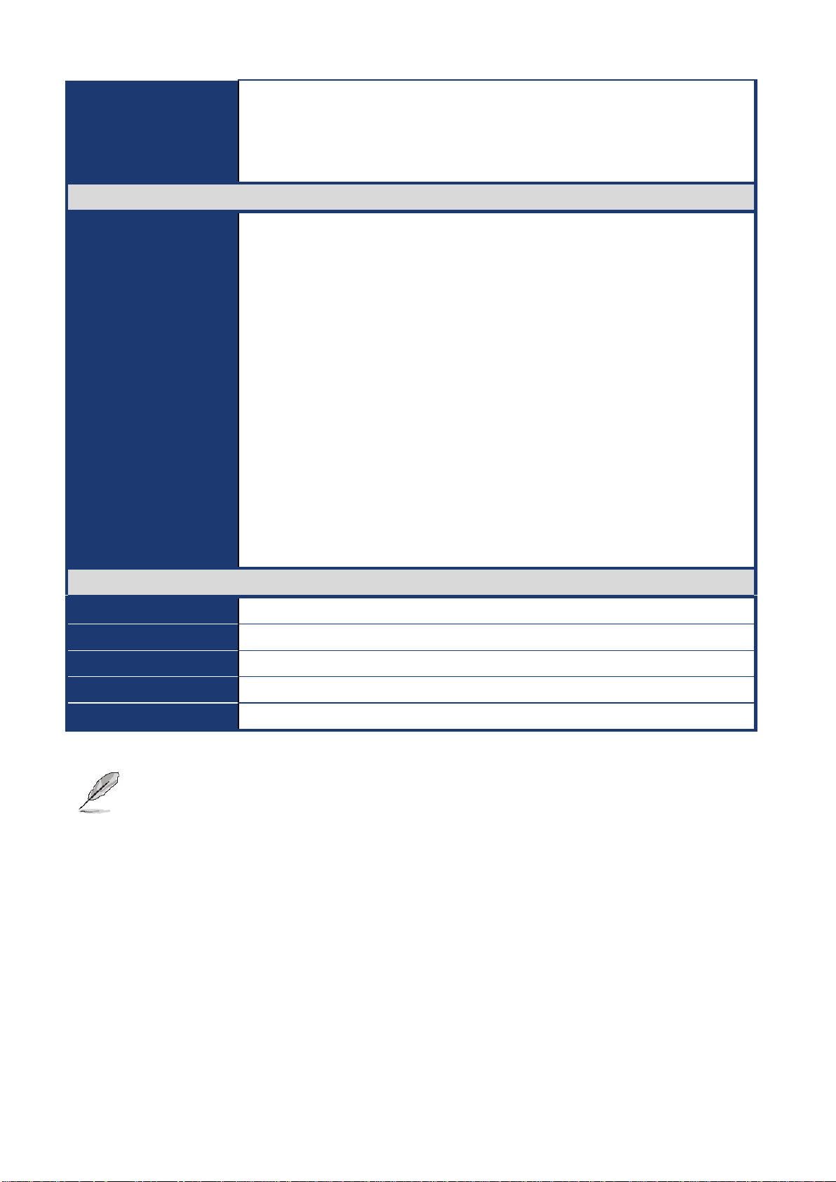
System
CPU
Intel® LGA1150 Socket Supports 4th Generation Core™ Refresh i7/ i5/ i3,
Pentium® and Celeron® Processors
BIOS
AMI uEFI BIOS, 64Mbit SPI Flash ROM
System Chipset
Intel® Q87 Express Chipset (Co-lay C226 Chipset)
I/O Chipset
Nuvoton NCT6776F
Memory
4 x 240-Pin DIMM sockets supports DDR3 memories 1600/1333 MHz up to 32GB
Watchdog Timer
Reset: 1 sec.~ 65535 sec./ min. and 1 sec. or 1 min./step
H/W Status Monitor
Monitoring temperatures, voltages with Auto throttling control
Expansion Slots
1 x PCI-E x16 slot, 1 x PCI-e x 4 slot, 1x PCI-e x 1 slot
4 x PCI slot
DIO
8 Bit GPIO
S3 / S4
Yes
Wake up on LAN or
Ring
LAN (PXE)
Smart Fan Control
Yes, CPU FAN(by SIO)
Display
Chipset
Intel® 4th Generation CPU integrated
Triple Display
1 x DVI , 1 x VGA, 1 x Display Port
VGA
Max. Resolution 1920 x 1200 @ 60 Hz
DVI
Max. Resolution 1920 x 1200 @ 60 Hz
Display Port
Max. Resolution 3840 x 2160 @ 24 Hz
Audio
Audio Codec
Realtek® ALC892, supports 5.1-CH
Audio Interface
Line-in, Line-out, Mic-in
Audio Amplifier
TI TPA3005D2 Stereo Class-D 6W x 2 Audio Amplifier connector
Ethernet
LAN1
Intel I217LM Gigabit Ethernet controller (PHY)
LAN2
Intel I210AT Gigabit Ethernet controller
Back I/O Port
Back Panel
1 x PS2 KB/ 1 x PS2 MS
1 x VGA
1 x DVI-D
1 x Display port
5 x COM Port (RS-232)
1.4 System Specifications
EAX-Q87R User’s Manual
EAX-Q87R User’s Manual
EAX-Q87R User’s Manual
1 x COM Port (RS-232/ 422/ 485)
2 x RJ45 LAN port
4 x USB 3.0
1 x 3 Audio Jacks (Line-in/ Line-out/ Mic-in)
Internal I/O Connector
Internal I/O
6 x SATAIII connectors (RAID 0, 1, 5, 10 supported)
5 x USB connectors support additional 9 x USB 2.0 ports
5 x COM header (COM2: RS-232/422/485 supported, w/ +5V&+12V supported,
selected by jumper; COM3~6, RS-232)
1 x CPU Fan connector
1 x System Fan connector
1 x Front Audio connector
1 x Front panel header
1 x Printer port
1 x 8 Bit DIO connector
1 x PS2 Keyboard/Mouse connector
1 x AT/ ATX power jumper
1 x 24-pin ATX Power connector
1 x 4-pin ATX 12V Power connector
Mechanical & Environmental
Power Type
AT/ ATX
Operating Temperature
0~60°C (32~140°F)
Operating Humidity
0%~90% relative humidity, non-condensing
Size (L x W)
12'' x 9.6'' (304.8mm x 243.84mm)
Weight
1.32lbs (0.6Kg)
Note: Specifications are subject to change without notice.
10 EAX-Q87R User’s Manual
EAX-Q87R User’s Manual
11
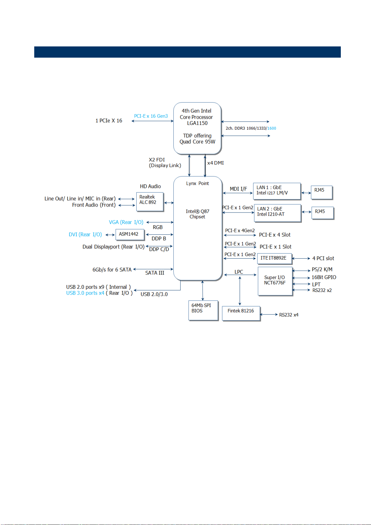
1.5 Architecture Overview – Block Diagram
The following block diagram shows the architecture and main components of EAX-Q87R.
EAX-Q87R User’s Manual

EAX-Q87R User’s Manual
2. Hardware Installation
2.1 Product highlights
2.1.1 Product Overview
Supports latest Intel LGA 1150 CPU-socket interface processor, the 4nd Generation Intel®
Core i3, i5, i7 desktop processors which are built on 22 nm technologies to provide smart
performance and responsiveness on executing tasks, It combines the CPU and GPU to offer
fantastic HD media and graphics, especially on 3D gaming experience.
DMI (Direct Media Interface) architecture connects between the processor and chipset at
5.0GT/s which twice the speed of previous version. The exceptionally increased interconnect
bit rate from 2.5GT/s up to 5.0GT/s would effectively eliminates the bottle neck of the system
performance and brings the most terrific computing experience from the present to the future.
Doubles the transfer speed of SATA 3G, running at speed up to 6.0Gb/s, and can connect
with any other SATA 3.0Gb/s and 1.5Gb/s devices for backward compatibility.
Supports RAID 0(Striped disk array), RAID 1(Mirroring disk array), RAID 5(Block Interleaved
Distributed Parity), RAID 10 (A Stripe of Mirrors). Provides users the performance and
protection. Integrated 5.1-channel HD Audio CODEC delivering advanced multi-channel
audio and bringing you the experience of home theater-quality sound. Delivers transfer
speed ten times faster than conventional 10/ 100 Ethernet connections, supporting a high
transfer rate up to Gigabit/s. Gigabit LAN is the networking standards for the future and is
ideal for handing large amount of data such as video, audio, and voice.
Choose an environment-friendly, fully RoHS-compliant ECS product as the foundation for
keeping harmful substances out of our ecosystem.
2.1.2 Platform Features and Benefits
•Integrated Gfx (Intel® HD Graphics 4000/4600) with enhanced operating modes to enable
excellent graphics performance in power and cost sensitive embedded applications
• DirectX® 11.1 & Open GL 4.0 let you enjoy awesome graphics performance, stunning 3D
visual effect and dynamic interactivity
• Memory support, integrated low voltage DDR3 memory controller
• Operating system support:
- Microsoft
12 EAX-Q87R User’s Manual

EAX-Q87R User’s Manual
13
-WindRiver
-Redhat
-Novell
-Green Hills
-QNX
- LinuxWorks
2.1.3 Key Architecture Features
• Supports Intel LGA 1150 CPU, the 4nd Generation Intel® Core i3, i5, i7 desktop
processors.
-22nm monolithic die
-Integrated Gfx (Intel® HD Graphics 4000/4600) & memory controller
-4 &2 Cores, up to 8MB LLC
-HW accelerated video CODECs
- Compatible with high speed DDR3-1600
-PCIe* (CPU): Gen 2.0, 5GT/s, up to 20 lanes (4 ctls)**
-TDP: 35W-65W (22nm Haswell Platform)
• Intel® Turbo Boost Technology
-More efficient power sharing between CPU and Graphics
• Intel® Hyper-Threading Technology
• Intel® Advanced Vector Extensions 2 (Intel® AVX2)
• Intel® Transactional Synchronization Extensions (TSX)
• Integrated Display Interfaces
- Triple Independent Display Support
- DVI-D
- Analog VGA
- Display Port
• Intel® HD Graphics 4000/4600
- DirectX® 11.1
- Improved realism for DX 3D applications. Improved rendering.
- OpenGL 4.0
- Improved realism for OGL 3D based application
- UVD (Unified Video Decoder) 2.01
Hardware decode of most common HD codecs (MPEG-2, H.264/AVC MPEG-4 and
VC-1)
- Supports ATI Hybrid CrossFireXTM Technology2
• Intel Quick Sync Video
- Enables faster and higher quality video editing, recording and sharing
• I/O
- PCI Express® x 16 Gen 3 8GT/s
EAX-Q87R User’s Manual

EAX-Q87R User’s Manual
Before you Proceed
Unplug the power cord from the wall socket before touching any
component.
Use a grounded wrist strap or touch a safely grounded object or a
metal object, such as the power supply case, before handling
components to avoid damaging them due to static electricity
Hold components by the edges to avoid touching the ICs on
them.
Whenever you uninstall any component, place it on a grounded
anti-static pad or in the bag that came with the component.
Before you install or remove any component, ensure that the ATX
power supply is switched off or the power cord is detached from
the power supply. Failure to do so may cause severe damage to
the motherboard, peripherals, and/or components.
- PCI Express® x 4Gen 3 8GT/s
- PCI 2.3 interface
- Six SATA ports (6 ports of Gen 3.0) support RAID 0,1, 5, 10
- Gigabit Ethernet Media Access Controller (GbE MAC)
IPv4 and IPv6 Checksum Offload
- High Definition Audio
- USB: Gen 2.0, up to 9 Ports / Gen 3.0, up to 4 Ports
- SMBus 2.0
- LPC Bus
Supports SPI devices
- Hardware Monitor
Fan control (Voltage, Temp)
Watchdog timer
• Power Management
- Dual Dynamic Power Management
Separate power planes for cores and memory controller
- Advanced Configuration and Power Interface (ACPI) 5.0
- AMD PowerNow! and AMD Cool’n’Quiet technologies support
Take note of the following precautions before you install motherboard components or change
any motherboard settings.
14 EAX-Q87R User’s Manual
EAX-Q87R User’s Manual
15
Make sure to unplug the power cord before installing or removing the
motherboard. Failure to do so can cause you physical injury and
damage motherboard components.
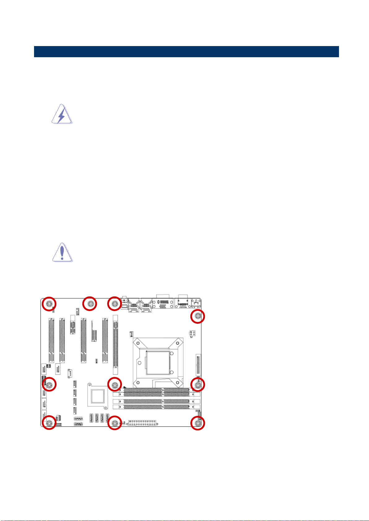
Do not over tighten the screws! Doing so can damage the
motherboard.
Place this side towards the rear of the
chassis.
2.2 Motherboard Overview
Before you install the motherboard, study the configuration of your chassis to ensure that the
motherboard fits into it. Refer to the chassis documentation before installing the
motherboard.
2.2.1 Placement Direction
When installing the motherboard, make sure that you place it into the chassis in the correct
orientation. The edge with external ports goes to the rear part of the chassis as indicated in
the image below.
2.2.2 Screw Holes
Place eight (8) screws into the holes indicated by circles to secure the motherboard to the
chassis.
EAX-Q87R User’s Manual
EAX-Q87R User’s Manual
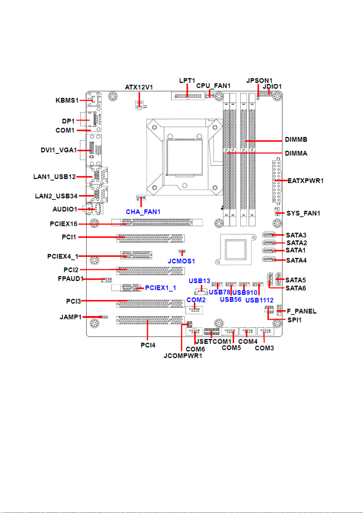
2.2.3 Motherboard Layout
16 EAX-Q87R User’s Manual
EAX-Q87R User’s Manual
17
Jumpers
Label
Function
Note
JCMOS1
Clear CMOS Jumper
JPSON1
ATX/AT Mode Selection
JCOMPWR1
COM2 Ring-In/ +12V/ +5V Select
Connectors
Label
Function
Note
VGA1
VGA Video Port
LAN1~2
Gigabit LAN
(RJ-45) Connector
AUDIO1
Line-in port (Light blue)
Line-out port (Lime)
Microphone port (Pink)
2.3 Jumper and Connector List
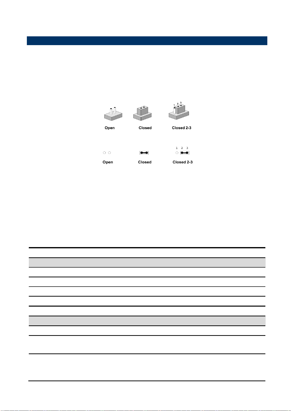
You can configure your board to match the needs of your application by setting jumpers. A
jumper is the simplest kind of electric switch.
It consists of two metal pins and a small metal clip (often protected by a plastic cover) that
slides over the pins to connect them. To “close” a jumper you connect the pins with the clip.
To “open” a jumper you remove the clip. Sometimes a jumper will have three pins, labeled 1,
2, and 3. In this case, you would connect either two pins.
The jumper settings are schematically depicted in this manual as follows:
A pair of needle-nose pliers may be helpful when working with jumpers.
Connectors on the board are linked to external devices such as hard disk drives, a keyboard,
or floppy drives. In addition, the board has a number of jumpers that allow you to configure
your system to suit your application.
If you have any doubts about the best hardware configuration for your application, contact
your local distributor or sales representative before you make any changes.
The following tables list the function of each of the board's jumpers and connectors.
EAX-Q87R User’s Manual
EAX-Q87R User’s Manual
USB
BACK PANEL USB3.0 Connector x 4
DP1
Display Port
KBMS1
PS/2 Keyboard & Mouse Connector
EATXPWR1
24pin ATX Power Connector
ATX12V1
12V ATX Power Connector
COM1
Serial port 1 Connector
COM2
Serial port 2 Connector
JSETCOM1
Set COM2 RS-232/422/485 Mode
COM3~6
Serial Port 3~6 Connectors
LPT1
LPT Port Connector
F_PANEL1
Front Panel Connector
CPU_FAN1
CPU Fan Connector
SYS_FAN1
System Fan Connector
CHA_FAN1
Fan Connector
SATA1~6
Serial ATA Connector
USB56/78/910/1112
Front USB Header
USB13
USB connector
FPAUD1
Front Panel Audio Connector
JAMP1
Amplifier Connector
JDIO1
Digital I/O Connector
PCI1~4
PCI slot
PCIEX16/4_1/1_1
PCIe Connector
DIMMA/B
DDR3 LONG DIMM Socket
SPI1
SPI Connector
DVI
DVID Video port
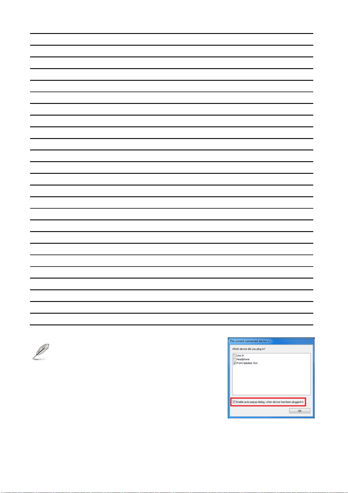
The on-screen message alerting you about
headphones being connected to the computer.
The Realtek audio software features an automatic
jack sensing option to let you know when
something has been inserted into an audio port.
18 EAX-Q87R User’s Manual
EAX-Q87R User’s Manual
19
Your boxed Intel® Core™ i7/ i5/ i3 LGA1150 processor package
should come with installation instructions for the CPU, fan and
heatsink assembly. If the instructions in this section do not match
the CPU documentation, follow the latter.
Upon purchase of the motherboard, make sure that the PnP cap
is on the socket and the socket pins are not bent. Contact your
retailer immediately if the PnP cap is missing, or if you see any
damage to the PnP cap/socket pins/motherboard components.
ADVANSUS will shoulder the cost of repair only if the damage is
shipment/transit-related.
Keep the cap after installing the motherboard. ADVANSUS will
process Return Merchandise Authorization (RMA) requests only
if the motherboard comes with the cap on the LGA1150 socket.
The product warranty does not cover damage to the socket pins
resulting from incorrect CPU installation/removal, or
misplacement/loss/incorrect removal of the PnP cap.
Install the CPU fan and heatsink assembly before you install
motherboard to the chassis.
If you purchased a separate CPU heatsink and fan assembly, make
sure that you have properly applied Thermal Interface Material to the
CPU heatsink or CPU before you install the heatsink and fan
assembly.
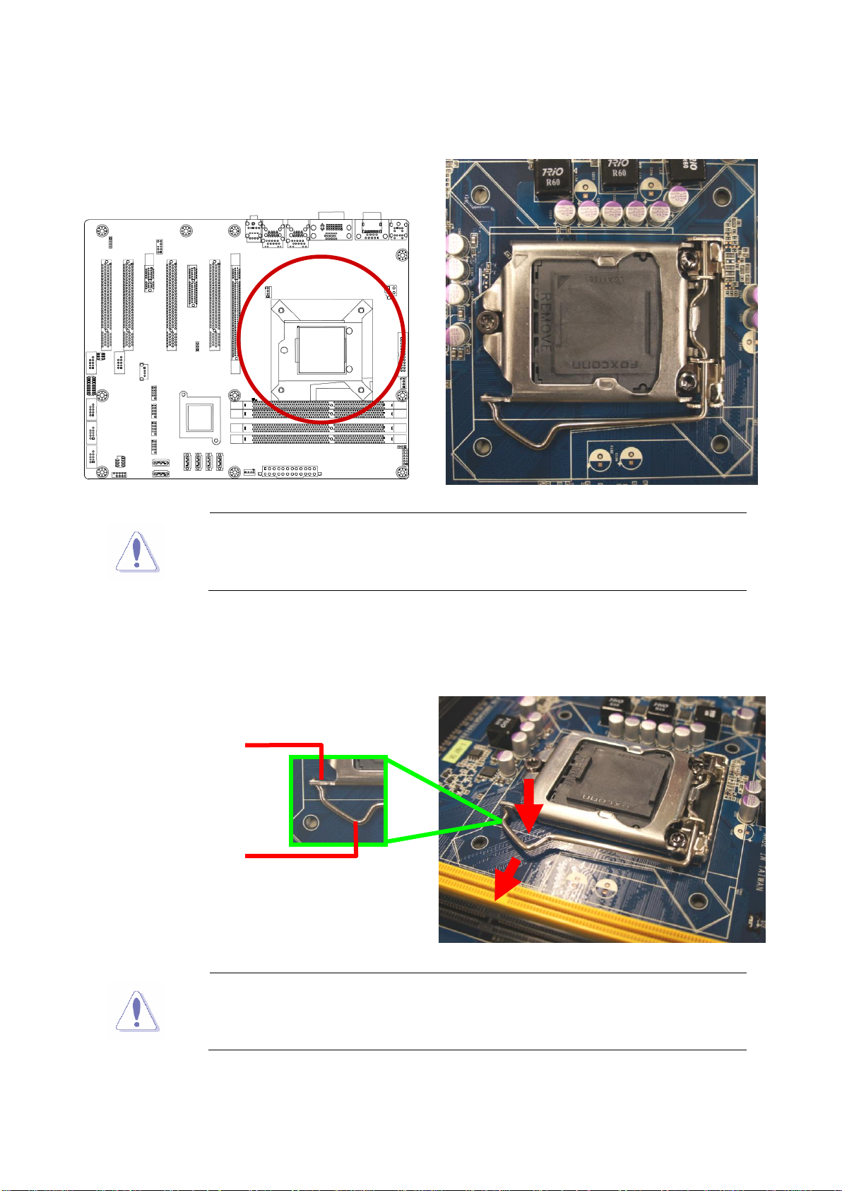
2.4 Central Processing Unit (CPU)
The motherboard comes with a surface mount LGA1150 socket designed for the Intel®
Core™ i7/ i5/ i3 processor in the 1150-land package.
EAX-Q87R User’s Manual
EAX-Q87R User’s Manual
Before installing the CPU, make sure that the socket box is facing
towards you and the load lever is on your left.
To prevent damage to the socket pins, do not remove the PnP cap
unless you are installing a CPU.
A B Retention tab
Load lever
2.4.1 Installing the CPU
1. Locate the CPU socket on the motherboard.
2. Press the load lever with your thumb (A), then move it to the left (B) until it is released
from the retention tab.
20 EAX-Q87R User’s Manual
EAX-Q87R User’s Manual
21
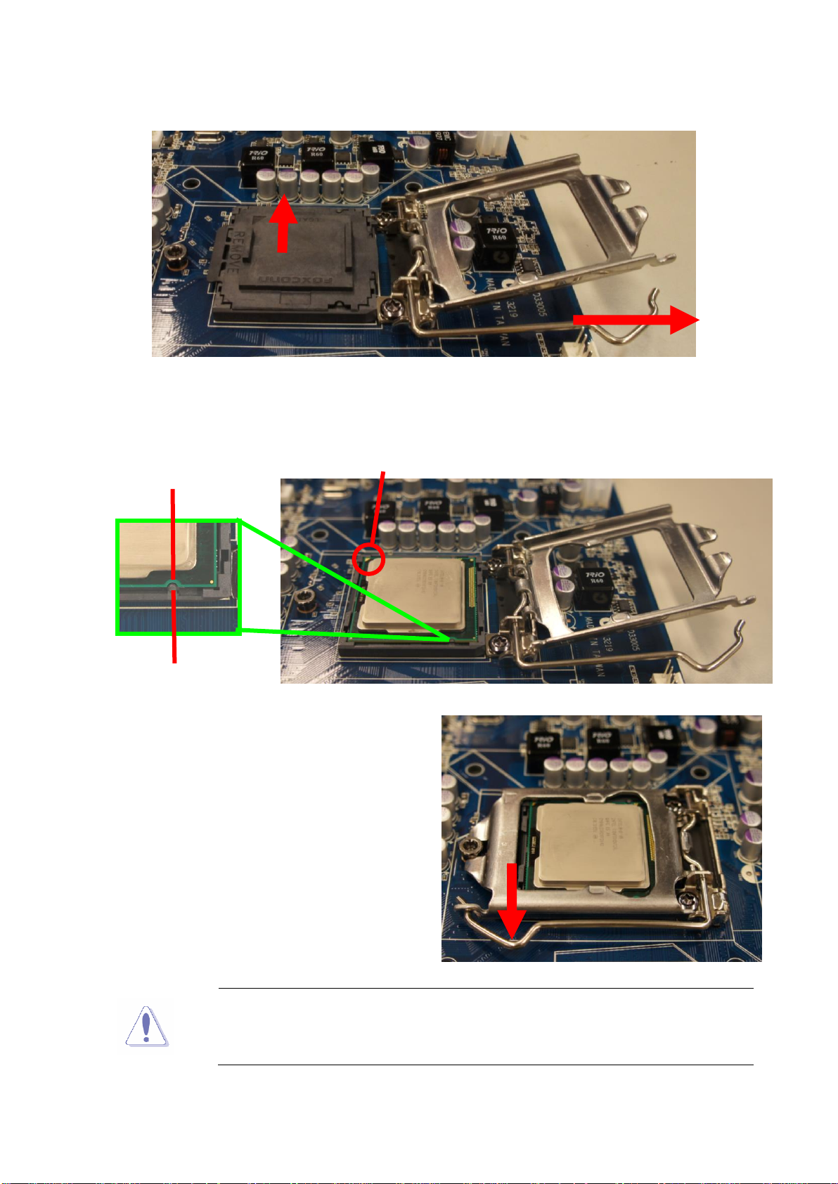
5. Pull back the load lever , then push the load
lever (A) until it snaps into the retention tab.
The CPU fits in only one correct orientation. DO NOT force the CPU
into the socket to prevent bending the connectors on the socket and
damaging the CPU!
Alignment key
CPU notch
Gold triangle
B
A
A
3. Lift the Load lever with your thumb and forefinger to around 180º angle (A), then pull the
PnP cap from the CPU socket to remove (B).
4. Position the CPU over the socket, making sure that the gold triangle is on the top-left
corner of the socket then fit the socket alignment key into the CPU notch.
EAX-Q87R User’s Manual

EAX-Q87R User’s Manual
Install the motherboard to the chassis before you install the CPU
fan and heatsink assembly.
When you buy a boxed Intel® Core™ i7/ i5/ i3 LGA1150
processor, the package includes the CPU fan and heatsink
assembly. If you buy a CPU separately, make sure that you use
only Intel® certified multi‑directional heatsink and fan.
Your Intel® Core™ i7/ i5/ i3 LGA1150 processor LGA1150
heatsink and fan assembly comes in a push-pin design and
requires no tool to install.
If you purchased a separate CPU heatsink and fan assembly, make
sure that you have properly applied Thermal Interface Material to the
CPU heatsink or CPU before you install the heatsink and fan
assembly.
Orient the heatsink and fan assembly such that the CPU fan cable is
closest to the CPU fan connector.
Make sure each fastener is oriented as shown, with the narrow
groove directed outward.
Motherboard hole
Fastener
Narrow end of
the groove
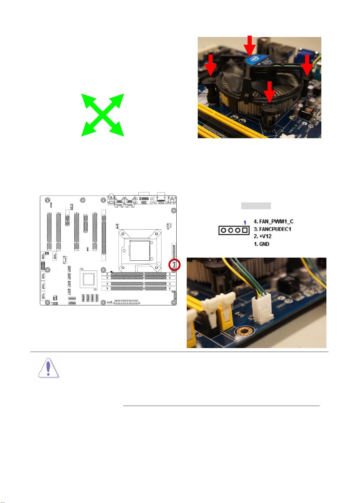
2.4.2 Installing the CPU Heatsink and Fan
Intel® Core™ i7/ i5/ i3 LGA1150 processor requires a specially designed heatsink and fan
assembly to ensure optimum thermal condition and performance.
To install the CPU heatsink and fan:
1. Place the heatsink on top of the installed CPU, making sure that the four fasteners match
the holes on the motherboard.
22 EAX-Q87R User’s Manual
EAX-Q87R User’s Manual
23
2. Push down two fasteners at a time in a
diagonal sequence to secure the heatsink and fan
assembly in place.
CPU FAN1
Do not forget to connect the fan cables to the fan
connectors. Insufficient air flow inside the system may
damage the motherboard components.
These are not jumpers! DO NOT place jumper caps on the
fan connectors.
A A B
B
A
B
A
B
3. Connect the CPU fan cable to the connector on the motherboard labeled CPU_FAN1.
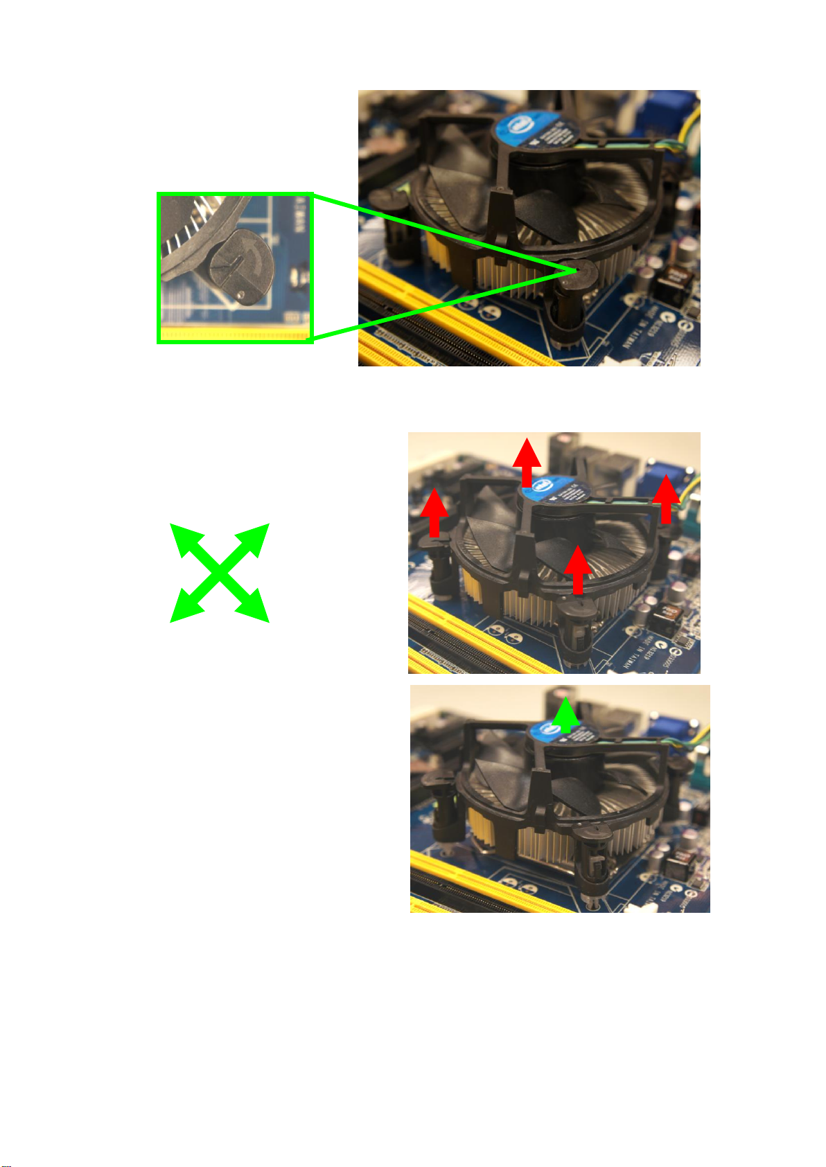
2.4.3 Uninstalling the CPU Heatsink and Fan
To uninstall the CPU heatsink and fan:
1. Disconnect the CPU fan cable from the connector on the motherboard.
2. Rotate each fastener counterclockwise
EAX-Q87R User’s Manual
EAX-Q87R User’s Manual
4. Carefully remove the heatsink and fan
assembly from the motherboard.
A B A
B
A A B
B
3. Pull up two fasteners at a time in a diagonal sequence to disengage the heatsink and fan
assembly from the motherboard.
24 EAX-Q87R User’s Manual
EAX-Q87R User’s Manual
25
5. Rotate each fastener clockwise to
ensure correct orientation when
reinstalling.
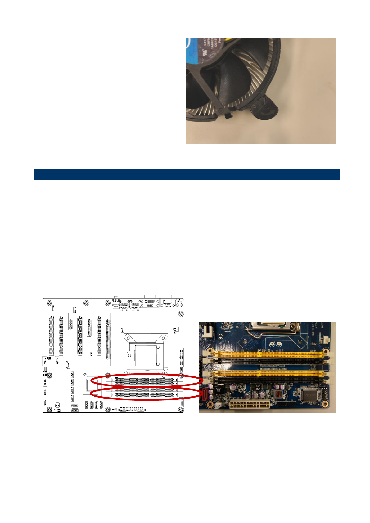
240-Pin DDR3 DIMM sockets
2.5 System Memory
2.5.1 Overview
The motherboard comes with four 240-pin Double Data Rate 3 (DDR3) Dual Inline Memory
Modules (DIMM) sockets.
A DDR3 module has the same physical dimensions as a DDR DIMM but has a 240-pin
footprint compared to the 240-pin DDR2 DIMM. DDR3 DIMMs are notched differently to
prevent installation on a DDR2 DIMM socket. The following figure illustrates the location of
the sockets:
EAX-Q87R User’s Manual

EAX-Q87R User’s Manual
Channel
Socket
Channel A
DIMMA1
DIMMA2
Channel B
DIMMB1
DIMMB2
IF you installed four 1GB memory modules, the system may detect
less than 3GB of total memory because of address space allocation
for other critical functions. This limitation applies to Windows XP
32-bit version operating system since it does not support PAE
(Physical Address Extension) mode.
IF you install Windows XP 32-bit version operating system, we
recommend that you install less than 3GB of total memory.
For dual-channel configuration, the total size of memory module(s)
installed per channel must be the same for better performance
(DIMMA1 +DIMMA2=DIMMB1+DIMMB2).
When using one DDR3 DIMM module, install into DIMMB1 slot only.
When using two DDR3 DIMM modules, install into DIMMA1 and
DIMMB1 slots only.
Always install DIMMs with the same CAS latency. For optimum
compatibility, it is recommended that you obtain memory modules
from the same vendor. Refer to the memory Qualified Vendors List
on the next page for details.
Due to CPU limitation, DIMM modules with 128 Mb memory chips or
double-sided x16 memory chips are not supported in this
motherboard.
2.5.2 Memory Configurations
You may install 1 GB, 2 GB, 4 GB & 8GB unbuffered ECC or non-ECC DDR3 DIMMs into the
DIMM sockets using the memory configurations in this section.
2.5.3 Installing a DIMM
1. Unlock a DIMM socket by pressing the retaining clips outward.
2. Align a DIMM on the socket such that the notch on the DIMM matches the break on the
socket.
26 EAX-Q87R User’s Manual

EAX-Q87R User’s Manual
27
A DDR3 DIMM is keyed with a notch so that it fits in only one
direction. DO NOT force a DIMM into a socket to avoid damaging the
DIMM.
The DDR3 DIMM sockets do not support DDR DIMMs. DO NOT
install DDR2 DIMMs to the DDR3 DIMM socket.
Make sure to unplug the power supply before adding or removing DIMMs
or other system components. Failure to do so may cause severe damage
to both the motherboard and the components.
Locked retaining clip
Unlocked retaining clip
DDR3 DIMM notch
3. Firmly insert the DIMM into the socket until the retaining clips snap back in place and the
DIMM is properly seated.
EAX-Q87R User’s Manual

EAX-Q87R User’s Manual
1. Unlock a DIMM socket by pulling the retaining clips outward
2. Align a DIMM on the socket such that the notch on the DIMM matches the break on
the socket.
3. Firmly insert the DIMM into the socket until the retaining clips snap back in place and
the DIMM is properly seated.
1. Simultaneously press the retaining clips downward to unlock the DIMM.
2. Remove the DIMM from the socket.
Support the DIMM lightly with your fingers when pressing the retaining
clips. The DIMM might get damaged when it flips out with extra force.
Make sure to unplug the power cord before adding or removing
expansion cards. Failure to do so may cause you physical injury and
damage motherboard components.
Unlocked retaining clip
2.5.4 Removing a DIMM
2.6 Expansion Card
In the future, you may need to install expansion cards. The following sub-sections describe
the slots and the expansion cards that they support.
28 EAX-Q87R User’s Manual

EAX-Q87R User’s Manual
29
2.6.3 PCI Express x16 slot
This motherboard supports one PCI Express x16 slot that complies with the PCI Express
specifications. The following figure shows a graphics card installed on the PCI Express x16
slot.
2.6.1 Installing an Expansion Card
1. Before installing the expansion card, read the documentation that came with it and make
the necessary hardware settings for the card.
2. Remove the system unit cover (if your motherboard is already installed in a chassis).
3. Remove the bracket opposite the slot that you intend to use. Keep the screw for later use.
4. Align the card connector with the slot and press firmly until the card is completely seated
on the slot.
5. Secure the card to the chassis with the screw you removed earlier.
6. Replace the system cover.
2.6.2 Configuring an Expansion Card
After installing the expansion card, configure it by adjusting the software settings.
1. Turn on the system and change the necessary BIOS settings, if any. See Chapter 2 for
information on BIOS setup.
2. Assign an IRQ to the card if needed. Refer to the tables on the next page.
3. Install the software drivers for the expansion card.
EAX-Q87R User’s Manual

EAX-Q87R User’s Manual
2.6.4 PCI Express x 4 slot
This motherboard supports one PCI Express x4 slot that complies with the PCI Express
specifications. The following figure shows a RAID card installed on the PCI Express x 4 slot.
2.6.5 PCI slot
This motherboard supports one PCI slot that complies with the PCI specifications. The
following figure shows a audio card installed on the PCI slot.
30 EAX-Q87R User’s Manual

31
*Default
2.7.2 ATX/AT Mode Selection (JPSON1)
Normal*
Clear CMOS
*Default
ATX MODE*
AT MODE
2.7 Setting Jumpers & Connectors
2.7.1 Clear CMOS Jumper (JCMOS1)
EAX-Q87R User’s Manual
EAX-Q87R User’s Manual

EAX-Q87R User’s Manual
* Default
RI*
+12V
+5V
* Default
RS232*
RS422
RS485
2.7.3 COM2 Ring-In/ +12V/ +5V Select (JCOMPWR1)
2.7.4 Set COM2 RS-232/422/485 Mode (JSETCOM1)
32 EAX-Q87R User’s Manual

33
EATXPWR1
2.7.5 ATX Power Connectors: EATXPWR1
EAX-Q87R User’s Manual
2.7.6 12V ATX Power Connector (ATX12V1)
EAX-Q87R User’s Manual

EAX-Q87R User’s Manual
2.7.7 Serial Port 1 Connector (COM1)
2.7.8 Serial Port 2 Connector (COM2)
34 EAX-Q87R User’s Manual

35
2.7.9 Serial Port 3~6 Connectors (COM3~6)
COM6
COM5
COM4
COM3
EAX-Q87R User’s Manual
2.7.10 LPT Port Connector (LPT1)
EAX-Q87R User’s Manual

EAX-Q87R User’s Manual
CPU_FAN1
SYS_FAN1
CHA_FAN1
2.7.11 Front Panel Connector (F_PANEL1)
2.7.12 Fan Connectors (CPU_FAN1, SYS_FAN1, CHA_FAN1)
36 EAX-Q87R User’s Manual

37
USB78
USB56
USB910
USB1112
SATA5
SATA4
SATA1
SATA6
SATA2
SATA3
2.7.13 SATA Ports (SATA1~6)
EAX-Q87R User’s Manual
2.7.14 Front USB Headers (USB56, USB78, USB910, USB1112)
EAX-Q87R User’s Manual

EAX-Q87R User’s Manual
2.7.15 Front Panel Audio Connector (FPAUD1)
2.7.16 Amplifier Connector (JAMP1)
38 EAX-Q87R User’s Manual

39
2.7.17 Digital I/O Connector (JDIO1)
EAX-Q87R User’s Manual
EAX-Q87R User’s Manual

EAX-Q87R User’s Manual
3. BIOS Setup
3.1 Introduction
The BIOS setup program allows users to modify the basic system configuration. This
chapter describes how to access the BIOS setup program and the configuration options
that may be changed.
3.2 Starting Setup
The BIOS is immediately activated when you first power on the computer. The BIOS reads
the system information contained in the NVRAM and begins checking the system and
configuring it. When it finishes, the BIOS seeks an operating system on one of the disks
and then launch and turn control over to the operating system.
While the BIOS is in control, the Setup program can be activated in one of two ways:
By pressing <Del> or <ESC> immediately after switching the system on, or
By pressing the <Del> or <ESC> key when the following message appears briefly at the
left-top of the screen during the POST (Power On Self Test).
Press <DEL> or <ESC> to enter SETUP
If the message disappears before you respond and you still wish to enter Setup, restart the
system to try again by turning it OFF then ON or pressing the "RESET" button on the
system case. You may also restart by simultaneously pressing <Ctrl>, <Alt>, and <Delete>
keys.
40 EAX-Q87R User’s Manual

EAX-Q87R User’s Manual
41
Button
Description
Select Screen
Select Item
+ -
Change Option / Field
Enter
Select
PGUP/HOME
Go to Top of Screen
PGDN/END
Go to Bottom of Screen
F1
General help, only for Status Page Setup Menu and Option Page Setup Menu
F2
Previous Values.
F3
Optimized defaults
F4
Save & Exit Setup
ESC
Exit
3.3 Using Setup
The keys in the legend bar allow you to navigate through the various setup menus
List Box
This box appears only in the opening screen. The box displays an initial list of
configurable items in the menu you selected.
Sub-menu
Note that a right pointer symbol appears to the left of certain fields. This pointer
indicates that you can display a sub-menu from this field. A sub-menu contains
additional options for a field parameter. To display a sub-menu, move the highlight to
the field and press <Enter>. The sub-menu appears. Use the legend keys to enter
values and move from field to field within a sub-menu as you would within a menu. Use
the <Esc> key to return to the main menu.
Take some time to familiarize yourself with the legend keys and their corresponding
functions. Practice navigating through the various menus and submenus. If you
accidentally make unwanted changes to any of the fields, press <F3> to load the
optimal default values. While moving around through the Setup program, note that
explanations appear in the Item Specific Help window located to the right of each menu.
This window displays the help text for the currently highlighted field.
EAX-Q87R User’s Manual

EAX-Q87R User’s Manual
3.4 BIOS Menu Screen
When you enter the BIOS, the following screen appears. The BIOS menu screen displays
the items that allow you to make changes to the system configuration. To access the menu
items, press the up/down/right/left arrow key on the keyboard until the desired item is
highlighted, then press [Enter] to open the specific menu.
42 EAX-Q87R User’s Manual

EAX-Q87R User’s Manual
43
3.4.1 Main Setup
This menu gives you an overview of the general system specifications. The BIOS
automatically detects the items in this menu. Use this menu for basic system configurations,
such as time, date etc.
BIOS Information
Displays the auto-detected BIOS information.
System Date
The date format is <Date>,<Month>,<Day>,<Year>.
System Time
The time format is <Hour>,<Minute>,<Second>.
EAX-Q87R User’s Manual

EAX-Q87R User’s Manual
Take caution when changing the settings of the Advanced menu
items. Incorrect field values can cause the system to malfunction.
3.4.2 Advanced BIOS Setup
Select the Advanced tab from the setup screen to enter the Advanced BIOS Setup screen.
You can select any of the items in the left frame of the screen, such as Chipset
configuration, to go to the sub menu for that item. You can display an Advanced BIOS
Setup option by highlighting it using the <Arrow> keys. All Advanced BIOS Setup options
are described in this section. The Advanced BIOS Setup screen is shown below. The sub
menus are described on the following pages.
44 EAX-Q87R User’s Manual

EAX-Q87R User’s Manual
45
3.4.2.1 PCI Subsystem Setting
The PCI PnP menu items allow you to change the advanced settings for PCI/PnP devices.
The menu includes setting IRQ and DMA channel resources for either PCI/PnP or legacy
ISA devices, and setting the memory size block for legacy ISA devices.
PCI Bus Driver Version
Displays the information of PCI Bus Driver Version
PCI Latency Timer [32 PCI Bus Clocks]
Configuration options: [32 PCI Bus Clocks] ~[248 PCI Bus Clocks]
EAX-Q87R User’s Manual

EAX-Q87R User’s Manual
3.4.2.2 ACPI Settings
ACPI Sleep State [S3 (suspend to RAM )]
Select the highest ACPI sleep state the system will enter the SUSPEND button is press.
Configuration options: [Suspend Disable] [S3 (suspend to RAM )]
S3 Video Repost [Disable]
Allows you to determine whether to invoke VGA BIOS POST on S3/STR resume.
Configuration options: [Disabled] [Enabled]
PCI/PCIE Wake from S5 [Disable]
Wake On Ring Control [Disable]
Resume On RTC Alarm [Disable]
Enable or disable system wake on alarm even. When enabled, system will wake upon the
hr/min/sec specified.
Configuration options: [Disabled] [Enabled]
Deep S5 Support [Disable]
Restore AC Power Loss [Power Off]
Specify what state to go to when power is re-applied after a power failure(G3 state).
Configuration options: [Power Off] [Power On] [Last State]
46 EAX-Q87R User’s Manual

47
3.4.2.2.1 WatchDog Configuration
EAX-Q87R User’s Manual
WatchDog Count Mode [Second(s) Mode]
Configuration options: [Second(s) Mode] [Minute(s) Mode]
WatchDog TimeOut Value [0]
Timer will start to count from end of POST. 00 – Timeout Disabled.
EAX-Q87R User’s Manual

EAX-Q87R User’s Manual
It depends on each CPU type.
3.4.2.3 CPU configuration
CPU configuration
Displays the CPU information
Active Processor Cores [All]
Select the numbers of cores in each processor package.
Configuration options: [All] [1] [2] [3] [4] [5] [6] [7]
Intel Virtualization Technology [Enabled]
When enable, a VMM can utilize the additional hardware capabilities provided by
Vanderpool Technology.
Configuration options: [Disabled] [Enabled]
48 EAX-Q87R User’s Manual

EAX-Q87R User’s Manual
49
EIST[Enabled]
Enable or disable speed step.
Configuration options: [Disabled] [Enabled]
Turbo Mode[Enabled]
Configuration options: [Disabled] [Enabled]
Enhanced C1 States[Enabled]
Configuration options: [Disabled] [Enabled]
CPU C3 Report [Enabled]
Use this to enable or disable CPU C3 report to OS.
Configuration options: [Disabled] [Enabled]
CPU C6 Report [Disabled]
Use this to enable or disable CPU C6 report to OS.
Configuration options: [Disabled] [Enabled]
EAX-Q87R User’s Manual

EAX-Q87R User’s Manual
CPU C7 Report [Disabled]
Use this to enable or disable CPU C7 report to OS.
Configuration options: [Disabled] [CPU C7][CPU C7s]
3.4.2.4 SATA Configuration
Serial-ATA Controller(s) [Enabled]
Enabled/Disabled Serial-ATA Controller 0
Configuration options: [Disabled] [Enabled]
SATA Mode [IDE]
Support IDE, AHCI or RAID mode
Configuration options: [IDE][AHCI][RAID]
SATA Controller Speed [Default]
Choose SATA controller speed
50 EAX-Q87R User’s Manual

51
3.4.2.5 PCH-FW Configuration
EAX-Q87R User’s Manual
Firmware Update Configuration
Me FW Image Re-Flash [Disabled]
Enable/Disable Me FW Image Re-Flash function
Configuration options: [Disabled][Enabled]
EAX-Q87R User’s Manual

EAX-Q87R User’s Manual
3.4.2.6 AMT Configuration
Intel AMT [Enabled]
Configuration options: [Disabled] [Enabled]
Un-Configure ME [Disabled]
Configuration options: [Disabled] [Enabled]
52 EAX-Q87R User’s Manual

53
3.4.2.7 USB Configuration
USB Configuration Parameters
EAX-Q87R User’s Manual
USB Device
Display how many devices are connected.
Legacy USB Support [Enabled]
Enables Legacy USB support. AUTO option disables legacy support if no USB devices are
connected. DISABLE option will keep USB devices available only for EFI applications.
Configuration options: [Enabled] [Disabled][Auto]
EAX-Q87R User’s Manual

EAX-Q87R User’s Manual
3.4.2.8 Super IO Configuration
System Super IO Chip Parameters.
Super IO Configuration
Super IO Chip [NCT6776F]
54 EAX-Q87R User’s Manual

55
3.4.2.8.1 Serial Port 1 configuration
Set Parameters of Serial Port 1
EAX-Q87R User’s Manual
Serial Port 1 Configuration
Serial Port [Enable]
Enable or Disable Serial Port.
Configuration options: [Disabled] [Enabled]
Device Setting [IO=3F8h; IRQ=4]
Change Setting[Auto]
Select an optimal setting for Super IO device.
Configuration options: [Auto] [IO=3F8h; IRQ=4] [IO=3F8h; IRQ=3, 4, 5, 6, 7, 9. 10, 11, 12]
[IO=2F8h; IRQ=3, 4, 5, 6, 7, 9. 10, 11, 12] [IO=3E8h; IRQ=3, 4, 5, 6, 7, 9. 10, 11, 12]
[IO=2E8h; IRQ=3, 4, 5, 6, 7, 9. 10, 11, 12]
EAX-Q87R User’s Manual

EAX-Q87R User’s Manual
3.4.2.8.2 Serial Port 2 configuration
Set Parameters of Serial Port 2
Serial Port 2 Configuration
Serial Port [Enable]
Enable or Disable Serial Port.
Configuration options: [Disabled] [Enabled]
Device Setting [IO=2F8h; IRQ=3]
Change Setting[Auto]
Select an optimal setting for Super IO device.
Configuration options: [Auto] [IO=2F8h; IRQ=3] [IO=3F8h; IRQ=3, 4, 5, 6, 7, 9. 10, 11, 12]
[IO=2F8h; IRQ=3, 4, 5, 6, 7, 9. 10, 11, 12] [IO=3E8h; IRQ=3, 4, 5, 6, 7, 9. 10, 11, 12]
[IO=2E8h; IRQ=3, 4, 5, 6, 7, 9. 10, 11, 12]
RS485 Auto Flow Control Function [Disabled]
56 EAX-Q87R User’s Manual

57
3.4.2.8.3 Serial Port 3 configuration
Set Parameters of Serial Port 3
EAX-Q87R User’s Manual
Serial Port 3 Configuration
Serial Port [Enable]
Enable or Disable Serial Port.
Configuration options: [Disabled] [Enabled]
Device Setting [IO=3E8h; IRQ=5]
Change Setting[Auto]
Select an optimal setting for Super IO device.
Configuration options: [Auto] [IO=3E8h; IRQ=5] [IO=3F8h; IRQ=5, 10] [IO=2F8h; IRQ=5, 10]
[IO=3E8h; IRQ=5, 10] [IO=2E8h; IRQ=5, 10]
EAX-Q87R User’s Manual

EAX-Q87R User’s Manual
3.4.2.8.4 Serial Port 4 configuration
Set Parameters of Serial Port 4
Serial Port 4 Configuration
Serial Port [Enable]
Enable or Disable Serial Port.
Configuration options: [Disabled] [Enabled]
Device Setting [IO=2E8h; IRQ=10]
Change Setting[Auto]
Select an optimal setting for Super IO device.
Configuration options: [Auto] [IO=2E8h; IRQ=5] [IO=3F8h; IRQ=5, 10] [IO=2F8h; IRQ=5, 10]
[IO=3E8h; IRQ=5, 10] [IO=2E8h; IRQ=5, 10]
58 EAX-Q87R User’s Manual

59
3.4.2.8.5 Serial Port 5 configuration
Set Parameters of Serial Port 5
EAX-Q87R User’s Manual
Serial Port 5 Configuration
Serial Port [Enable]
Enable or Disable Serial Port.
Configuration options: [Disabled] [Enabled]
Device Setting [IO=2E0h; IRQ=10]
Change Setting[Auto]
Select an optimal setting for Super IO device.
Configuration options: [Auto] [IO=2E0h; IRQ=10] [IO=3F8h; IRQ=5, 10] [IO=2F8h; IRQ=5,
10] [IO=3E8h; IRQ=5, 10] [IO=2E8h; IRQ=5, 10] [IO=2E0h; IRQ=5, 10] [IO=2F0h; IRQ=5,
10]
EAX-Q87R User’s Manual

EAX-Q87R User’s Manual
3.4.2.8.6 Serial Port 6 configuration
Set Parameters of Serial Port 6
Serial Port 6 Configuration
Serial Port [Enable]
Enable or Disable Serial Port.
Configuration options: [Disabled] [Enabled]
Device Setting [IO=2F0h; IRQ=10]
Change Setting[Auto]
Select an optimal setting for Super IO device.
Configuration options: [Auto] [IO=2F0h; IRQ=10] [IO=3F8h; IRQ=5, 10] [IO=2F8h; IRQ=5,
10] [IO=3E8h; IRQ=5, 10] [IO=2E8h; IRQ=5, 10] [IO=2E0h; IRQ=5, 10] [IO=2F0h; IRQ=5,
10]
60 EAX-Q87R User’s Manual

61
3.4.2.8.7 Parallel Port Configuration
EAX-Q87R User’s Manual
Parallel Port [Enable]
Use this item to enable or disable the onboard parallel port.
Configuration options: [Disabled] [Enabled]
Change Settings [Auto]
Use this item to select an optional setting for Super IO device.
Configuration Options : [Auto]
[IO=378h; IRQ=7]
[IO=378h; IRQ=6,7,9,11,12]
[IO=278h; IRQ=6,7,9,11,12]
EAX-Q87R User’s Manual

EAX-Q87R User’s Manual
Device Mode [STD Printer Mode]
Use this item to change the Printer Port mode.
Configuration Options : [STD Printer Mode]
[SPP Mode]
[EPP-1.9 and SPP Mode]
[EPP-1.7 and SPP Mode]
[ECP Mode]
[ECP Mode and EPP-1.9 Mode]
[ECP Mode and EPP-1.7 Mode]
62 EAX-Q87R User’s Manual

63
3.4.2.9 Hardware Monitor
PC Health Status
Display system health status
EAX-Q87R User’s Manual
EAX-Q87R User’s Manual

EAX-Q87R User’s Manual
3.4.2.9.1 Smart Fan
Smart Fan Function [Enable]
Configuration options: [Disabled] [Enabled]
64 EAX-Q87R User’s Manual

65
3.4.2.9.2 Smart Fan Mode Configruation
Smart Fan Mode configuration
EAX-Q87R User’s Manual
System Fan Mode [Manual Mode]
Select system Fan mode
Configuration options: [Manual Mode] [Thermal Cruise Mode]
CPU Fan Mode [Manual Mode]
Select CPU Fan mode
Configuration options: [Manual Mode] [Thermal Cruise Mode]
CHA Fan Mode [Manual Mode]
Select CHA Fan mode
Configuration options: [Manual Mode] [Thermal Cruise Mode]
EAX-Q87R User’s Manual

EAX-Q87R User’s Manual
3.4.2.10 Option ROM Policy
Launch Storage OpROM policy
Controls the execution of UEFI and Legacy Storage OpROM
Configuration options: [Do not launch] [UEFI only][Legacy only]
Other PCI Device ROM priority
Configuration options: [UEFI OpROM] [Legacy OpROM]
66 EAX-Q87R User’s Manual

67
3.4.2.11 Intel RC Driver Version Detail
EAX-Q87R User’s Manual
EAX-Q87R User’s Manual

EAX-Q87R User’s Manual
3.4.3 Chipset
68 EAX-Q87R User’s Manual

69
3.4.3.1 PCH-IO Configuration
PCH-IO Configuration
EAX-Q87R User’s Manual
LAN1 Controller [Enable]
Enable/Disable LAN1 Controller
Configuration options: [Disabled] [Enabled]
LAN1 Option-ROM [Disable]
Enable/Disable LAN1 boot option for legacy network devices.
Configuration options: [Disabled] [Enabled]
Wake on LAN1 from S5 [Disable]
LAN2 Controller [Enable]
Enable/Disable LAN1 Controller
Configuration options: [Disabled] [Enabled]
LAN2 Option-ROM [Disable]
Enable/Disable LAN2 boot option for legacy network devices.
Configuration options: [Disabled] [Enabled]
EAX-Q87R User’s Manual

EAX-Q87R User’s Manual
3.4.3.1.1 PCI Express Configuration
70 EAX-Q87R User’s Manual

EAX-Q87R User’s Manual
71
ASPM Support [Disabled]
Configuration options:[Disabled][L0s] [L1] [L0sL1][Auto]
PCIe Speed [Auto]
Configuration options:[Autio][Gen1] [Gen2]
Detect Non-Compliance Device [Disabled]
Configuration options:[Disabled][Enabled]
EAX-Q87R User’s Manual

EAX-Q87R User’s Manual
ASPM Support [Disabled]
Configuration options:[Disabled][L0s] [L1] [L0sL1][Auto]
PCIe Speed [Auto]
Configuration options:[Autio][Gen1] [Gen2]
Detect Non-Compliance Device [Disabled]
Configuration options:[Disabled][Enabled]
72 EAX-Q87R User’s Manual

73
3.4.3.1.2 USB Configuration
EAX-Q87R User’s Manual
USB Precondition [Disabled]
XHCI Mode [Smart Auto]
Configuration options:[Smart Auto][Auto][Enabled][Disabled][Manual]
USB ports per-port disable control [Disable]
Configuration options: [Disabled] [Enabled]
EAX-Q87R User’s Manual

EAX-Q87R User’s Manual
3.4.3.1.3 PCH Azalla Configuration
Azallia [Enabled]
Configuration options:[Enabled][Disabled]
Audio Amplifier [15.3 dB]
Configuration options:[15.3 dB] [21.2 dB] [27.2 dB] [31.8 dB] [Disabled]
74 EAX-Q87R User’s Manual

75
3.4.3.2 System Agent (SA) Configuration
EAX-Q87R User’s Manual
VT-d [Enabled]
Set VT-d Enable or Disable
Configuration options: [Disabled] [Enabled]
EAX-Q87R User’s Manual

EAX-Q87R User’s Manual
3.4.3.2.1 Graphics Configuration
Primary Display [AUTO]
Select which of IGFX/PEG Graphics device should be Primary Display or select SG for
Switchable Gfx.
Configuration options: [AUTO][IGFX][PEG][PCIE]
Internal Graphics
Configuration options: [Auto] [Disabled][Enabled]
Aperture Size
Configuration options: [128MB] [256MB][512MB]
DVMT Pre-Allocated [32M]
Select DVMT 5.0 Pre-Allocated (Fixed) graphics memory size used by the internal
graphics device. Configuration options: [32M]~[512M]
DVMT Total Gfx Mem [256M]
Select DVMT 5.0 total graphics memory size used by the internal graphics device.
Configuration options: [128M][256M][MAX]
76 EAX-Q87R User’s Manual

77
3.4.3.2.1.1 Boot Display Control
EAX-Q87R User’s Manual
Boot Display [VBIOS Default]
Select the Video Device that will be activated during POST. This has no effect if external
graphics present. Secondary booty display selection will appear based on your selection.
VGA modes will be supported only on primary display.
Configuration options: [VBIOS Default][CRT] [Display Port] [DVI-D]
EAX-Q87R User’s Manual

EAX-Q87R User’s Manual
3.4.3.2.2 PCIe Configuration
PEG1 – Gen X [Auto]
Configure PEG0 Gen1~Gen3
Configuration options: [Auto][Gen1][Gen2][Gen3]
Run-Time C7 Allowed [Disable]
Configuration options: [Disabled][Enabled]
Enable PEG [Auto]
To enable/Disable the PEG slot.
Configuration options: [Auto][Enable][Disable]
Detect Non-Compliance Device [Disable]
Program PCIe ASPM after OpROM [Disable]
PEG1- ASPM [Disabled]
Control ASPM support for the PEG Device. This has no effect if PEG is not the currently
78 EAX-Q87R User’s Manual

EAX-Q87R User’s Manual
79
active device.
Configuration options: [Disabled] [Auto] [ASPM L0s] [ASPM L1] [ASPM L0sL1]
3.4.3.2.3 Memory Information
Memory Information
Display Memory Information
EAX-Q87R User’s Manual

EAX-Q87R User’s Manual
3.4.4 Boot
Boot Configuration
Setup Prompt Timeout [1]
Number of seconds to wait for setup activation key. 65535(0xFFFF) means indefinite
waiting.
Bootup NumLock State [On]
Select the keyboard NumLock state
Configuration options: [On] [Off]
Quiet Boot [Disable]
Configuration options:[Enable][Disable]
Fast Boot [Disable]
Configuration options:[Enable][Disable]
Boot mode select [LEGACY]
Configuration options:[UEFI][ LEGACY]
80 EAX-Q87R User’s Manual

EAX-Q87R User’s Manual
81
FIXED BOOT ORDER Priorities
These items specify the boot device priority sequence from the all bootable device.
3.4.5 Security
Administrator Password
Set setup Administrator Password
User Password
Set User Password
EAX-Q87R User’s Manual

EAX-Q87R User’s Manual
3.4.6 Save & Exit
Save changes and Exit
Exit system setup after saving the changes.
Discard changes and Exit
Exit system setup without saving the changes.
Save changes and Reset
Reset system after saving the changes.
Discard changes and Reset
Reset system without saving the changes.
Restore Defaults
Restore/Load default values for all the setup option.
82 EAX-Q87R User’s Manual
 Loading...