


ASM-CDV
Fanless Intel® Atom™ D2550 1.86GHz CPU
Ultra Slim PC with Intel® NM10 Express Chipset
Quick Reference Guide
2nd Ed – 9 August 2013
Copyright Notice
Copyright© 2013 Avalue Technology Inc., ALL RIGHTS RESERVED.
Part No. E20175820A2R

ASM-CDV
FCC Statement
Notice
Copyright Notice
Trademark Acknowledgement
Disclaimer
THIS DEVICE COMPLIES WITH PART 15 FCC RULES. OPERATION IS
SUBJECT TO THE FOLLOWING TWO CONDITIONS:
(1) THIS DEVICE MAY NOT CAUSE HARMFUL INTERFERENCE.
(2) THIS DEVICE MUST ACCEPT ANY INTERFERENCE RECEIVED INCLUDING
INTERFERENCE THAT MAY CAUSE UNDESIRED OPERATION.
THIS EQUIPMENT HAS BEEN TESTED AND FOUND TO COMPLY WITH THE LIMITS
FOR A CLASS "A" DIGITAL DEVICE, PURSUANT TO PART 15 OF THE FCC RULES.
THESE LIMITS ARE DESIGNED TO PROVIDE REASONABLE PROTECTION AGAINST
HARMFUL INTERFERENCE WHEN THE EQUIPMENT IS OPERATED IN A
COMMERCIAL ENVIRONMENT. THIS EQUIPMENT GENERATES, USES, AND CAN
RADIATE RADIO FREQUENCY ENERGY AND, IF NOT INSTALLED AND USED IN
ACCORDANCE WITH THE INSTRUCTION MANUAL, MAY CAUSE HARMFUL
INTERFERENCE TO RADIO COMMUNICATIONS.
OPERATION OF THIS EQUIPMENT IN A RESIDENTIAL AREA IS LIKELY TO CAUSE
HARMFUL INTERFERENCE IN WHICH CASE THE USER WILL BE REQUIRED TO
CORRECT THE INTERFERENCE AT HIS OWN EXPENSE.
This guide is designed for experienced users to setup the system within the shortest time.
For detailed information, please always refer to the electronic user's manual.
Copyright 2013 Avalue Technology Inc., ALL RIGHTS RESERVED.
No part of this document may be reproduced, copied, translated, or transmitted in any form
or by any means, electronic or mechanical, for any purpose, without the prior written
permission of the original manufacturer.
Brand and product names are trademarks or registered trademarks of their respective
owners.
Avalue Technology Inc. reserves the right to make changes, without notice, to any product,
including circuits and/or software described or contained in this manual in order to improve
design and/or performance. Avalue Technology assumes no responsibility or liability for the
use of the described product(s), conveys no license or title under any patent, copyright, or
masks work rights to these products, and makes no representations or warranties that
2 ASM-CDV Quick Reference Guide

Quick Reference Guide
3
Life Support Policy
A Message to the Customer
these products are free from patent, copyright, or mask work right infringement, unless
otherwise specified. Applications that are described in this manual are for illustration
purposes only. Avalue Technology Inc. makes no representation or warranty that such
application will be suitable for the specified use without further testing or modification.
Avalue Technology’s PRODUCTS ARE NOT FOR USE AS CRITICAL COMPONENTS IN
LIFE SUPPORT DEVICES OR SYSTEMS WITHOUT THE PRIOR WRITTEN APPROVAL
OF Avalue Technology Inc.
As used herein:
1. Life support devices or systems are devices or systems which, (a) are intended for
surgical implant into body, or (b) support or sustain life and whose failure to perform,
when properly used in accordance with instructions for use provided in the labeling, can
be reasonably expected to result in significant injury to the user.
2. A critical component is any component of a life support device or system whose failure
to perform can be reasonably expected to cause the failure of the life support device or
system, or to affect its safety or effectiveness.
Avalue Customer Services
Each and every Avalue’s product is built to the most exacting specifications to ensure
reliable performance in the harsh and demanding conditions typical of industrial
environments. Whether your new Avalue device is destined for the laboratory or the factory
floor, you can be assured that your product will provide the reliability and ease of operation
for which the name Avalue has come to be known.
Your satisfaction is our primary concern. Here is a guide to Avalue’s customer services. To
ensure you get the full benefit of our services, please follow the instructions below carefully.
Technical Support
We want you to get the maximum performance from your products. So if you run into
technical difficulties, we are here to help. For the most frequently asked questions, you can
easily find answers in your product documentation. These answers are normally a lot more
detailed than the ones we can give over the phone. So please consult the user’s manual
first.
To receive the latest version of the user’s manual; please visit our Web site at:
http://www.avalue.com.tw/
ASM-CDV Quick Reference Guide
ASM-CDV
1. Getting Started
1.1 Safety Precautions
Warning!
Always completely disconnect the power cord from your
chassis whenever you work with the hardware. Do not
make connections while the power is on. Sensitive
electronic components can be damaged by sudden power
surges. Only experienced electronics personnel should
open the PC chassis.
Caution!
Always ground yourself to remove any static charge before
touching the CPU card. Modern electronic devices are very
sensitive to static electric charges. As a safety precaution,
use a grounding wrist strap at all times. Place all electronic
components in a static-dissipative surface or static-shielded
bag when they are not in the chassis.
1.2 Packing List
1 x ASM-CDV (with EBM-CDV inside)
1 x Quick Reference Guide
1 x DVD-ROM contains the followings:
— User’s Manual (this manual in PDF file)
— Ethernet driver and utilities
— VGA drivers and utilities
— Audio drivers and utilities
— Chipset drivers and utilities.
1 x packing set includes the followings:
— 1 x AC to DC Adapter
— 1 x Power cord
— 1 x Screw kit for 2.5” HDD/SSD fixing
4 ASM-CDV Quick Reference Guide

5
System
Board
EBM-CDV
CPU
Onboard Intel® Atom™ D2550 1.86GHz CPU
BIOS
AMI 16Mbit SPI BIOS
System Chipset
Intel® NM10 Express Chipset
System Memory
One 204-pin SODIMM Supports Up to 4GB DDR3 1066MHz SDRAM
SSD
One CompactFlash Type I/II Socket
Audio
Realtek ALC892 Support 5.1-CH Audio
Ethernet
Dual Intel® 82574L Gigabit Ethernet
System Indicators
4 LED Indicators Show Power and HDD Status
Drive Bay
Mounting Kit for One 2.5” SATA HDD/ SSD (Hidden)
Expansion Interface
1 x Mini PCIe Slot (mSATA Supported)
External I/O
COM
2 x RS-232 (COM2 RS-232/422/485 Setting by JP & SW)
LAN
2 x RJ-45
WiFi
1 Knockouts for Antenna Mounting
VGA
1 x VGA
HDMI
1 x HDMI
Audio
1 x Mic-in, 1 x Line-in, 1 x Line-out
USB
4 x USB 2.0 (Rear 2; Front 2)
Power Supply Unit
Power Input
100 ~ 240Vac/ 50 ~ 60Hz
Power OutPut
+12Vdc/ 5A (60W)
Environmental
Power Requirement
+12Vdc ~ +26Vdc (Lockable DC Jack)
Operating Temperature
0 ~ 50°C (32 ~ 122°F)
Storage Temperature
-40 ~ 75°C (-40 ~ 167°F)
Relative Humidity
0% ~ 90% Relative Humidity, Non-condensing
Vibration Protection
With CF/ SSD: 1.5Grms, IEC 60068-2-64, Random,
5 ~ 500Hz, 30min/axis
Shock Protection
With CF/ SSD: 10G, IEC 60068-2-27, Half Sine,11ms
Dimension (W x D x H)
7.2” x 10.1” x 1.0” (182mm x 257mm x 25mm)
Weight
3.3lbs (1.5Kgs)
Mounting
VESA 100 & 75
1.3 System Specifications
Quick Reference Guide
ASM-CDV Quick Reference Guide
ASM-CDV
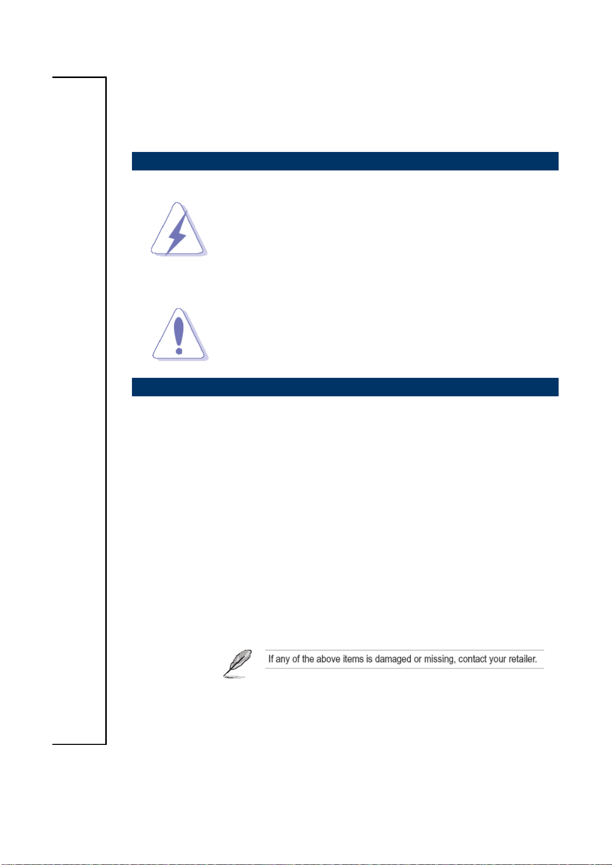
Connectors
Label
Function
Note
POWER
Power on button
LINE IN
Line-in audio jack
LINE OUT
Line-out audio jack
MIC IN
Mic-in audio jack
POWER
1.4 System Overview
1.4.1 Front View
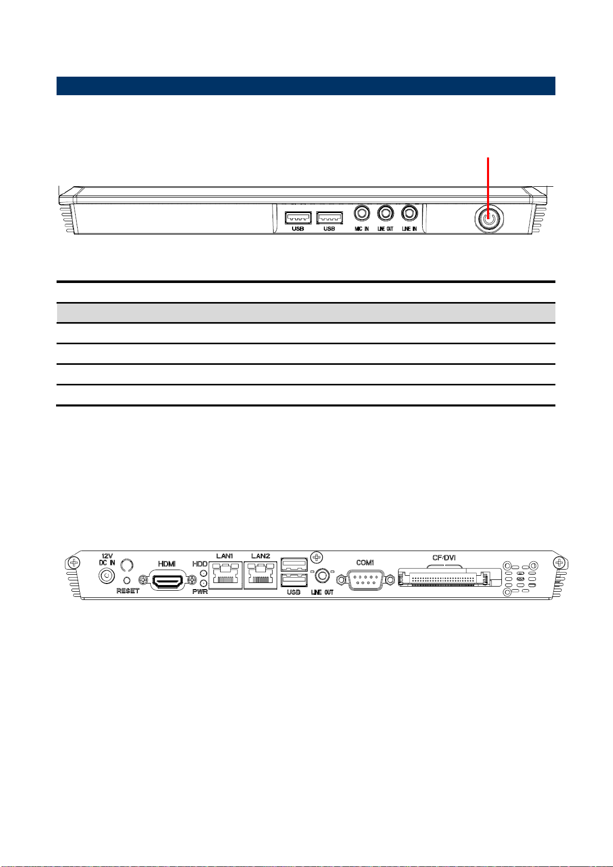
1.4.2 Rear View
6 ASM-CDV Quick Reference Guide

Quick Reference Guide
7
Connectors
Label
Function
Note
CF
CF Type I/II Socket with Ejector
COM1
Serial port 1
DB-9 male connector
COM2
Serial Port 2
DB-9 male connector
LINE OUT
Line-out audio jack
USB
2 x USB 2.0 connector
Dock USB
LAN1
2 x 10/100Base-Tx Ethernet connector
RJ-45
LAN2
2 x 10/100Base-Tx Ethernet connector
RJ-45
HDD
HDD indicator
VGA
CRT connector
DB-15 female connector
RESET
Reset button
DC-IN
DC Power-in connector
HDD
HDD indicator
HDMI
HDMI connector
PWR
System power indicator
Wi-Fi
USB Wi-Fi Module (optional)
RESET
Reset button
USB
2 x USB 2.0 connector
VGA
CRT connector
DB-15 female connector
ASM-CDV Quick Reference Guide

ASM-CDV
(Unit: mm)
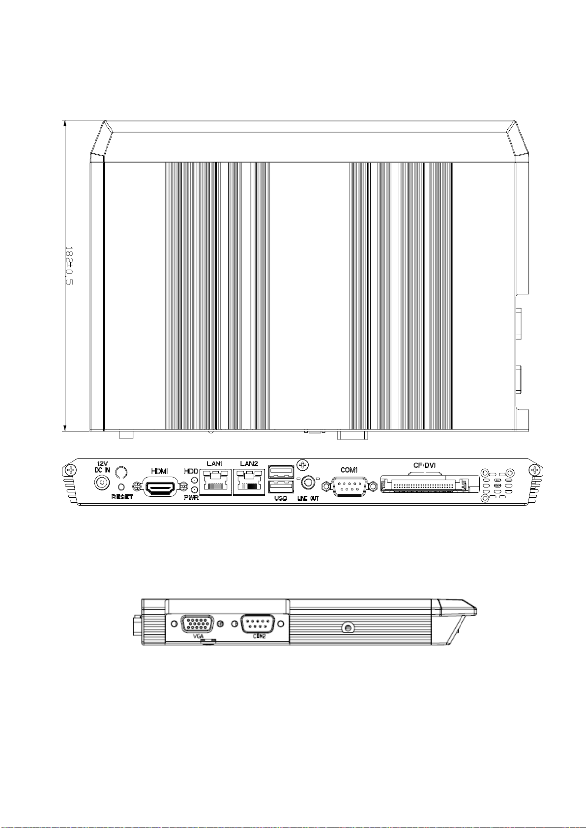
1.5 System Dimensions
1.5.1 Top and Front
8 ASM-CDV Quick Reference Guide
9
(Unit: mm)
1.5.2 Bottom and Rear
Quick Reference Guide
Side view
ASM-CDV Quick Reference Guide

ASM-CDV
2. Hardware
Configuration
2.1 Connector Setting, Driver and BIOS Installing
Please refer to EBM-CDV Quick Installation Guide or User’s Manual.
Note: If you need more information, please visit our website:
http://www.avalue.com.tw
10 ASM-CDV Quick Reference Guide

11
Step 1. Remove 10 screws from the case, and 4
screws from COM and VGA ports.
Step 2. Remove the front cover.
Step 3. Remove the top chassis.
Step 4. Install the DDR SODIMM into the memory
socket.
Step 5-1. HDD installation: Connect the HDD to
SATA connector via SATA cable, as
shown above.
Step 5-2. Place HDD and SATA cable as shown
above for a proper installation of the HDD.
2.2 Installing Hard Disk & Memory
Quick Reference Guide
ASM-CDV Quick Reference Guide

ASM-CDV
Step 5-3. Insert the HDD into the Drive Bay. Remember
to properly seat the HDD so as to match screws and
HDD holes.
Step 6. Reassemble the top chassis and
fasten with 3 screws.
Step 7. Fasten 4 screws from the bottom chassis.
Step 8. Reassemble the rear chassis and
fasten 3 screws to lock.
12 ASM-CDV Quick Reference Guide
 Loading...