

Page 1

ACP-IMX6POS
Freescale i.MX6 Cortex-A9 Dual Lite/ Quad 1GHz
User’s manual
3rd Ed – 11 March 2015
Part No. E2047IMX602R
Page 2

ACP-IMX6POS User’s Manual
FCC Statement
Notice
Copyright Notice
Trademark Acknowledgement
Disclaimer
THIS DEVICE COMPLIES WITH PART 15 FCC RULES. OPERATION IS
SUBJECT TO THE FOLLOWING TWO CONDITIONS:
(1) THIS DEVICE MAY NOT CAUSE HARMFUL INTERFERENCE.
(2) THIS DEVICE MUST ACCEPT ANY INTERFERENCE RECEIVED INCLUDING
INTERFERENCE THAT MAY CAUSE UNDESIRED OPERATION.
THIS EQUIPMENT HAS BEEN TESTED AND FOUND TO COMPLY WITH THE LIMITS
FOR A CLASS "A" DIGITAL DEVICE, PURSUANT TO PART 15 OF THE FCC RULES.
THESE LIMITS ARE DESIGNED TO PROVIDE REASONABLE PROTECTION AGAINST
HARMFUL INTERFERENCE WHEN THE EQUIPMENT IS OPERATED IN A
COMMERCIAL ENVIRONMENT. THIS EQUIPMENT GENERATES, USES, AND CAN
RADIATE RADIO FREQUENCY ENERGY AND, IF NOT INSTALLED AND USED IN
ACCORDANCE WITH THE INSTRUCTION MANUAL, MAY CAUSE HARMFUL
INTERFERENCE TO RADIO COMMUNICATIONS.
OPERATION OF THIS EQUIPMENT IN A RESIDENTIAL AREA IS LIKELY TO CAUSE
HARMFUL INTERFERENCE IN WHICH CASE THE USER WILL BE REQUIRED TO
CORRECT THE INTERFERENCE AT HIS OWN EXPENSE.
This guide is designed for experienced users to setup the system within the shortest time.
For detailed information, please always refer to the electronic user's manual.
Copyright 2015 Avalue Technology Inc., ALL RIGHTS RESERVED.
No part of this document may be reproduced, copied, translated, or transmitted in any form
or by any means, electronic or mechanical, for any purpose, without the prior written
permission of the original manufacturer.
Brand and product names are trademarks or registered trademarks of their respective
owners.
Avalue Technology Inc. reserves the right to make changes, without notice, to any product,
including circuits and/or software described or contained in this manual in order to improve
design and/or performance. Avalue Technology assumes no responsibility or liability for the
use of the described product(s), conveys no license or title under any patent, copyright, or
masks work rights to these products, and makes no representations or warranties that
these products are free from patent, copyright, or mask work right infringement, unless
2 ACP-IMX6POS User’s Manual
Page 3

ACP-IMX6POS User’s Manual
Life Support Policy
A Message to the Customer
otherwise specified. Applications that are described in this manual are for illustration
purposes only. Avalue Technology Inc. makes no representation or warranty that such
application will be suitable for the specified use without further testing or modification.
Avalue Technology’s PRODUCTS ARE NOT FOR USE AS CRITICAL COMPONENTS IN
LIFE SUPPORT DEVICES OR SYSTEMS WITHOUT THE PRIOR WRITTEN APPROVAL
OF Avalue Technology Inc.
As used herein:
1. Life support devices or systems are devices or systems which, (a) are intended for
surgical implant into body, or (b) support or sustain life and whose failure to perform,
when properly used in accordance with instructions for use provided in the labeling, can
be reasonably expected to result in significant injury to the user.
2. A critical component is any component of a life support device or system whose
failure to perform can be reasonably expected to cause the failure of the life
support device or system, or to affect its safety or effectiveness.
Avalue Customer Services
Each and every Avalue’s product is built to the most exacting specifications to ensure
reliable performance in the harsh and demanding conditions typical of industrial
environments. Whether your new Avalue device is destined for the laboratory or the factory
floor, you can be assured that your product will provide the reliability and ease of operation
for which the name Avalue has come to be known.
Your satisfaction is our primary concern. Here is a guide to Avalue’s customer services. To
ensure you get the full benefit of our services, please follow the instructions below carefully.
Technical Support
We want you to get the maximum performance from your products. So if you run into
technical difficulties, we are here to help. For the most frequently asked questions, you can
easily find answers in your product documentation. These answers are normally a lot more
detailed than the ones we can give over the phone. So please consult the user’s manual
first.
To receive the latest version of the user’s manual; please visit our Web site at:
http://www.avalue.com.tw/
ACP-IMX6POS User’s Manual 3
Page 4

ACP-IMX6POS User’s Manual
Product Warranty
Avalue warrants to you, the original purchaser, that each of its products will be free from
defects in materials and workmanship for two years from the date of purchase.
This warranty does not apply to any products which have been repaired or altered by
persons other than repair personnel authorized by Avalue, or which have been subject to
misuse, abuse, accident or improper installation. Avalue assumes no liability under the
terms of this warranty as a consequence of such events. Because of Avalue’s high
quality-control standards and rigorous testing, most of our customers never need to use our
repair service. If any of Avalue’s products is defective, it will be repaired or replaced at no
charge during the warranty period. For out-of-warranty repairs, you will be billed according
to the cost of replacement materials, service time, and freight. Please consult your dealer
for more details. If you think you have a defective product, follow these steps:
1. Collect all the information about the problem encountered. (For example,
CPU type and speed, Avalue’s products model name, hardware & BIOS
revision number, other hardware and software used, etc.) Note anything
abnormal and list any on-screen messages you get when the problem occurs.
2. Call your dealer and describe the problem. Please have your manual, product,
and any helpful information available.
3. If your product is diagnosed as defective, obtain an RMA (return material
authorization) number from your dealer. This allows us to process your good
return more quickly.
4. Carefully pack the defective product, a complete Repair and Replacement
Order Card and a photocopy proof of purchase date (such as your sales
receipt) in a shippable container. A product returned without proof of the
purchase date is not eligible for warranty service.
5. Write the RMA number visibly on the outside of the package and ship it
prepaid to your dealer.
4 ACP-IMX6POS User’s Manual
Page 5

ACP-IMX6POS User’s Manual
CONTENT
1. Getting Started ............................................................................................................ 6
1.1 Safety Precautions ......................................................................................... 6
1.2 Packing List .................................................................................................... 6
1.3 Document Amendment History ....................................................................... 7
1.4 Manual Objectives .......................................................................................... 8
1.5 System Specifications .................................................................................... 9
1.6 Architecture Overview – Block Diagram ....................................................... 11
2. Hardware Configuration ........................................................................................... 12
2.1 Product Overview ......................................................................................... 13
2.2 Jumper and Connector List .......................................................................... 14
2.3 Setting Jumpers & Connectors ..................................................................... 16
2.3.1 Boot mode selector (JBTSL1) ............................................................... 16
2.3.2 Serial port connector 3/4 (JCOM3/4) ..................................................... 17
2.3.3 USB connector 1 (JUSB1) ..................................................................... 17
2.3.4 USB connector 2 (JUSB2) ..................................................................... 18
2.3.5 LED connector (JLED1) ........................................................................ 18
2.3.6 Touch Panel connector (JTP1) .............................................................. 19
2.3.7 Speaker connector 1 (JSPK1) ............................................................... 19
2.3.8 Speaker connector 2 (JSPK2) ............................................................... 20
2.3.9 Line In, MIC connector (JMIC1) ............................................................ 20
2.3.10 LCD inverter connector (JBKLT1) ......................................................... 21
2.3.11 VGA connector (JVGA1) ....................................................................... 21
2.3.12 LVDS connector (JLVDS1) .................................................................... 22
2.3.13 Debug UART connector (JUART1) ....................................................... 23
2.3.14 Battery holder (BAT-1) .......................................................................... 23
2.3.15 I2C device connector (JI2C1) ................................................................ 24
3. Software User Guide .................................................................................................... 25
3.1 Download Android Source Code for building image file ............................... 26
3.2 Set up for building Android image file ........................................................... 26
3.3 Building up Android image file ...................................................................... 27
3.4 Use MfgTool to flash Android into onboard eMMC ....................................... 29
ACP-IMX6POS User’s Manual 5
Page 6
ACP-IMX6POS User’s Manual
1. Getting Started
1.1 Safety Precautions
Warning!
Always completely disconnect the power cord from your
chassis whenever you work with the hardware. Do not
make connections while the power is on. Sensitive
electronic components can be damaged by sudden power
surges. Only experienced electronics personnel should
open the PC chassis.
Caution!
Always ground yourself to remove any static charge before
touching the CPU card. Modern electronic devices are very
sensitive to static electric charges. As a safety precaution,
use a grounding wrist strap at all times. Place all electronic
components in a static-dissipative surface or static-shielded
bag when they are not in the chassis.
1.2 Packing List
Before you begin installing your single board, please make sure that the
following materials have been shipped:
1 x ACP-IMX6POS Module
6 ACP-IMX6POS User’s Manual
Page 7

ACP-IMX6POS User’s Manual
Revision
Date
Comment
1st
July 2014
Initial Release
2nd
November 2014
Update System Specifications
3rd
March 2015
Update Block Diagram
1.3 Document Amendment History
ACP-IMX6POS User’s Manual 7
Page 8

ACP-IMX6POS User’s Manual
1.4 Manual Objectives
This manual describes in detail the Avalue Technology ACP-IMX6POS Single Board.
We have tried to include as much information as possible but we have not duplicated
information that is provided in the standard IBM Technical References, unless it proved to
be necessary to aid in the understanding of this board.
We strongly recommend that you study this manual carefully before attempting to interface
with ACP-IMX6POS series or change the standard configurations. Whilst all the necessary
information is available in this manual we would recommend that unless you are confident,
you contact your supplier for guidance.
Please be aware that it is possible to create configurations within the CMOS RAM that
make booting impossible. If this should happen, clear the CMOS settings, (see the
description of the Jumper Settings for details).
If you have any suggestions or find any errors concerning this manual and want to inform
us of these, please contact our Customer Service department with the relevant details.
8 ACP-IMX6POS User’s Manual
Page 9
ACP-IMX6POS User’s Manual
System
CPU
Freescale i.MX6 Cortex-A9 Dual Lite/ Quad 1GHz
System Memory
Onboard Up to 1GB(Dual Lite) or 2GB(Quad) DDR3 1066/1333 SDRAM
SSD
4~8GB eMMC
G sensor
Freescale MMA8451 (Optional)
SD Card
Micro SD Socket x1
Watchdog Timer
Freescale i.MX6 Build-in
Expansion
1x Mini PCI Express slot (USB signal only)
Supported WIFI & 3.5G module
SIM card holder onboard
Micro SD Socket x1 (in system access window area)
Touch Controller
Penmount 6000
RTC
I2C RTC Intersil ISL1208IB8Z
I/O
Serial Port
4 x COM port supported ( 2 x Pin header , 2 x Edge I/O )
All Pin 9 supported 5V/12V 1A max output, selected by GPIO.
COM1 & 2: RS232/422/485 selected in GPIO, RS232 by Standard.
COM3 & 4 Ping header
USB Port
1 x dual stack USB 2.0 port
1 x USB for USB touch controller
1 x USB for mini-PCIe socket
3 x USB pin header for optional function
USB hub is SMSC USB2517
Switch
Pin header for Power Button (The first time auto power on)
Indicator Light
Front panel right side with PWR/ WIFI/ LAN
Others
1 x RJ11 connector for cash drawer
(GPO select RJ11 power supply 12V or 24V)
Display
Chipset
Freescale i.MX6
Resolution
Up to 1920 x 1080
Multiple Display
VGA + HDMI or LVDS + HDMI
VGA signal is converted by Chrontel Ch7055A (Box header)
HDMI
From Freescale i.MX6
LCD Interface
Dual channel 24bit LVDS
1.5 System Specifications
ACP-IMX6POS User’s Manual 9
Page 10
ACP-IMX6POS User’s Manual
Audio
I2S Codec
Wolfson WM8962
Audio Port
2Pin Wafer Box P=2.0m x 2 (Speaker out R & L ) (Driver per channel max 2W)
Mic
4Pin Wafer Box P=2.0m x 1(Microphone)
Ethernet
LAN Chip
1st LAN => from i.MX6 MAC, PHY is Micrel KSZ9031RNX
2nd LAN => Intel 82574L by PCIe interface
Ethernet Interface
2 x RJ45 connectors for Dual G LAN
Internal I/O
Connectors
RTC Battery
CR2032 Battery with cable
Power ON
BOX header for Power Button (The first time auto power on)
Reset
BOX header for Reset Button
Audio
2P BOX header x 2 (Speaker out R & L ) (Driver per channel max 2W)
Rear I/O Connectors
USB
USB Type A Double Deck x 1
LAN
RJ45 connector with indicate LED x 2
HDMI
HDMI connector x 1 (Vertical type)
Mini-USB
Mini-USB connector x 1
RJ11
RJ11 connector x 1 for cash drawer
COM Port
DB9 male connector x 2
DC Jack
Wide range DC 12V to 24V power input by DC Jack connector
Mechanical &
Environmental
Power Requirement
TBD
Power Type
DC 12-24V power input
Operating Temp.
0~60 degree C
Storage Temp.
-40~85 degree C
Operating
Humidity
12hrs operation dwell time at 40℃/80% Relative Humidity, Non-condensing
Size (L x W)
175 x 110mm
Weight
TBD
Note: Specifications are subject to change without notice.
10 ACP-IMX6POS User’s Manual
Page 11

ACP-IMX6POS User’s Manual
1.6 Architecture Overview – Block Diagram
The following block diagram shows the architecture and main components of
ACP-IMX6POS.
ACP-IMX6POS User’s Manual 11
Page 12

ACP-IMX6POS User’s Manual
2. Hardware
Configuration
12 ACP-IMX6POS User’s Manual
Page 13

ACP-IMX6POS User’s Manual
2.1 Product Overview
ACP-IMX6POS User’s Manual 13
Page 14
ACP-IMX6POS User’s Manual
Jumpers
Label
Function
Note
JBTSL1
Boot Mode selector
3 x 1 header, pitch 2.00mm
Connectors
Label
Function
Note
BAT-1
Battery holder
1 x 2 wafer, pitch 1.25mm
JCOM1/2
Serial port connector 1/2
D-sub 9-pin, male
JCOM3/4
Serial port connector 3/4
5 x 2 wafer, pitch 2.00 mm
JTP1
Touch Panel connector
5 x 1 header, pitch 2.54mm
JUSB3
USB connector 3
JUSB1/2
USB connector 1/2
5 x 1 wafer, pitch 2.00mm
JMUSB1
Mini USB connector for Boot/Debug
MINI USB-MAB_5P
2.2 Jumper and Connector List
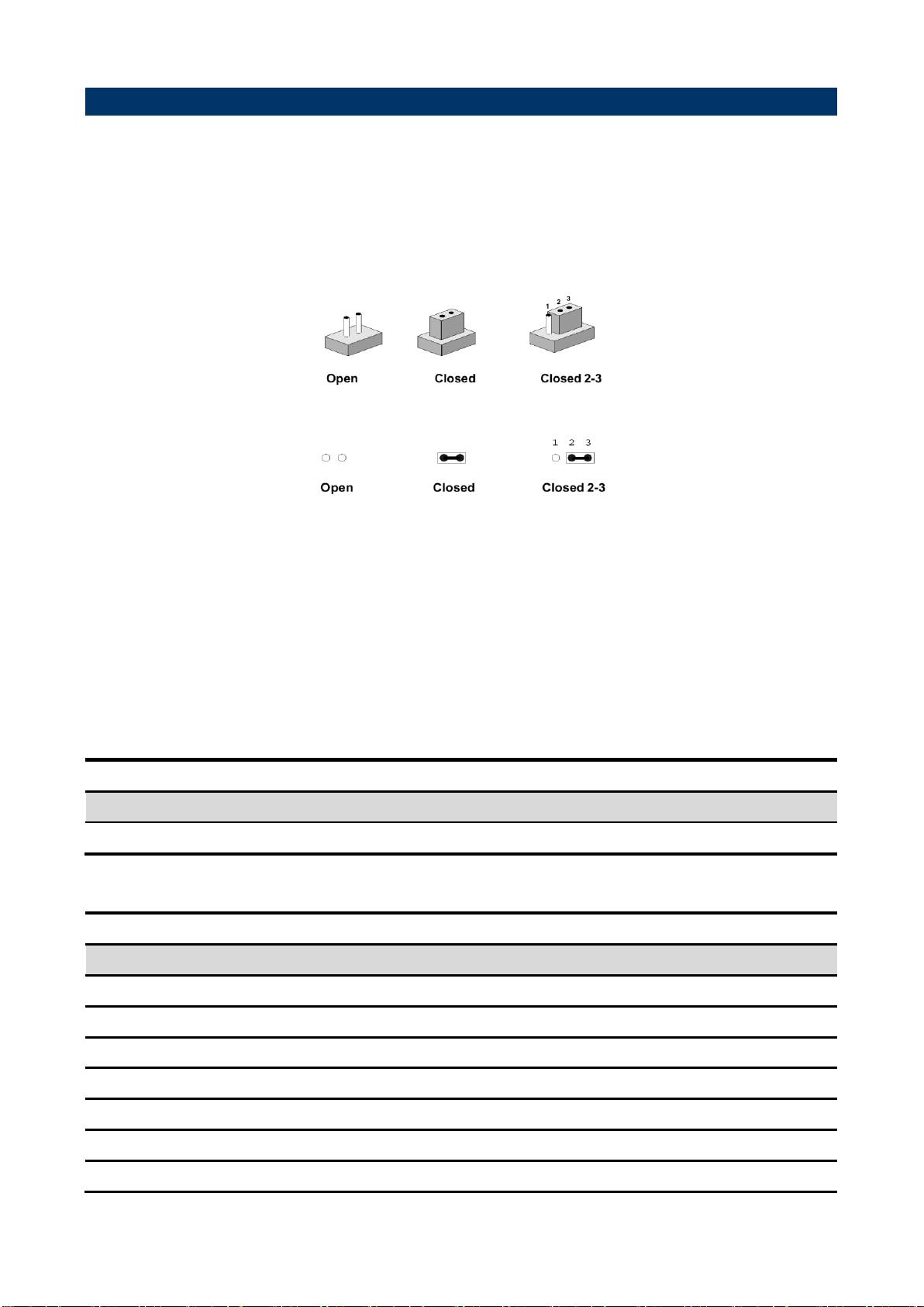
You can configure your board to match the needs of your application by setting jumpers. A
jumper is the simplest kind of electric switch.
It consists of two metal pins and a small metal clip (often protected by a plastic cover) that
slides over the pins to connect them. To “close” a jumper you connect the pins with the clip.
To “open” a jumper you remove the clip. Sometimes a jumper will have three pins, labeled 1,
2, and 3. In this case, you would connect either two pins.
The jumper settings are schematically depicted in this manual as follows:
A pair of needle-nose pliers may be helpful when working with jumpers.
Connectors on the board are linked to external devices such as hard disk drives, a
keyboard, or floppy drives. In addition, the board has a number of jumpers that allow you to
configure your system to suit your application.
If you have any doubts about the best hardware configuration for your application, contact
your local distributor or sales representative before you make any changes.
The following tables list the function of each of the board’s jumpers and connectors.
14 ACP-IMX6POS User’s Manual
Page 15

ACP-IMX6POS User’s Manual
JPWR1
DC-IN power connector
Power Jack mini din 4P
MPCIE1
Mini PCI Express connector
JCASH1
Cash Drawer
JLAN1/2
RJ-45 Ethernet connector 1/2
JVGA1
VGA connector
8 x 2 wafer, pitch 2.00mm
JLED1
LED connector
5 x 2 wafer, pitch 2.00mm
JSPK1/2
Speaker connector 1/2
2 x 1 wafer, pitch 2.00 mm
JLVDS1
LVDS connector
2 x 20 wafer, pitch 1.25 mm
SIM1
SIM Card Slot
SDCARD_9H, Push/Push Type
JMIC1
Line In, MIC connector
4 x 1 wafer, pitch 2.00mm
JBKLT1
LCD inverter connector
5 x 1 wafer, pitch 2.00mm
JMSD1
Micro SD Card Slot
JUART1
Debug UART connector
Debug message output for
users development phase only
JHDMI1
HDMI connector
JI2C1
I2C device connector
5 x 1 header, pitch 2.00mm
ACP-IMX6POS User’s Manual 15
Page 16

ACP-IMX6POS User’s Manual
Mode
Description
OTG load
eMMC boot
SD boot
2.3 Setting Jumpers & Connectors
2.3.1 Boot mode selector (JBTSL1)
16 ACP-IMX6POS User’s Manual
Page 17

ACP-IMX6POS User’s Manual
Signal
PIN
PIN
Signal
COM_DCD#
1 2 COM_RXD
COM_TXD
3 4 COM_DTR#
GND
5 6 COM_DSR#
COM_RTS#
7 8 COM_CTS#
COM_RI_A
9
10
GND
Signal
PIN
PIN
Signal
+5V
1 2 +5V
USB_NP2
3 4 USB_NP1
USB_PP2
5 6 USB_PP1
GND
7 8 GND
GND
9
10
GND
JCOM4
JCOM3
2.3.2 Serial port connector 3/4 (JCOM3/4)
2.3.3 USB connector 1 (JUSB1)
ACP-IMX6POS User’s Manual 17
Page 18

ACP-IMX6POS User’s Manual
Signal
PIN
+5V
1
USB_NP3
2
USB_PP3
3
GND
4
GND
5
Signal
PIN
PWR-LED+
1
PWR-LED-
2
WIFI-LED+
3
WIFI-LED-
4
LAN-LED+
5
LAN-LED-
6
RESET
7
8
ON/OFF
9
10
2.3.4 USB connector 2 (JUSB2)
2.3.5 LED connector (JLED1)
18 ACP-IMX6POS User’s Manual
Page 19

ACP-IMX6POS User’s Manual
Signal
PIN
UL 1 UR
2
PROBE
3
LL 4 LR
5
Signal
PIN
SPKL_N
1
SPKL_P
2
2.3.6 Touch Panel connector (JTP1)
2.3.7 Speaker connector 1 (JSPK1)
ACP-IMX6POS User’s Manual 19
Page 20

ACP-IMX6POS User’s Manual
Signal
PIN
SPKR_N
1
SPKR_P
2
Signal
PIN
MIC_DET
1
MIC_IN
2
MICBIAS
3
GND
4
2.3.8 Speaker connector 2 (JSPK2)
2.3.9 Line In, MIC connector (JMIC1)
20 ACP-IMX6POS User’s Manual
Page 21

ACP-IMX6POS User’s Manual
Signal
PIN
+12V
1
GND
2
BPEN(3.3V)
3
BKLCTL(3.3V)
4
+5V
5
Signal
PIN
PIN
Signal
+5V
1 2 VRED
GND
3 4 VGREEN
NC
5 6 VBLUE
VDATA
7 8 NC
VHS
9
10
GND
VVS
11
12
GND
VCLK
13
14
GND
GND
15
16
GND
2.3.10 LCD inverter connector (JBKLT1)
2.3.11 VGA connector (JVGA1)
ACP-IMX6POS User’s Manual 21
Page 22

ACP-IMX6POS User’s Manual
Signal
PIN
PIN
Signal
+12V
39
40
+12V
GND
37
38
GND
LVDS1_CLK_N
35
36
LVDS0_CLK_N
LVDS1_CLK_P
33
34
LVDS0_CLK_P
GND
31
32
GND
LVDS1_TX3_N
29
30
LVDS1_TX2_N
LVDS1_TX3_P
27
28
LVDS1_TX2_P
GND
25
26
GND
LVDS1_TX1_N
23
24
LVDS1_TX0_N
LVDS1_TX1_P
21
22
LVDS1_TX0_P
GND
19
20
GND
LVDS0_TX3_N
17
18
LVDS0_TX2_N
LVDS0_TX3_P
15
16
LVDS0_TX2_P
GND
13
14
GND
LVDS0_TX1_N
11
12
LVDS0_TX0_N
LVDS0_TX1_P
9
10
LVDS0_TX0_P
GND
7
8
GND
LVDS2_DDC_CLK
5 6 LVDS2_DDC_DATA
+3V
3
4
+5V
+3V
1
2
+5V
2.3.12 LVDS connector (JLVDS1)
22 ACP-IMX6POS User’s Manual
Page 23

ACP-IMX6POS User’s Manual
Signal
PIN
PIN
Signal
DBG_TX
1 2 GND
DBG_RX
3 4 GND
Signal
PIN
VBAT
1
GND
2
2.3.13 Debug UART connector (JUART1)
2.3.14 Battery holder (BAT-1)
ACP-IMX6POS User’s Manual 23
Page 24

ACP-IMX6POS User’s Manual
Signal
PIN
CS_+V3.3S
1
CS_INT#
2
CS_CLK
3
CS_DAT
4
GND
5
2.3.15 I2C device connector (JI2C1)
24 ACP-IMX6POS User’s Manual
Page 25

ACP-IMX6POS User’s Manual
3. Software User
Guide
ACP-IMX6POS User’s Manual 25
Page 26

ACP-IMX6POS User’s Manual
3.1 Download Android Source Code for building image file
Please make a folder for storing the source code first then typing the command below to get
started for the source code download.
$ sudo apt-get install git
$ git clone guest@202.55.227.57:freescale/imx6/Android.git -b 4.4.2-pos
About Password Please check with Avalue Sales or PM to get password.
3.2 Set up for building Android image file
We support to compile u-boot & Kernel on Ubuntu 12.04 (64bit version), other version of
Ubuntu is not currently supported and may have built issues.
Install host packages needed by building code. This document assumes you are using
Ubuntu. Not a requirement, but the packages may be named differently and the method of
installing them may be different.
1) Please follow up the commands below to install ”Oracle JDK6.0” first for building up
Android image file.
$ sudo apt-get install python-software-properties
$ sudo add-apt-repository ppa:webupd8team/java
$ sudo apt-get update
$ sudo apt-get install oracle-java6-installer
$ sudo update-alternatives --config java
2) Please follow up the commands below to install the necessary package for build image
file.
$ sudo apt-get install git-core gnupg flex bison gperf build-essential \
zip curl libc6-dev libncurses5-dev x11proto-core-dev gcc g++ \
libx11-dev:i386 libreadline6-dev:i386 \
libgl1-mesa-dev g++-multilib mingw32 openjdk-6-jdk tofrodos \
python-markdown libxml2-utils xsltproc zlib1g-dev:i386 \
ia32-libs u-boot-tools minicom lib32ncurses5-dev \
uuid-dev liblzo2-dev libz-dev\
26 ACP-IMX6POS User’s Manual
Page 27

ACP-IMX6POS User’s Manual
3.3 Building up Android image file
You can follow up the steps below to compile Android image file after download the source
code.
1. Please move to the folder ”Android” then start to compile image file.
2. Type the command to compile image file.
$ ./run.sh –j16
(-j number means multi jobs for more efficiant building, you can add it according to your
CPU performance of PC, e.g. mine is ”–j16” as below ).
3. You can find the finished image file(u-boot-6q.bin, u-boot-6solo.bin, system.img,
recover.img, boot.img) as below after compiling on the directory
~/Android/out/target/product/smarc.
ACP-IMX6POS User’s Manual 27
Page 28

ACP-IMX6POS User’s Manual
PS: If you would like to use Mfgtool for flashing image file into mainboard, you must put all
the files u-boot-6q.bin, u-boot-6solo.bin, system.img, recover.img, boot.img
under the path
“~\POS-Android-MfgTools\Image\POS\Android” on MFGTool folder for right
detected.
28 ACP-IMX6POS User’s Manual
Page 29

ACP-IMX6POS User’s Manual
3.4 Use MfgTool to flash Android into onboard eMMC
Manufacturing tool, a successor of ATK, provides a series of new features to power your
mass production work. The features like windows style GUI, multiple devices support,
explicit status monitoring, versatile functionalities and highly flexible architecture make it a
best choice to meet your critical timing, cost and customization requirements.
For using Mfgtool to flash image file into onboard eMMC, please follow up the steps below
1) Please turn off all pins of DIP switch (JBTSL1) as below into burning mode of Mfgtool.
2) Power on the mainboard then plug the cable from OTG socket to PC.
3) Please click “MFG-Helper” under the path
"~\POS-Android-MfgTools\Mfg-POS\”
ACP-IMX6POS User’s Manual 29
Page 30

ACP-IMX6POS User’s Manual
4) If the CPU of the mainboard is Quadcore version, please select as below, then click
“Run MFG-Tools”.
4-1) If the CPU of the mainboard is DualLite version, please select as below, then click
“Run MFG-Tools”.
5) Click “Start” to flash image file.
30 ACP-IMX6POS User’s Manual
Page 31

ACP-IMX6POS User’s Manual
6) It will show “Done” after flashing is finish, then click “Stop” and “Exit” to close the screen.
7) You can also get the information from Terminal (debug portJUART1, baud rate set as
115200) after flashing is finish
8) Power off the system and turn on pin1 of DIP switch then reboot.
ACP-IMX6POS User’s Manual 31
 Loading...