

Page 1
Wood Stove Rear Fan 2 Installation Instructions
Table of Contents
Table of Contents ...................................................................................................................................................... 1
Compatibility (Freestanding Models Only) ................................................................................................................ 1
Packing List ............................................................................................................................................................... 1
Operating Instructions ............................................................................................................................................... 1
Installation Instructions (All Except Leyden, Arbor, and 1750) .................................................................................. 1
1750 Installation Instructions ..................................................................................................................................... 4
Leyden and Arbor Installation Instructions (Rev 005 or Later – See Note Below) .................................................... 5
Compatibility (Freestanding Models Only)
• Lopi Answer • Lopi Endeavor • Lopi Liberty • Lopi Leyden
• Avalon Pendleton (745/790) • Avalon Rainier (945/990) • Avalon Olympic (1190) • Avalon Arbor
• 1250 Wood Stove • 1750 Wood Stove
99000118
Packing List
• Rear Blower
• Snap Disk Assembly
• Snap Disk Hanger
Operating Instructions
• (3) 1/4" 20 Thread Cutting Screws
• Rheostat Mounting Bracket
• (2) M8 Bolts (used for Arbor/Leyden only)
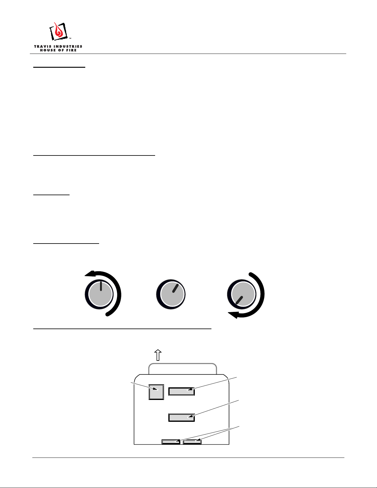
The blower will not turn on until the appliance is up to temperature. Once up to temperature, the blower will
operate at the speed determined by the position of the blower knob (see the illustration below). The blower
will shut off once the appliance cools.
OFF
Turn the knob
all the way
counterclockwise to
turn off.
HIGH
Turn the knob
clockwise from
the off position
until it clicks.
LOW
Turn the knob
all the way
clockwise to
turn to low.
Installation Instructions (All Except Leyden, Arbor, and 1750)
1. Install the stove legs or pedestal. Remove the two rear blower knock-outs underneath the base (see the
illustration below).
FRONT OF STOVE
Drop Chute Knock-Out
- found on Olympic
(1190) and Rainier (990)
only.
Outside Air Knock-Out
for standard pedestals
Ashpan Pedestal/Air Boot
Outside Air Knock-Out
Rear Blower Knock-Outs
REMOVE THESE KNOCK-OUTS
Page 1 of 5 17601791.docx - 5/2/13 © Travis Industries, Inc.
Page 2
Wood Stove Rear Fan 2 Installation Instructions
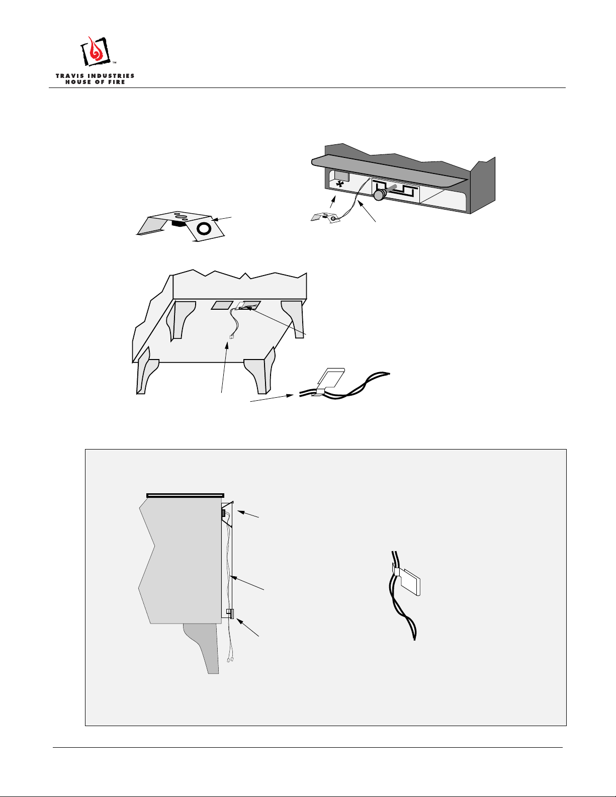
2. Install the snap disk assembly.
NOTE: For the Endeavor and Liberty follow step 2B. For all other models, follow step 2A.
2A Install the snap disk assembly into the left side convection chamber following the directions below.
2A Secure the snap disk wires in place following the directions below. Go to step 3.
NOTE: The wires must be properly secured to prevent them from
Snap Disk
Assembly
contacting the firebox and shorting out the blower circuit.
Wedge the snap disk
directly in front of the
stiffener on the left side.
Bend these legs on
the snap disk if it
does not fit tightly
Snap Disk
Wires
Wire Clip
99000118
Ashlip
Twist the wires together and feed them
through the convection chamber and
out of the knockout removed in step 1.
Slide the wire clip over the
edge of the strip of metal
between the two knock-outs.
Feed the two snap
disk wires into the
eye of the wire clip.
Then carefully
remove all slack from
the wire, making sure
not to dislodge the
snap disk. Pinch the
eye of the wire clip to
secure the wires.
2B (Liberty, Endeavor only)
Install the snap disk assembly inside the heat shield following the directions below. Secure the snap disk
wires in place following the directions below.
Hang the snap disk assembly in
the space between the stove
and rear heat shield on the left
side. Bend the legs of the
assembly to ensure a tight fit.
Snap Disk Wires
Wire Clip
Feed the two snap
disk wires into the
eye of the wire clip.
Then carefully
remove all slack from
the wire, making sure
not to dislodge the
snap disk. Pinch the
eye of the wire clip to
secure the wires.
Secure the snap disk wires in place following the directions below.
NOTE: The wires must be properly secured to prevent them from contacting the firebox an d
shorting out the blower circuit.
Page 2 of 5 17601791.docx - 5/2/13 © Travis Industries, Inc.
Page 3

Wood Stove Rear Fan 2 Installation Instructions
3. Place the blower near the bottom rear edge of the stove. Attach the quick-connects from the snap disk
assembly to the quick-connects on the blower. Push any slack wire into the blower box. Attach the
blower following the directions below.
4. Attach the rheostat and rheostat mounting bracket to the underside of the stove, behind the left front leg.
Magnets hold it in place.
Endeavor & L iberty:
a
F ee d the two wires from
the blower through this
hole before atta c h in g th e
quick -conne cts.
All Other Models:
Feed the wires
directly upwards
NOTE :
Prior to attaching the
blower, tuck all excess
wire into the area ins ide
the blowe r.
c
99000118
b
Attach the quick-connects
lea ding from the s nap dis k to the
quick-connects from the blower.
The blower attaches to the stove with the three
included screws. Us e a 3/8” socket driver or wrench.
HINT:
Attach the screws to the back of the stove prior to
attaching the blower. This will cut the threads and
ease installation.
The blower is shown in the photo below.
Plug the power cord into
a 110 V. outlet after
ins talling the blowe r.
NOTE :
P rior to a ttac h in g th e bl ow e r, tuc k a ll exce s s
wire into the area inside the blower.
Attach the rheostat box to the underside
of the stove behind the left front leg.
Magnets hold it in place.
Page 3 of 5 17601791.docx - 5/2/13 © Travis Industries, Inc.
Page 4

Wood Stove Rear Fan 2 Installation Instructions
1750 Installation Instructions
99000118
R em ove thes e two k n oc k-ou ts on
the bottom of the stov e ( u s e a
a
screwdriver to pry them out).
g
Atta c h the blow e r to th e s tove with the
thre e s cre ws inc lud e d with the blowe r.
Snap Disk
Assembly
Attach the wires from
the thermodis k to the
d
wires from the blowe r.
Place the snap disk assembly over the snap disk extender
b
(inc lu ded with the s to v e ) a nd be n d the s e ta bs to s e c ur e .
Dis connect the s e wires
Snap Disk
Extender
Wedge the snap disk into
c
the conve ction channe l.
Bend the legs on the
extender, if necessary, so
the snap disk contacts the
re box.
to ins tall the e x te nder
(re-connect after the
extender is attached).
Ashlip
T wis t the wire s to gethe r,
feed them through the
convection chamber, out
the k n ockou t, a nd a tta ch to
the le a d s on the blowe r.
3/8" Wrench
Attach the rheostat box to the
e
underside of the stove behind the
left front leg. Magnets hold it in place.
Position the blower near the rear of the stove. T uck all ex ces s wire into the
blower box, making s ure it does not contact any moving parts. Make sure when
f
installing the blower, these wires do not become loose.
P lug the blower in. Do not route the power cord under or over the s tove or in a
h
location where it may become damaged.
Page 4 of 5 17601791.docx - 5/2/13 © Travis Industries, Inc.
Page 5

Wood Stove Rear Fan 2 Installation Instructions
Leyden and Arbor Installation Instructions (Rev 005 or Later – See Note Below)
NOTE
: If you have a Leyden or Arbor Rev 004 or earlier (last built in July, 2010), you will need to slide the
included snap disk into the convection chamber behind the flue and route the wire externally to the blower.
The following instructions are for Leyden and Arbor wood stoves with the built in thermodisk (serial # 1 110-
009120 or greater for Leyden, serial # 1307-003086 or greater for Arbor).
a
Discard the snap disk that is
included with the blower.
99000118
c
Remove the two cover plates
on the back of the stove.
Route the wires from the
blower through the
convection channel, through
the access holes and attach
to the built-in snap disk as
shown to the left. (NOTE: The
grommets are cut to allow the
quick-connects to pass through.)
Pull the slack out of the
wire and replace the cover
plates to conceal the
wiring.
b
Place the blower near the
back edge of the stove.
3/8" Wrench
f
Attach the blower to the
stove with the three screws
included with the blower
With the blower near the rear of the stove, tuck all excess wire into the blower
box, making sure it does not contact any moving parts. Make sure when
d
installing the blower, these wires do not become loose.
Plug the blower in. Do not route the power cord under or over the stove or in a
g
location where it may become damaged.
.
Attach the rheostat box and rheostat
Use the 2 included M8 bolts to attach the
mounting bracket (upside down) to the
rheostat bracket (upside down) to the
e
2 bolts located on the underside of the
underside of the stove behind the left
stove behind the left front leg.
front leg.
Page 5 of 5 17601791.docx - 5/2/13 © Travis Industries, Inc.
 Loading...